
Business Configuration
To simplify the configuration of common typical network setups, the controller has four built-in scenarios: Small/Mid-Scale Campus, Large/Mid-Scale Campus, Traditional L2 Network, and Open Cloud Connect. Administrators can select any network setup according to the network scale to complete topology planning. After all devices in the planned topology are online and connected to the controller, the ACC will automatically detect and identify the connection status between devices to generate a real network topology. Administrators can check whether the topology is correct, and after confirming it is error-free, deploy the configuration to the devices to complete network configuration and deployment.
After entering the specific venue, the administrator clicks the [Configuration] - [Design Topology] button to select the specific scenario to be used.
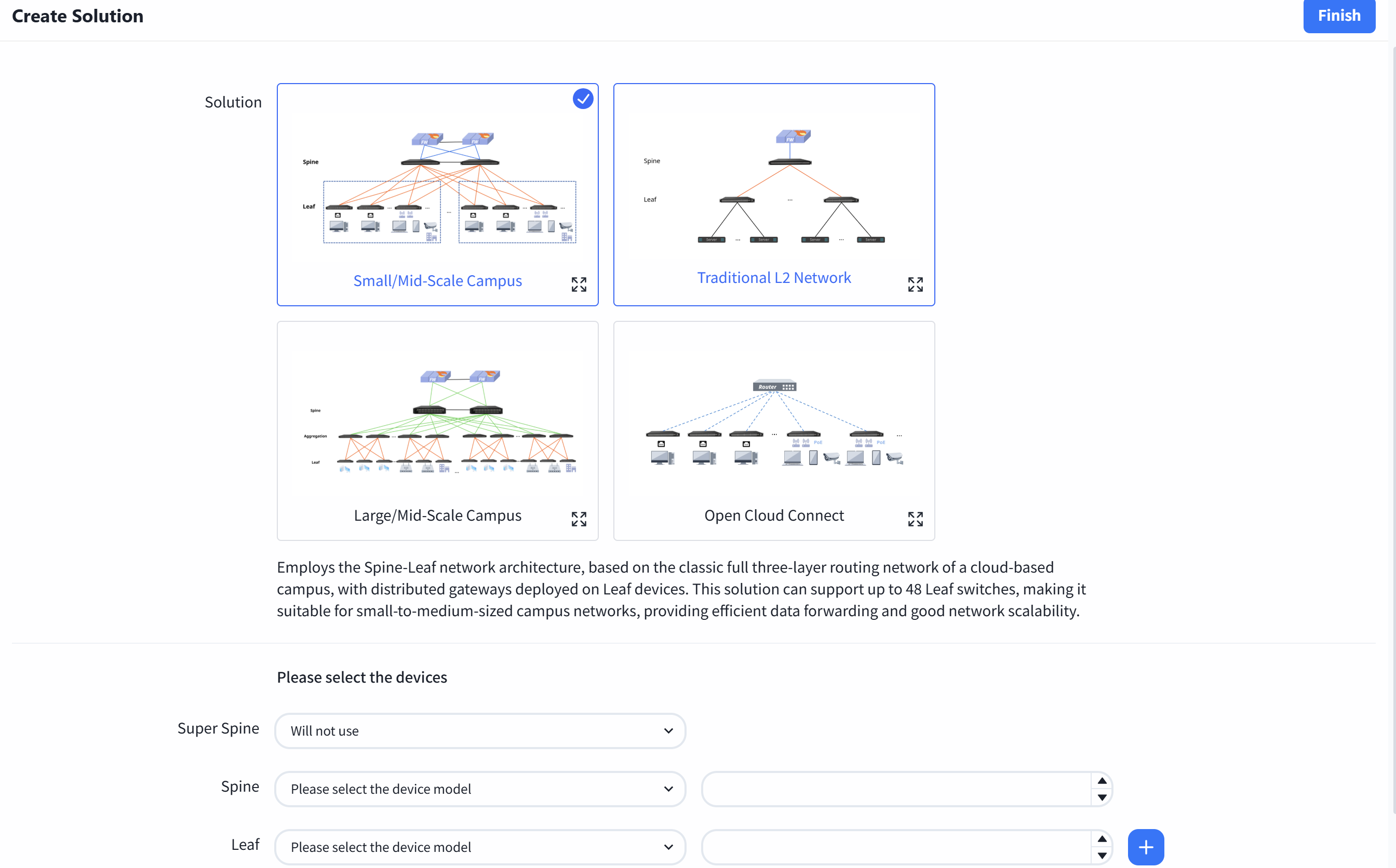
Small/Mid-Scale Campus
This is a full L3 network solution with a two-tier Spine-Leaf architecture, for example, using the CX308 series as the Spine devices and the CX204Y-48GT series as the Leaf devices: each Spine device can provide up to 48 interfaces to connect with Leaf devices, and each Leaf device offers 48 access interfaces. Thus, the network can support up to 48 x 48 = 2304 access interfaces. This scenario is suitable for smaller scale network.
Large/Mid-Scale Campus
This is a full L3 network solution with a three-tier Spine-Aggregation-Leaf architecture, for example, using the CX308 series as Spine devices, the CX206P-24S series as Aggregation devices, and the CX204Y-48GT series as Leaf devices: each Spine device can provide up to 48 interfaces to connect with Aggregation devices, each Aggregation device can provide up to 24 interfaces to connect with Leaf devices, and each Leaf device offers 48 access interfaces. Thus, the network can support up to 48 × 24 × 48 = 55,296 access interfaces. This scenario is suitable for larger scale network.
Traditional L2 Network
Traditional L2 network solution, Spine-Leaf L2 architecture, Leaf for pure L2 access, gateway deployed on Spine device.
Open Cloud Connect
The gateway is deployed on aggregation or access devices. Suitable for scenarios where there are already aggregation devices or access layer expansion in the park, providing two classic modes: layer 2 forwarding and access layer gateway.
Design Topology
Section titled “Design Topology”| Procedure | Description |
|---|---|
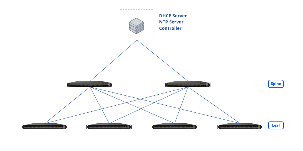
| Step 1 | Select the Small/Mid-Scale Campus network scenario, fill in the models and quantities of Spine and Leaf devices, then click [Save] to finish the pre-planning of the network topology. The controller will generate a recommended network topology based on the pre-planned typical network architecture.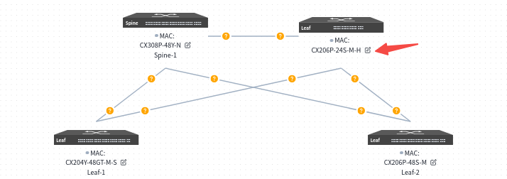 |
| Step 2 | Users can click the [Edit] button on the device side, select devices from the inventory to be applied to the current topology in the slide-out panel on the right, and then choose interconnection interfaces. |
MAC: Uniquely select a device via its MAC address. Loopback IP: Configure the IP address for the device’s Loopback0 interface, which will be used for in-band management of the device. Hostname: Configure the hostname of the device. Device role: Assign the device role as Spine or Leaf. ******Interconnection Interfaces:**Local Interface: The interface on the current device.Neighbor: Select the peer device connected to the local interface.Neighbor Port: The interface on the peer device interconnected with the current device’s local interface.
Or click [Import Configuration] in the upper right corner of the page to import the configuration.
Before importing, users can click [Export Configuration] on the right to obtain a blank configuration file.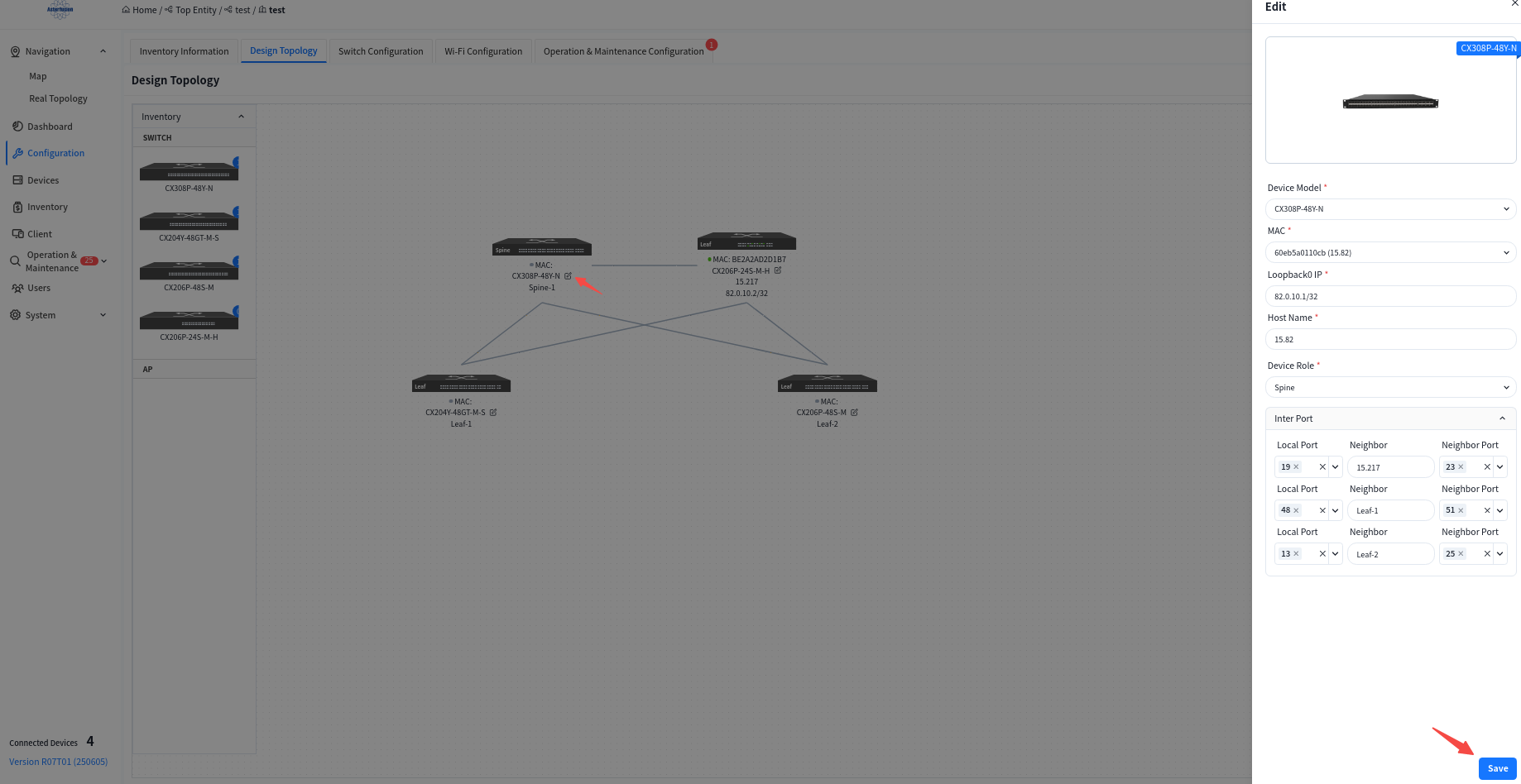

Basic Network
Section titled “Basic Network”| Procedure | Description |
|---|---|
| Step 1 | Click [basic network] to enter the Basic Network Configuration interface to configure the basic network that carries the service network, including the routing protocols between Leaf and Spine, and between Spine and up-link devices. Besides information such as IP addresses that must be specified by the user, the controller will dynamically generate basic configurations based on the network topology that do not require the user’s attention. |
| Step 2 | Configuring Spine device up-link interface information.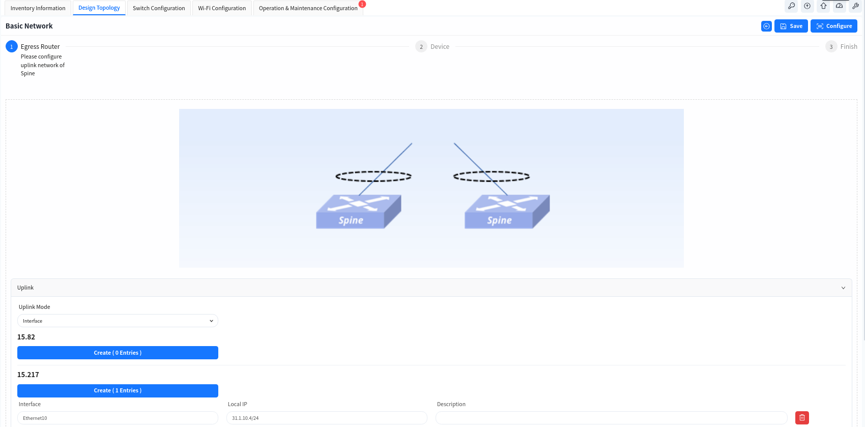 |
| Step 3 | Configure the IP address of the Spine device uplink interface and static routing information on the Spine device.Note If the Spine and the core device do not use static route but use dynamic route, user can click [Advance] button to configure it.[BGP Enable] Enable the BGP function of Spine device and configure the AS number and IP address information of the up-link device, so that Spine can establish BGP neighbor relationship with the up-link device.[OSPF Enable] Enable OSPF on Spine devices, configure the OSPF domain ID and establishment method, so that Spine and up-link devices can establish neighbor relationships via OSPF to synchronize routes.[Route Aggregation Enable] When the Spine devices enable the BGP function, the routing information of the terminal will be synchronized with the up-link device in form of aggregated routes.[HA] When enabled, the two Spine devices will provide a cross-device LAG interface to the up-link device through the MC-LAG function.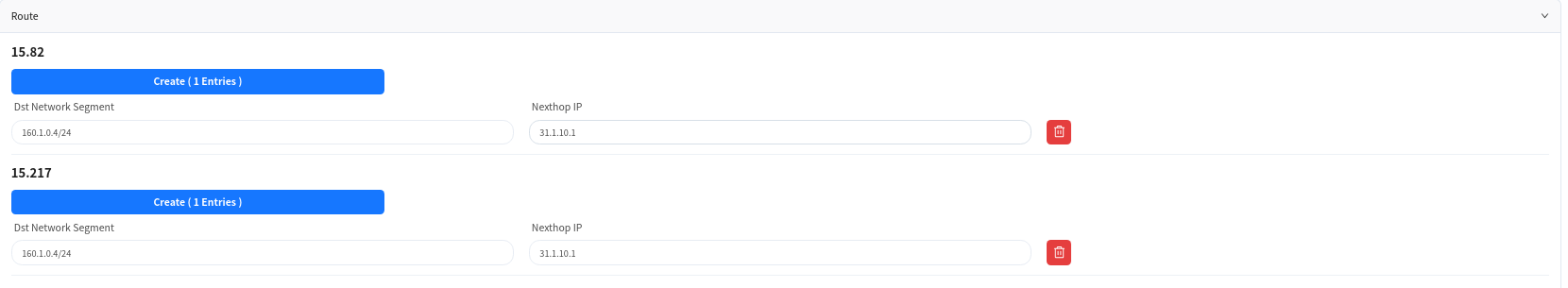 |
| Step 4 | Configure device management related information:** TimeZone**: Configure the system time zone.NTP: Configure NTP Server.SNMP: Configure SNMP community.Syslog: Configure syslog server IP address.TACACS+: Configure TACACS server IP address.Device ACL: Configure ACL rules restricting SSH, SNMP, TELNET connections to device. |
Wired Service Configuration
Section titled “Wired Service Configuration”Wired Service Configuration
Click [Switch Configure] to enter the wired service management interface, where you can configure corresponding service VLANs and IP gateways on switches for wired and wireless users, and specify the IP address of the DHCP server. Multiple service VLANs can be added to handle different service requirements.
| Procedure | |
|---|---|
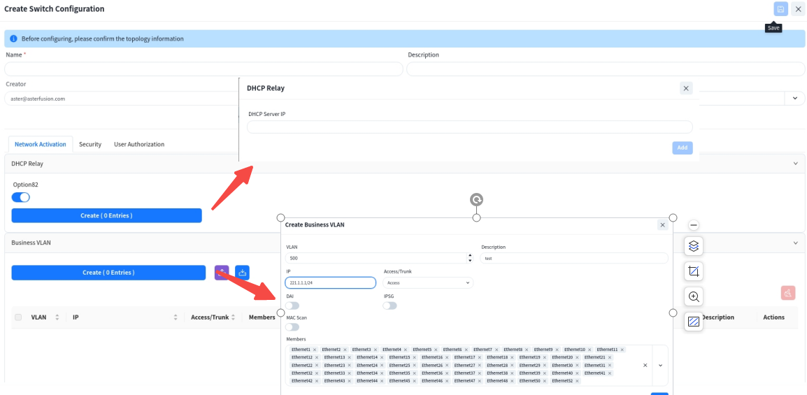
| Step 1 | [DHCP Relay] Configure the DHCP server IP address. When the DHCP server does not support recognizing the option82 field, the option82 option needs to be disabled. |
| Step 2 | **[Business VLAN]**VLAN: Create service VLANs. Note that in addition to basic service VLANs, a management VLAN for user APs to connect to the controller must also be created.IP: Configure an address as the gateway for the service VLAN.Access/Trunk: Select the mode according to whether the interface transmits/receives packets with VLAN tags.Access: Accepts packets without VLAN tag, typically configured for the AP management VLAN.Trunk: Accepts packets with VLAN tag, typically configured for service VLANs.Member Interfaces: Click the drop-down arrow to select the member interfaces of the VLAN.DAI/IPSG: The controller enables the DHCP Snooping function by default to effectively prevent DHCP Server impersonation attacks, ensuring DHCP clients obtain IP addresses from legitimate DHCP servers. Administrators do not need to manage trusted/untrusted interfaces on different devices-the controller automatically generates configurations based on topology information. |
| Administrators can enable ARP inspection (DAI) and IP source guard (IPSG) based on network security requirements. These functions validate host legitimacy using global DHCP Snooping entries to prevent malicious hosts from forging legitimate identities or attacking the network via self-assigned IP addresses, thus avoiding potential IP conflicts.MAC Scan (optional): In Ethernet, MAC address table entries guide devices to perform layer 2 data forwarding. After enabling this function, ARP Request packets corresponding to the IP address in the request table can be sent based on the Snooping and User bind table entries, which are commonly used for dumb terminals and server deployment. Proactively update device MAC and ARP table entries. | |
| Step 3**(Optional)** | [Security] Administrators can further enhance network security by configuring device management ACLs and service ACLs to set blacklists/whitelists for user internet traffic.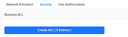 |
| Step 4**(Optional)** | [User Authorization] In enterprise networks or public places with high security requirements, enable 802.1x-based user authentication. This ensures only authenticated users and devices can access network resources, enhancing security. Through the graphical interface, administrators can define and apply authentication policies, including specifying ports for 802.1x authentication and setting different authentication rules.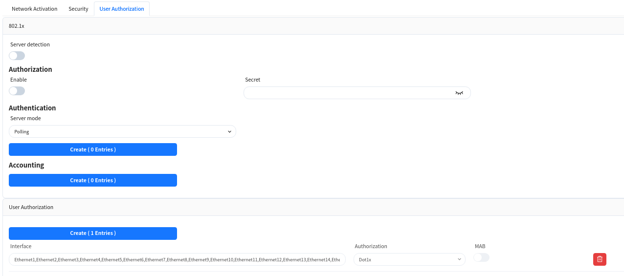 |
DHCP Server Configuration
The controller supports users to configure DHCP Server functionality on Spine devices.
| Procedure | Description |
|---|---|
| Step 1 | click on [Configuration]-[Wired Service Configuration]-[DHCP] to enter the DHCP Server configuration interface, and click on the [+] button on the page to create a new configuration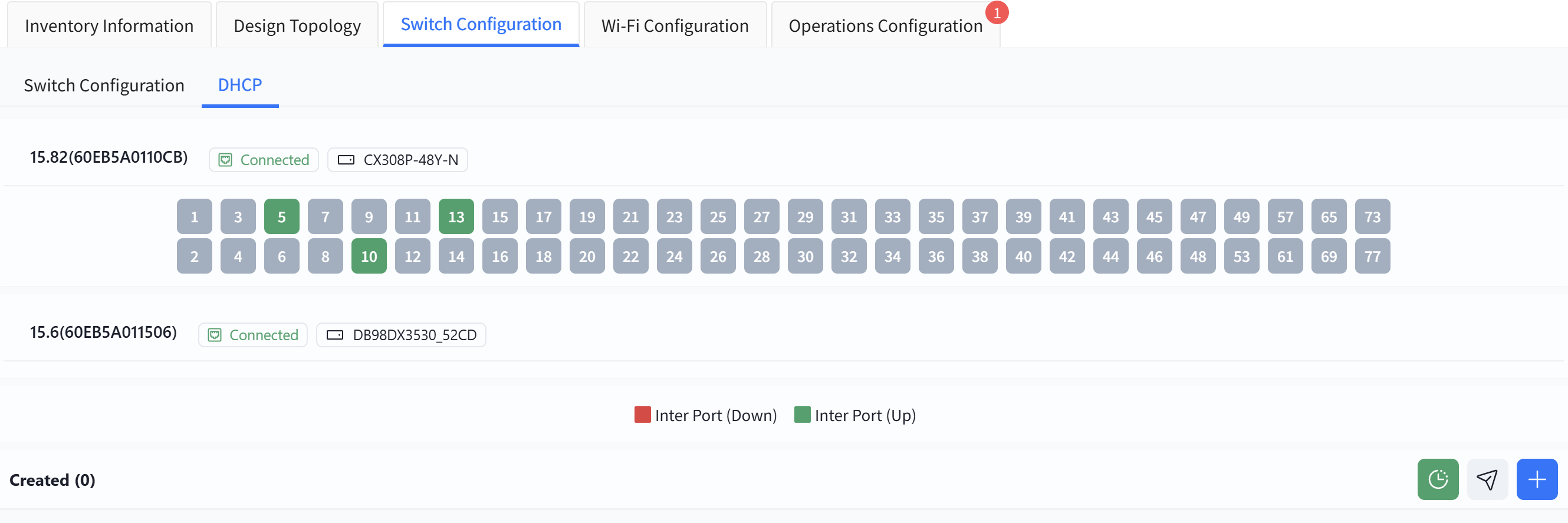 |
| Step 2 | Follow the prompts on the page to configure address pool details. Fields marked with * are mandatory. |
Name: User defined.
Network: Specify the network segment where the IP address assigned by the DHCP server to the DHCP client is located.
Gateway Address: Specify the gateway address assigned by the DHCP server to the DHCP client.
DNS: Specify the DNS server address.
Address Pool: Specify the address range allocated by the DHCP server to DHCP clients.
Lease Time: Specify the IP address lease time.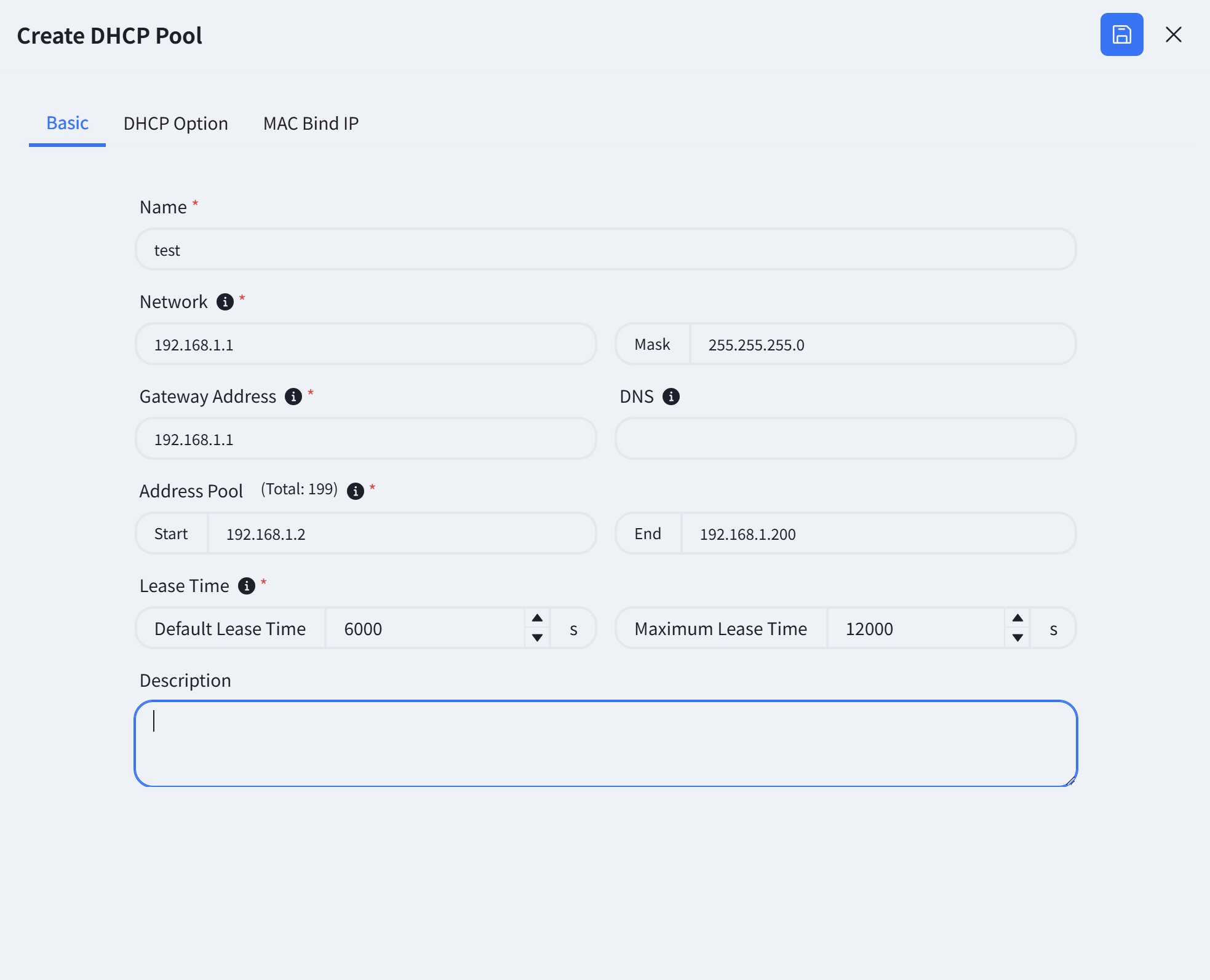 |
| Step 3
(Optional) | Click on [DHCP Option] and fill in the relevant information.
Next Server: Configure the IP address of the network server to be used in the next step during the DHCP client startup process.
Vendor Specific (Option 43): Hexadecimal number used to transmit vendor specific information to client devices of a particular vendor.
Server Identifier (Option 54): Notify the client of the address of the DHCP server.
TFTP Server (Option 66): Configure the TFTP server address used by DHCP clients.
Bootfile Name (Option 67): Configure the startup configuration file name for DHCP clients.
CAPWAP AC (Option 138): DHCP options specifically designed for wireless AP discovery controllers, fill in the controller IP address.
|
| Step 3
(Optional) | Click on [DHCP Option] and fill in the relevant information.
Next Server: Configure the IP address of the network server to be used in the next step during the DHCP client startup process.
Vendor Specific (Option 43): Hexadecimal number used to transmit vendor specific information to client devices of a particular vendor.
Server Identifier (Option 54): Notify the client of the address of the DHCP server.
TFTP Server (Option 66): Configure the TFTP server address used by DHCP clients.
Bootfile Name (Option 67): Configure the startup configuration file name for DHCP clients.
CAPWAP AC (Option 138): DHCP options specifically designed for wireless AP discovery controllers, fill in the controller IP address.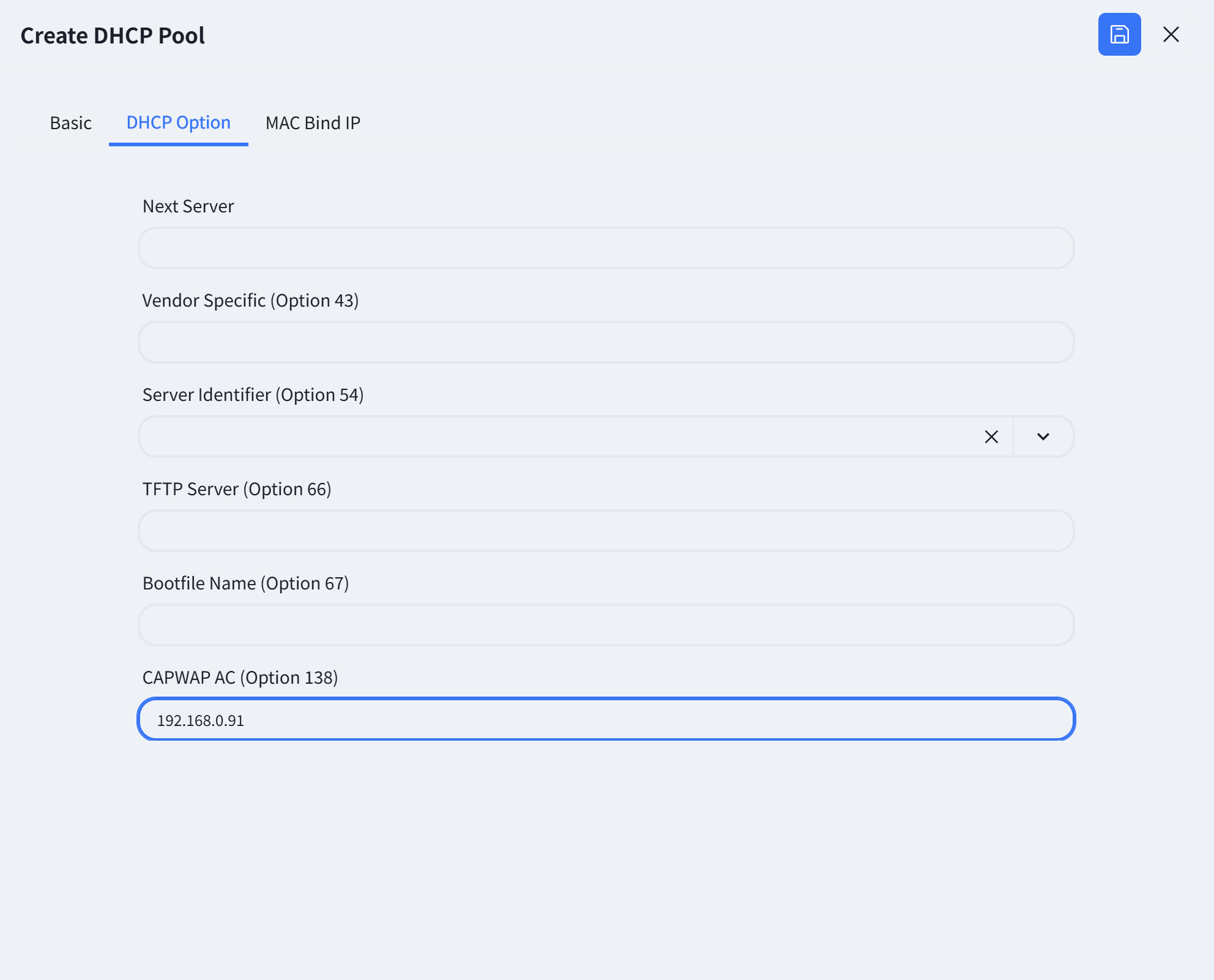 |
| Step 4 (Optional) | The controller supports configuring MAC binding IP function, which users can fill in as needed.
|
| Step 4 (Optional) | The controller supports configuring MAC binding IP function, which users can fill in as needed.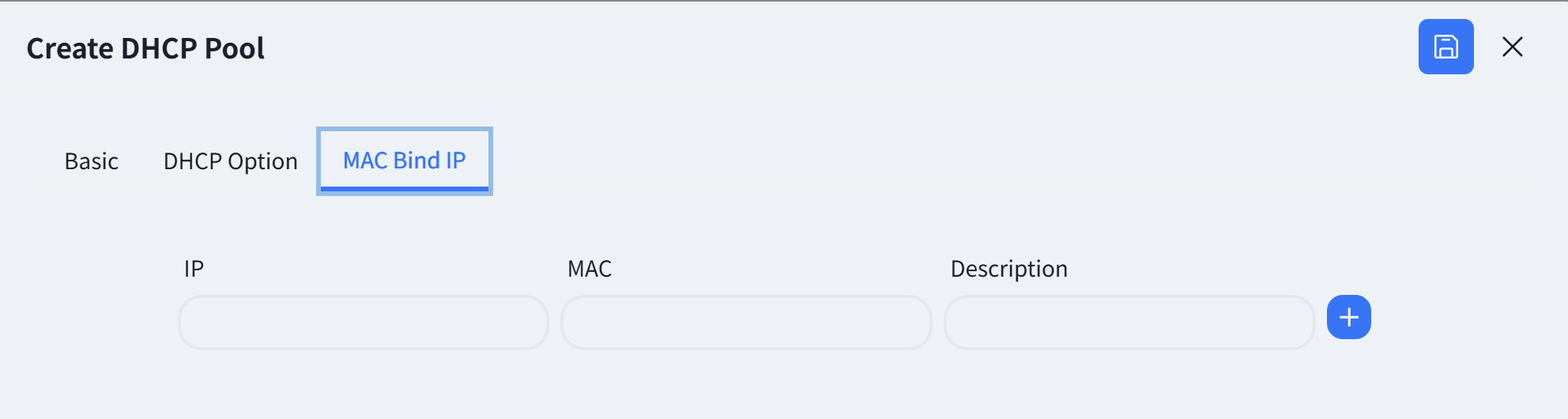 |
| Step 5 | Click save. |
| Step 6 | Click the [Push Configuration] button, select the configuration edited in the previous step, click [Next] — [Start], and send the configuration to the Spine switch.
|
| Step 5 | Click save. |
| Step 6 | Click the [Push Configuration] button, select the configuration edited in the previous step, click [Next] — [Start], and send the configuration to the Spine switch.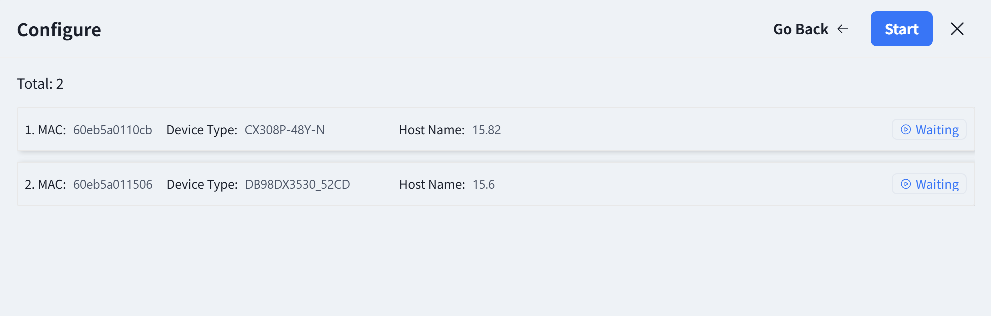 |
|
Wireless Service Configuration
Section titled “Wireless Service Configuration”| Procedure | Description |
|---|---|
| Step 1 | Click [Wireless Configuration] - [+] - [Create Configuration] to configure the necessary basic information for the wireless AP, e.g. SSID settings, security policy. The controller can automatically generate the corresponding configuration script based on the administrator’s input. |
The controller supports the configuration of different wireless service configurations, and after the AP goes online, it will determine which configuration should be issued to the AP based on the [CONFIG TAG] attributes of the configuration.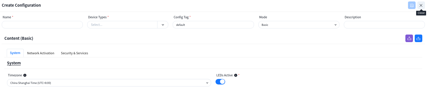 | |
| Step 2 | Set time zone and select whether to enable LED.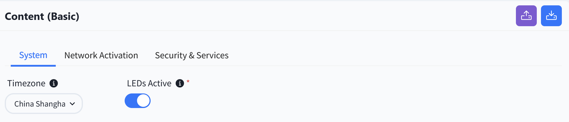 |
| Step 3 | Configure SSID related content |
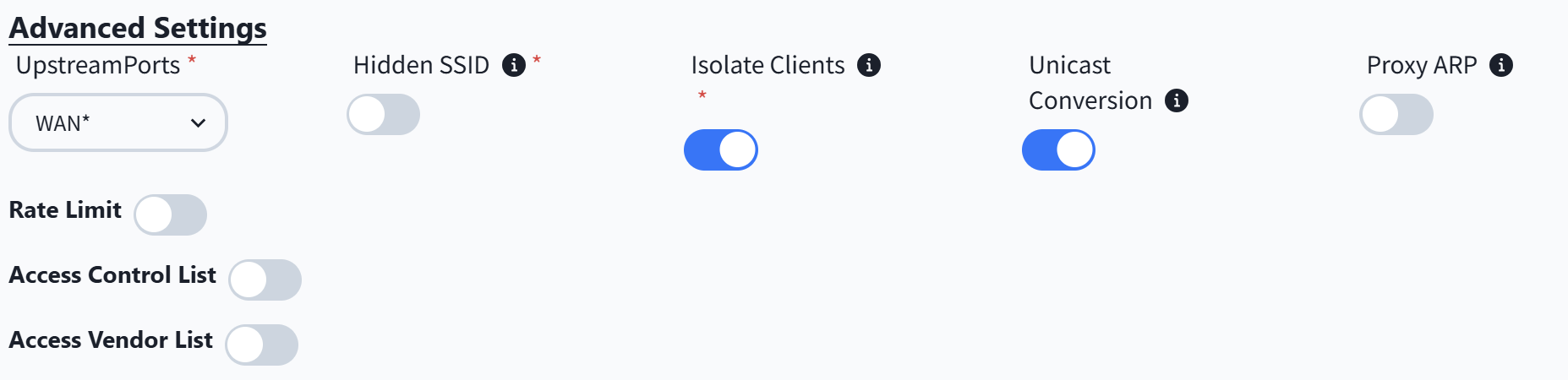
If there is a specific application scenario, the administrator can also customize the default configuration of the AP in the [advanced settings].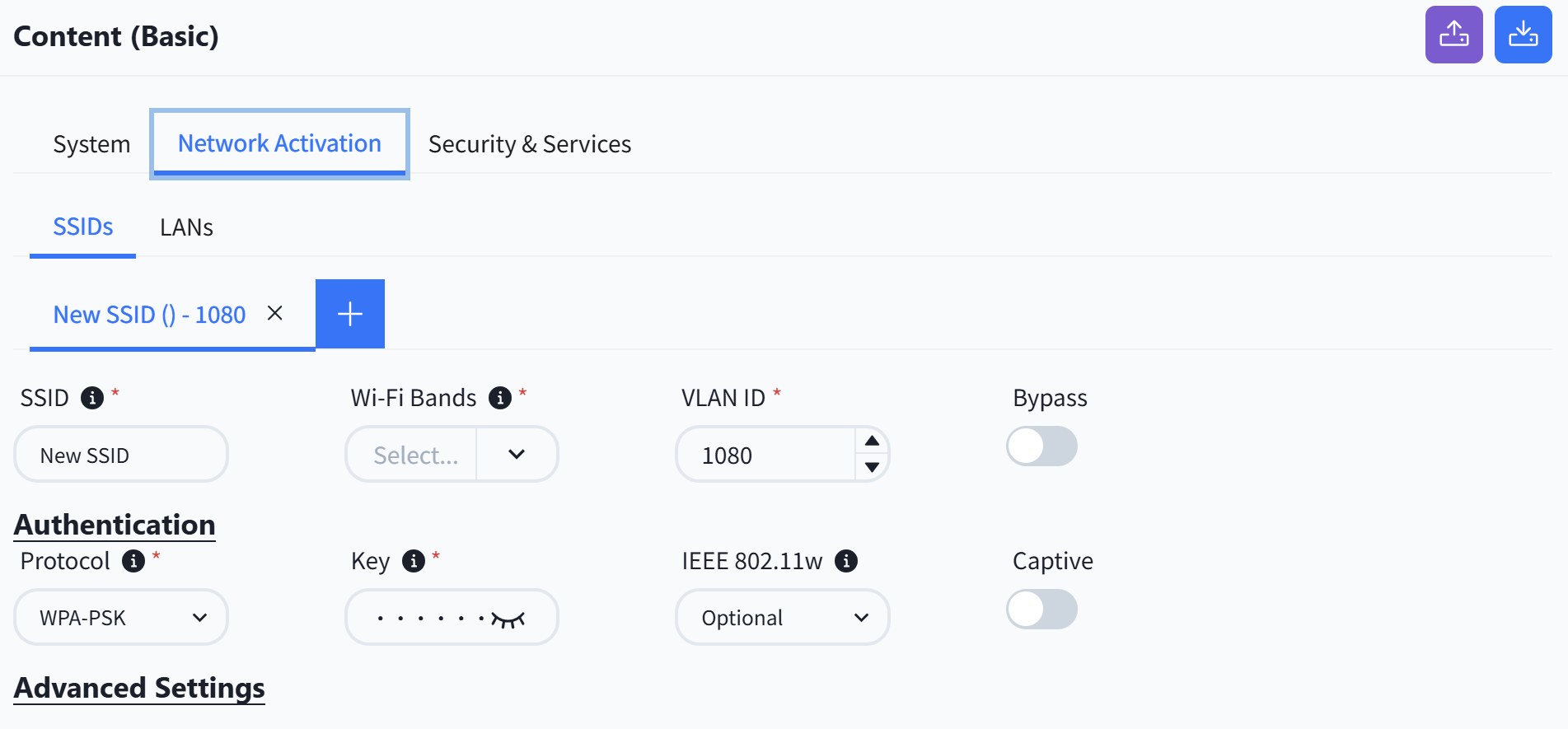
 |
| Step 4 | Configure LAN interface.
When the AP is one that has an extended wired interface and is capable of accessing terminals by wired means, such as a panel AP, the user can configure the access method for wired terminals through the configuration in LANs.
UpstreamPorts: Specify the up-link interfaces for wired terminal to access the network through AP, usually it is the interface for AP to connect to the switch, and keep the same with [UpstreamPorts] in [SSID] — [Advanced] Settings, the default is: WAN*.
DownstreamPorts: Interfaces for wired terminal access.
Downstream VLAN Tag: Whether the wired terminal carries VLAN Tag.
VLAN ID: The AP receives messages from wired terminals that add this VLAN TAG to identify.
DHCP Snooping Trusted: DHCP Snooping Trusted interface, if the wired terminal needs to obtain IP address through DHCP service, this switch needs to be on.
|
| Step 4 | Configure LAN interface.
When the AP is one that has an extended wired interface and is capable of accessing terminals by wired means, such as a panel AP, the user can configure the access method for wired terminals through the configuration in LANs.
UpstreamPorts: Specify the up-link interfaces for wired terminal to access the network through AP, usually it is the interface for AP to connect to the switch, and keep the same with [UpstreamPorts] in [SSID] — [Advanced] Settings, the default is: WAN*.
DownstreamPorts: Interfaces for wired terminal access.
Downstream VLAN Tag: Whether the wired terminal carries VLAN Tag.
VLAN ID: The AP receives messages from wired terminals that add this VLAN TAG to identify.
DHCP Snooping Trusted: DHCP Snooping Trusted interface, if the wired terminal needs to obtain IP address through DHCP service, this switch needs to be on.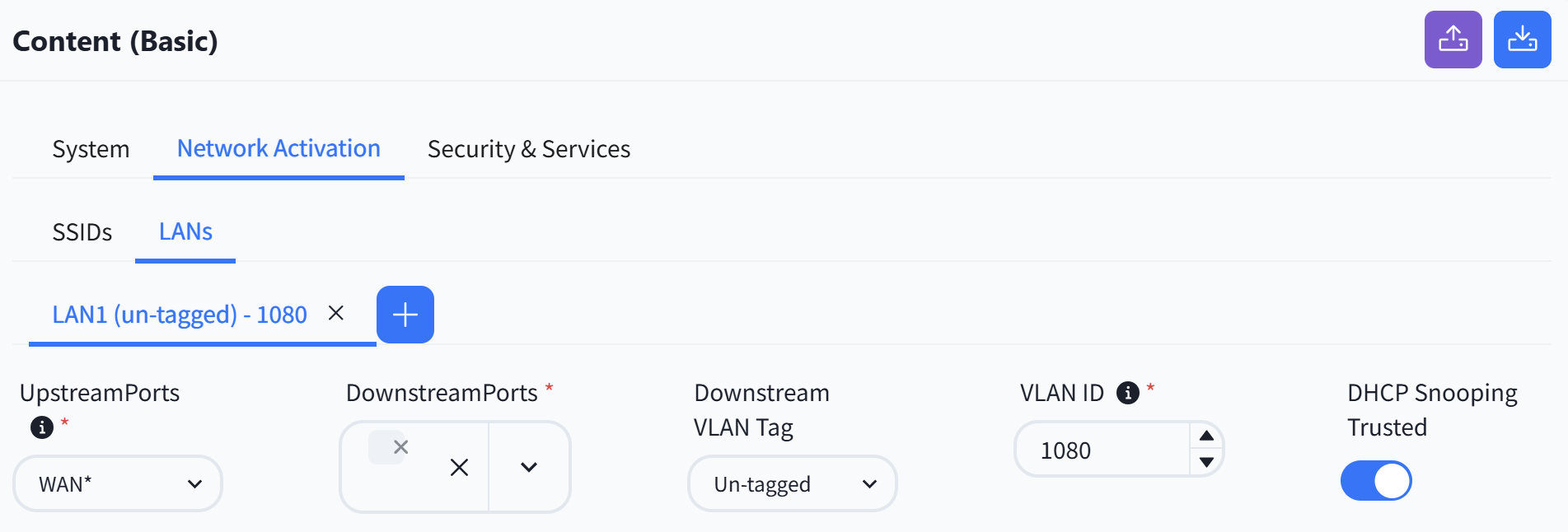 |
|
Wireless RF Configure
When the AP is online and connected to the controller, according to the actual deployment environment, if you need to adjust the wireless RF related configuration of the AP, you can configure it in the [Radio Configuration] page.

Configuration Release
Section titled “Configuration Release”Switch
| Procedure | Description |
|---|---|
| Step 1 | The equipment is managed by the controller. |
| Devices in the factory state, both management and service ports, with a status of Up will initiate a DHCP request to ask the DHCP server to provide a temporary management IP address and the controller IP address on the cloud to connect to the controller for configuration information. | |
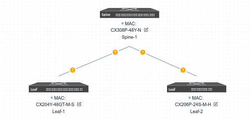
| Step 2 | After all devices have finished going online, click [Real topology] to confirm that the topology recognized by the controller based on the online devices is consistent with the design topology. After confirming that there is no error, follow the steps below to issue the configuration: |
| Step 3 | Confirm whether the actual topology matches the plan.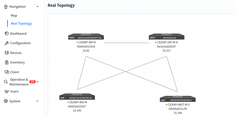 |
| Step 4 | Click [Configuration] - [Design Topology] - [Basic Network] - [Push Configuration] to issue the basic configuration for all devices. |
By default, the controller will select all switches. Click the [Next] - [Start] button to start issuing basic network configurations for the switches.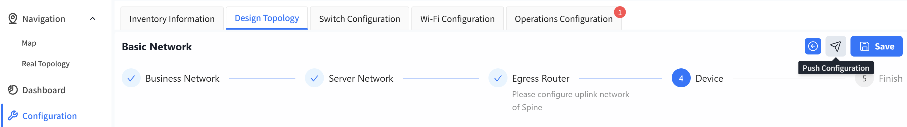 | |
| Step 5 | Click [Configuration] - [Switch Configuration] - [Push Configuration] to issue a configuration for the device.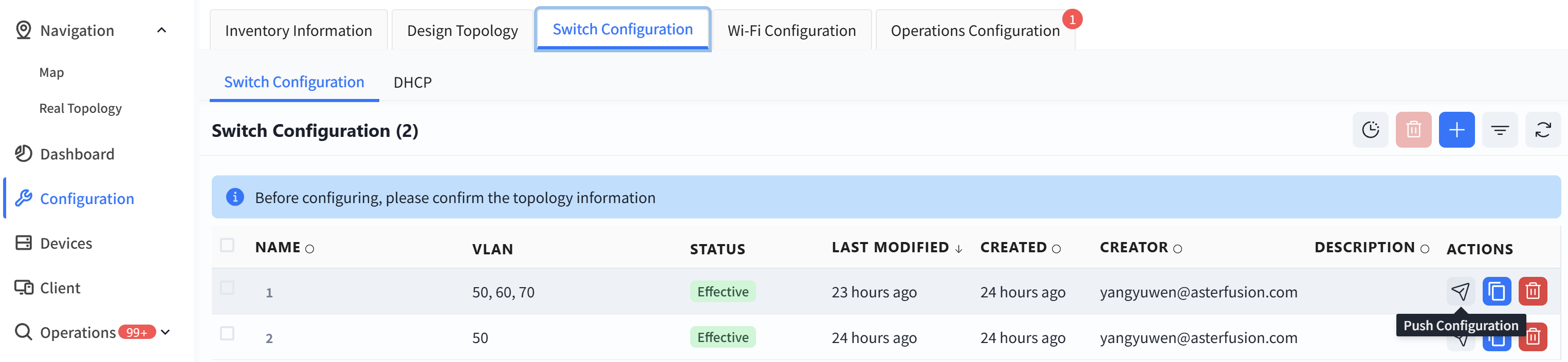 |
AP
The AP does not need to manually issue the configuration. After the configuration of the device is issued and takes effect, the PoE power supply function of the switch is turned on, and the AP can power on and work. When the AP connects to the controller with the information obtained through the DHCP service, the controller will automatically send the configuration to the corresponding AP based on the comparison between the TAG identification stored in the AP inventory and the TAG identification in the planning configuration.
Large/Mid-scale Network Deployment
Section titled “Large/Mid-scale Network Deployment”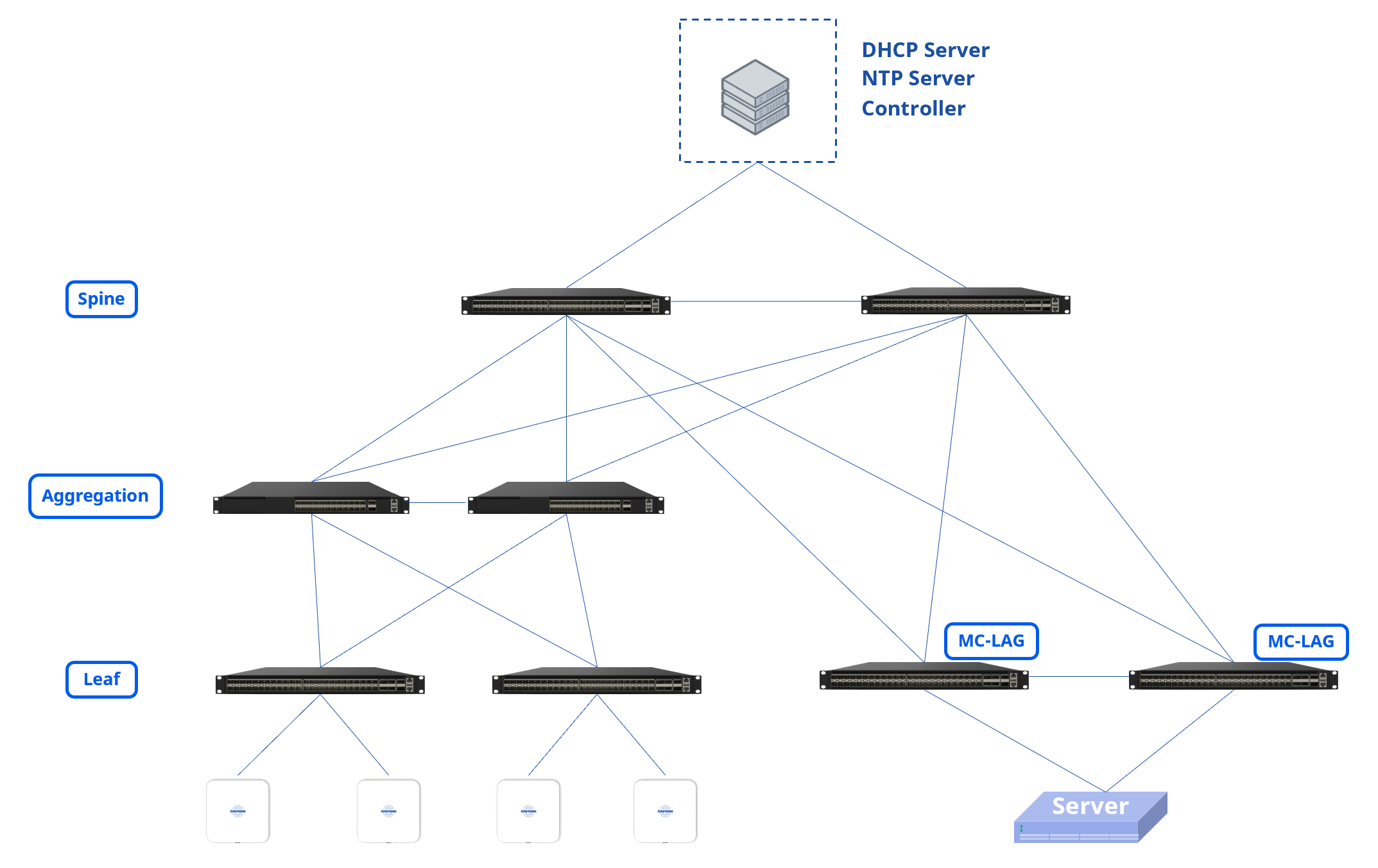
The Large/Mid-Scale Campus network can adopt a Spine-Aggregation-Leaf three-level structure, which expands the number of accessible Leaf devices through Aggregation and further expands the number of access ports. Support configuring MC-LAG access servers on Leaf switches.
Design Topology
Section titled “Design Topology”| Procedure | Description |
|---|---|
| Step 1 | The device selection and topology editing are the same as the Small/Mid-scale campus networks. If MC-LAG needs to be deployed, it is necessary to choose the model and quantity of server network switch group and switches during topology planning, and MC-LAG Enable should be automatically enabled on the server area leaf switch after selection.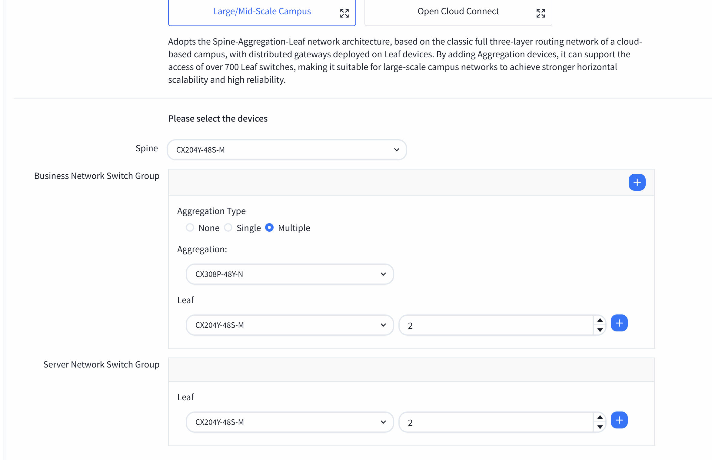 |
| Step 2 | The topology overview is shown below: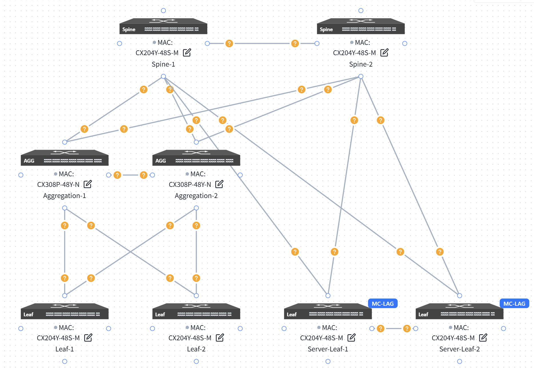 |
| Step 3 | Click on the topology editor in the bottom right corner of the device, and enable MC-LAG Enable on the leaf switch.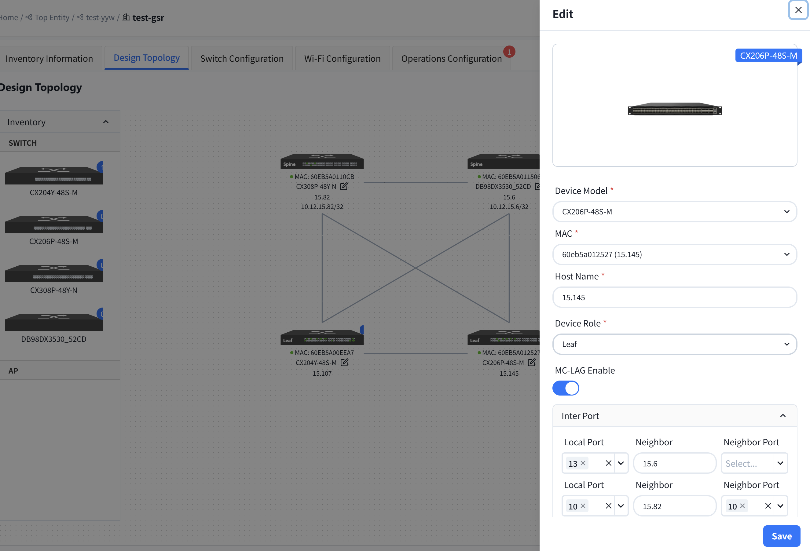 |
Basic Network
Section titled “Basic Network”| Procedure | Description |
|---|---|
| Step 1 | Configure the in-band management network for aggregation devices. Typically. the Spine and Leaf devices are Layer 3 devices. in-band management can use the Loopback0 address. while the aggregation device is a Layer 2 device for which you need to configure the management VLAN and IP. |
Controller can assign an in-band management address to each aggregation device based on the address segments that are entered by the user.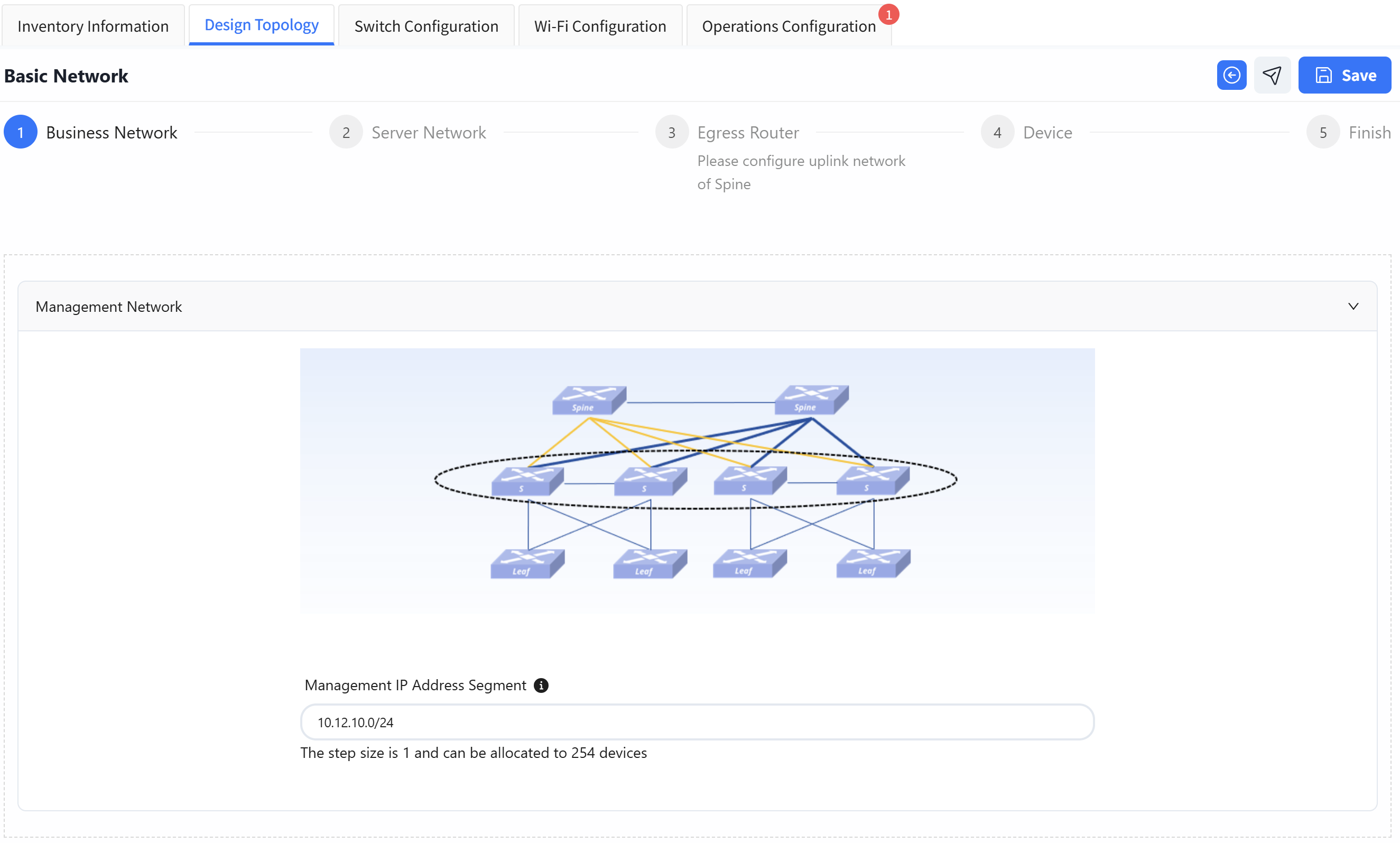 | |
| Step 2 | Configure in band management network for Leaf devices. (Optional. If out of band management is selected, there is no need to configure the management address range). |
Configure the Peerlink interface VLAN and Peerlink IP.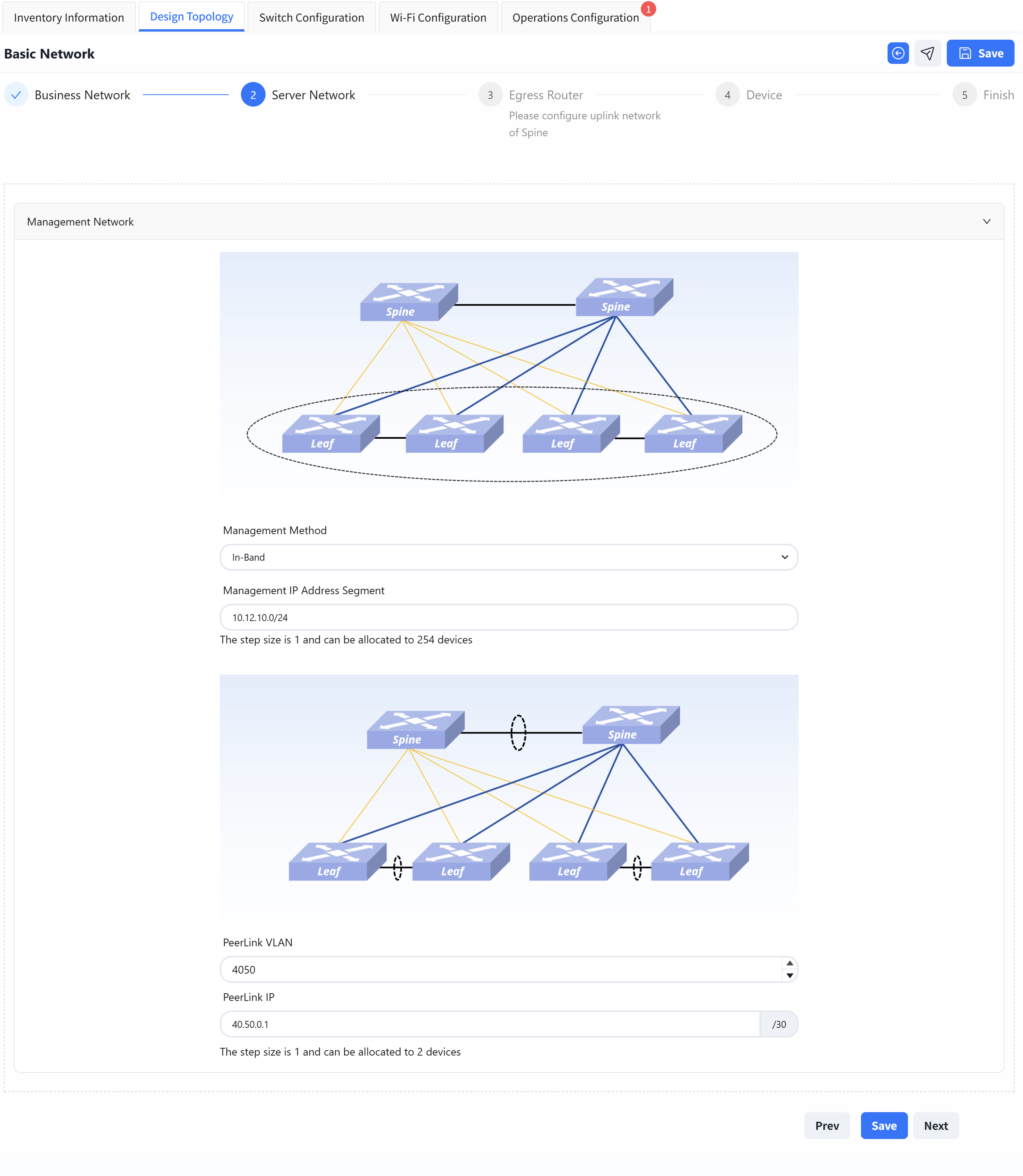 | |
| Step 3 | The configuration of Egress route part is consistent with the [Small/Mid-Scale Network Deployment], please refer to the previous section to complete the configuration. |
| Step 4 | The configuration of Device Management part is consistent with the [Small/Mid-Scale Network Deployment], please refer to the previous section to complete the configuration. |
Wired Service Configuration
Section titled “Wired Service Configuration”Business Network Switch Group Wired Service Configuration
Default configuration type selection, the rest is the same as [Small/Mid-Scale Network Deployment], please refer to the previous section to complete the configuration.
Server Network Switch Group Wired Service Configuration
| Procedure | Description |
|---|---|
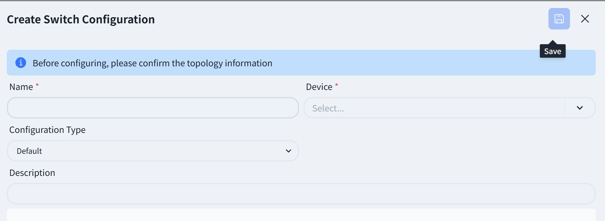
| Step 1 | Create Leaf Switch Configuration |
| Select [Configuration Type] as server area. | |
| Select [Device] as the leaf MC-LAG pair that needs to be configured. | |
Select [Device Role] as leaf.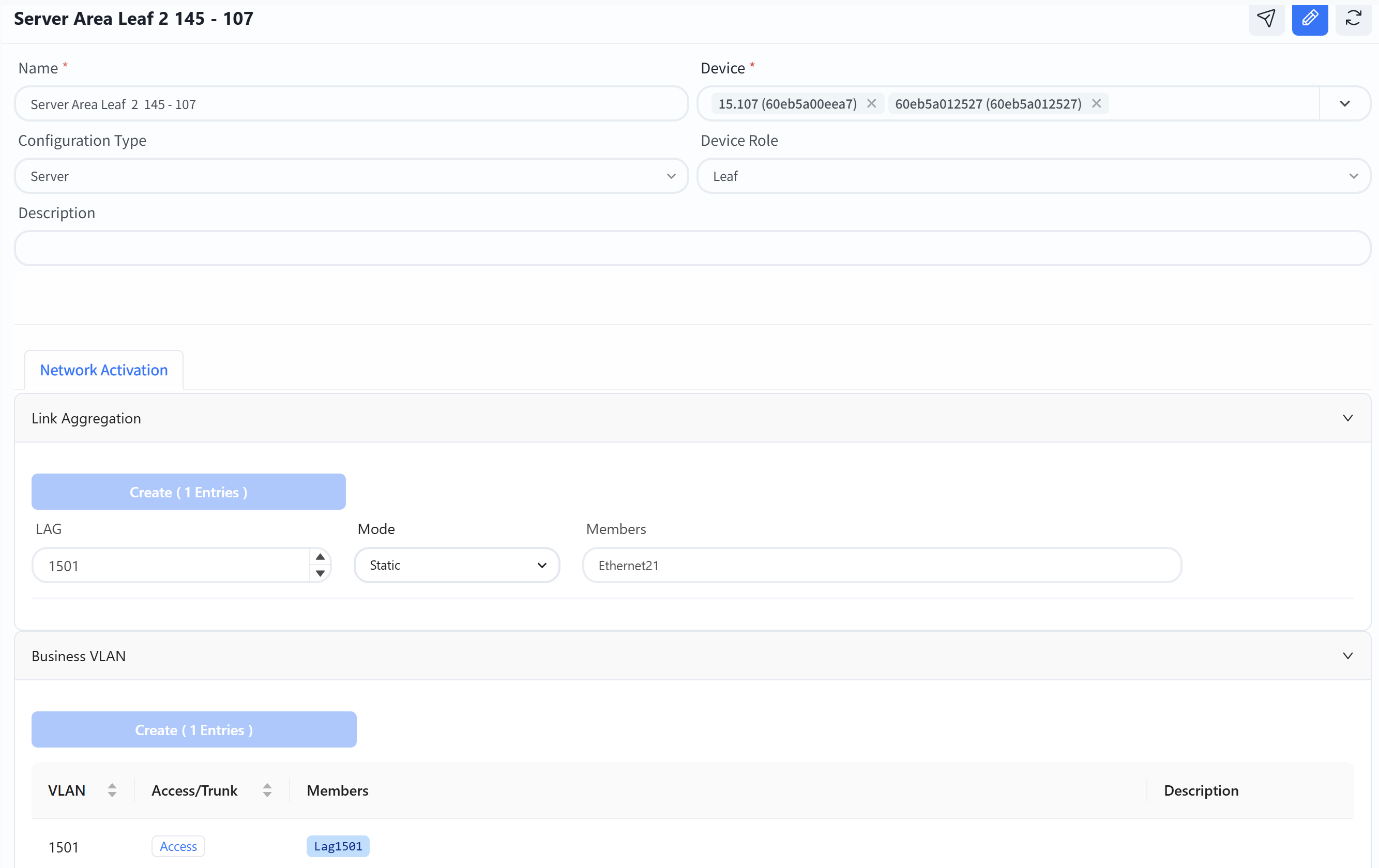 | |
| Step 2 | The Leaf switch of MC-LAG network needs to be configured with link aggregation port and business VLAN. |
LAG: Link Aggregation ID, users can create IDs within the range of 1501-2000 as needed.
Mode: Static/LACP, choose whether the link aggregation mode is static or LACP dynamic negotiation.
Member: Select the member interface connected to this business server.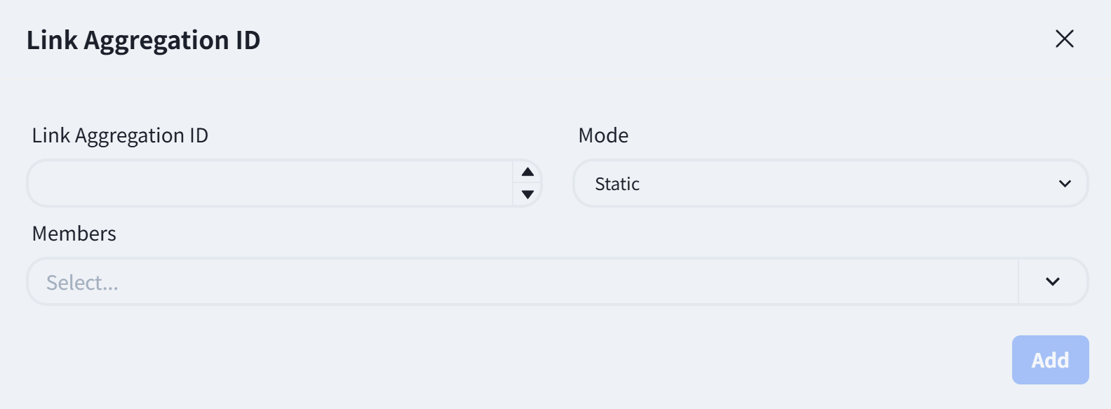 |
| Step 3 | Create business VLAN for Leaf switch
|
| Step 3 | Create business VLAN for Leaf switch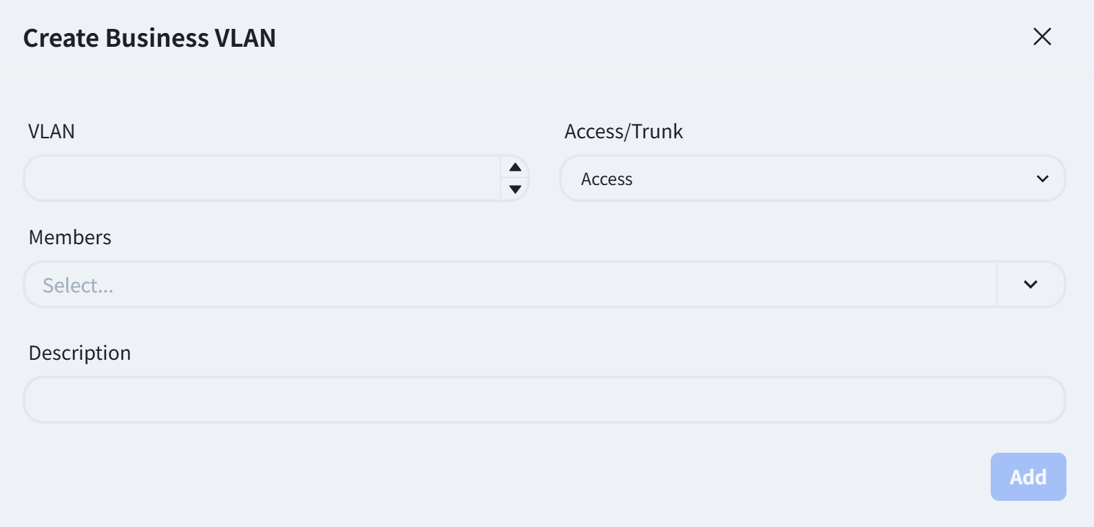 |
| Step 4 | Create Spine switch configuration
The business gateway of MC-LAG network is deployed on Spine devices, and when selecting devices, devices of Spine type also need to be added. Create a business gateway for the business VLAN corresponding to the Leaf switch in the server area.
|
| Step 4 | Create Spine switch configuration
The business gateway of MC-LAG network is deployed on Spine devices, and when selecting devices, devices of Spine type also need to be added. Create a business gateway for the business VLAN corresponding to the Leaf switch in the server area.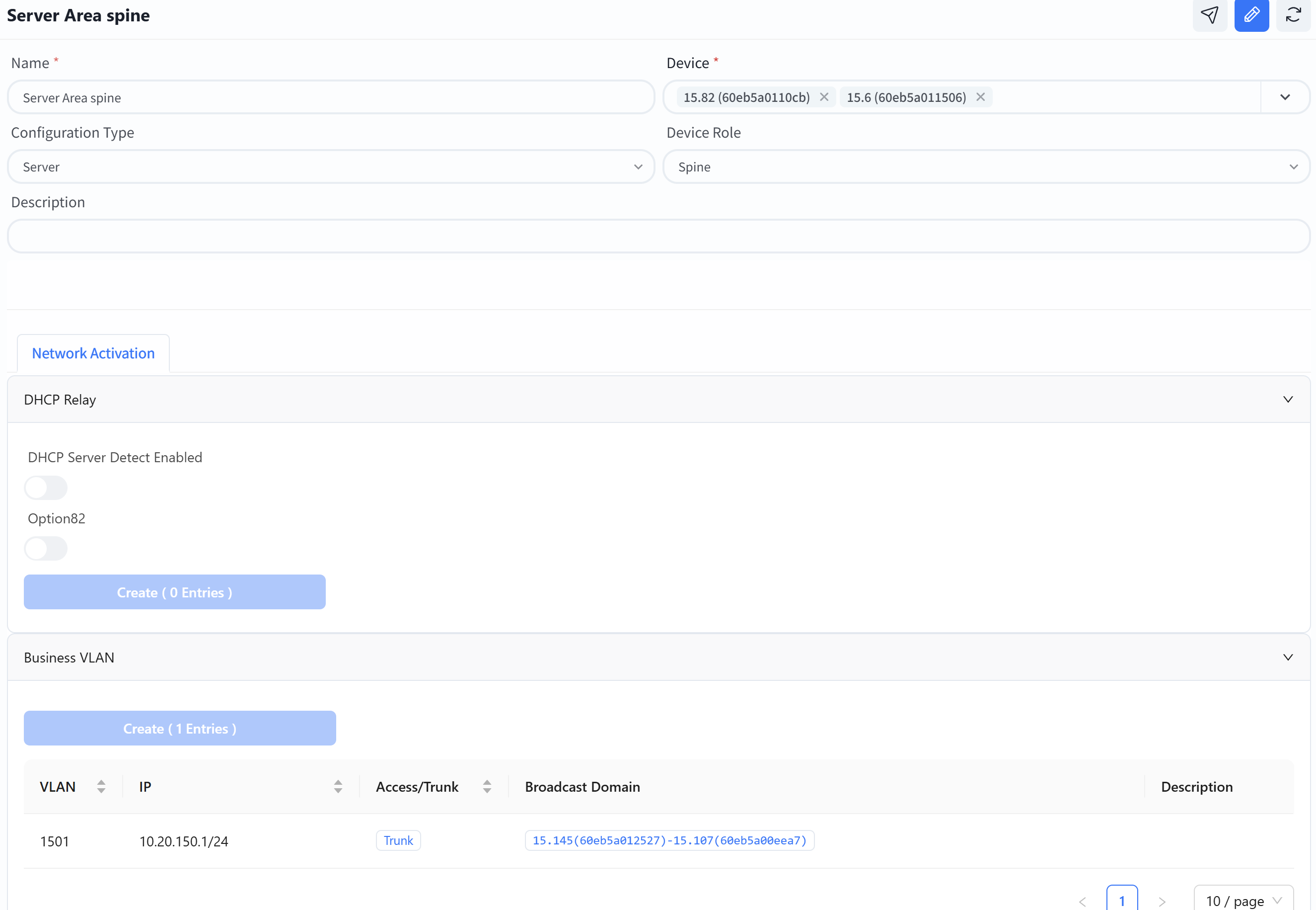 |
| Step 5
(Optional) | Configure the IP address of the DHCP server. If the terminal server needs to obtain an IP address from the DHCP server, the DHCP relay needs to be configured.
If the DHCP server does not support recognizing the option82 field, the option82 option needs to be turned off. |
| Step 6 | Configure the business VLAN for Spine switch
|
| Step 5
(Optional) | Configure the IP address of the DHCP server. If the terminal server needs to obtain an IP address from the DHCP server, the DHCP relay needs to be configured.
If the DHCP server does not support recognizing the option82 field, the option82 option needs to be turned off. |
| Step 6 | Configure the business VLAN for Spine switch
Broadcast domain: Select the MAC address of the leaf switch corresponding to the VLAN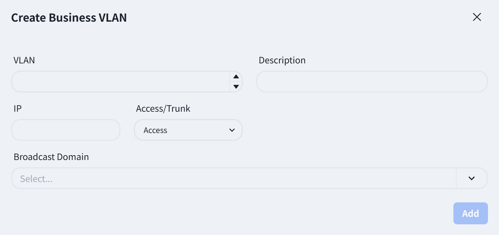 |
| Step 7
(Optional) | DHCP Server configuration please refer to the previous chapters, Spine will automatically run DHCP failover to ensure business stability. |
|
| Step 7
(Optional) | DHCP Server configuration please refer to the previous chapters, Spine will automatically run DHCP failover to ensure business stability. |
Wireless Service Configuration
Section titled “Wireless Service Configuration”The configuration of this part is consistent with the Egress route of [Small/Mid-Scale Network Deployment], please refer to the previous section to complete the configuration.
Configuration Release
Section titled “Configuration Release”The configuration of this part is consistent with the Egress route of [Small/Mid-Scale Network Deployment], please refer to the previous section to complete the configuration.
Traditional L2 Network Deployment
Section titled “Traditional L2 Network Deployment”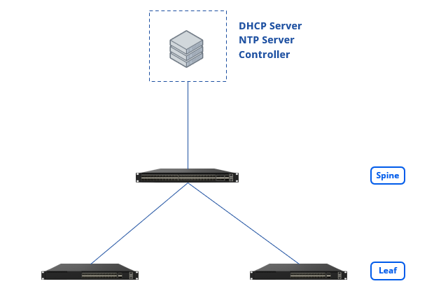
Design Topology
Section titled “Design Topology”Device selection and topology editing is the same as for the Small/Mid-Scale Campus network. The topology is summarized as shown below:
Basic Network
Section titled “Basic Network”| Procedure | Description |
|---|---|
| Step 1 | specify a VLAN ID as the in-band management VLAN, configure the address segment of the management IP and the gateway address for in-band management (this gateway address will be configured on the Spine device), and select the member interfaces of the VLAN and the mode (trunk/access) when joining the VLAN.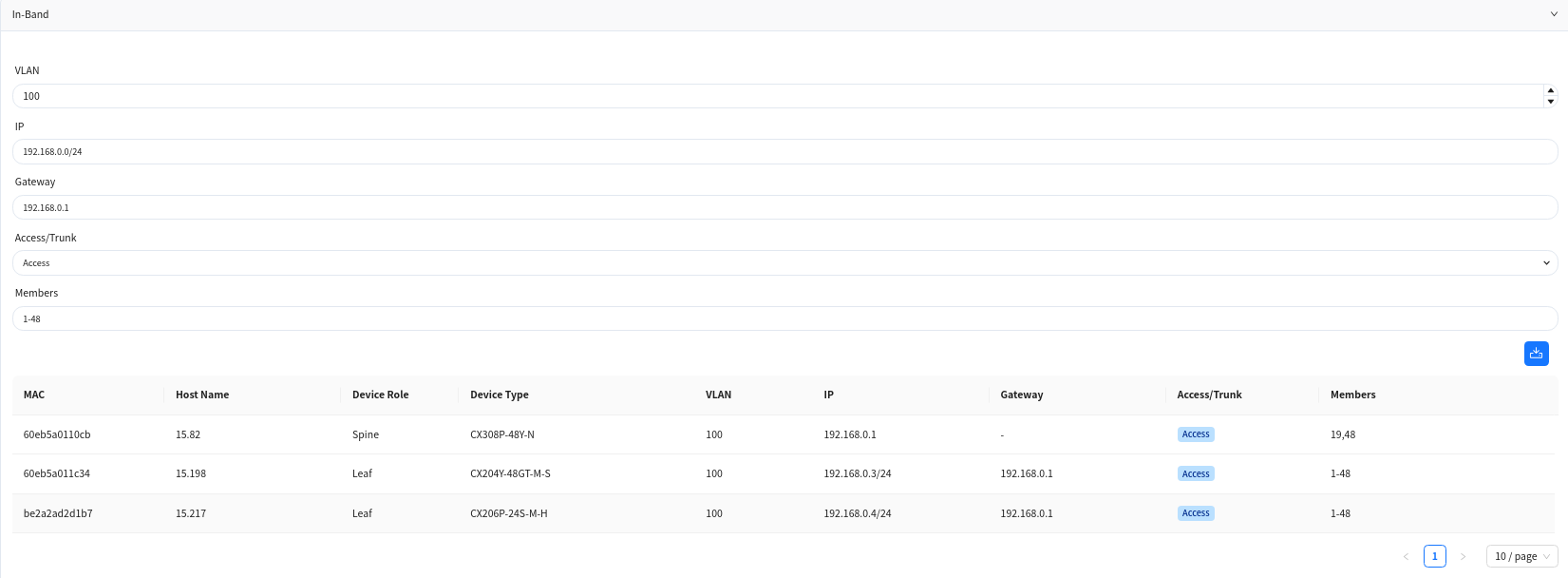 |
| Step 2 | Select the interface ID of the Spine device’s up-link interface and configure the IP address.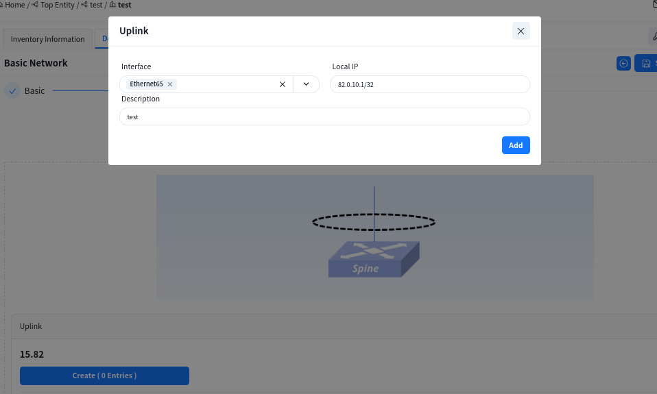 |
| Step 3 | Configure default route for Spine switch.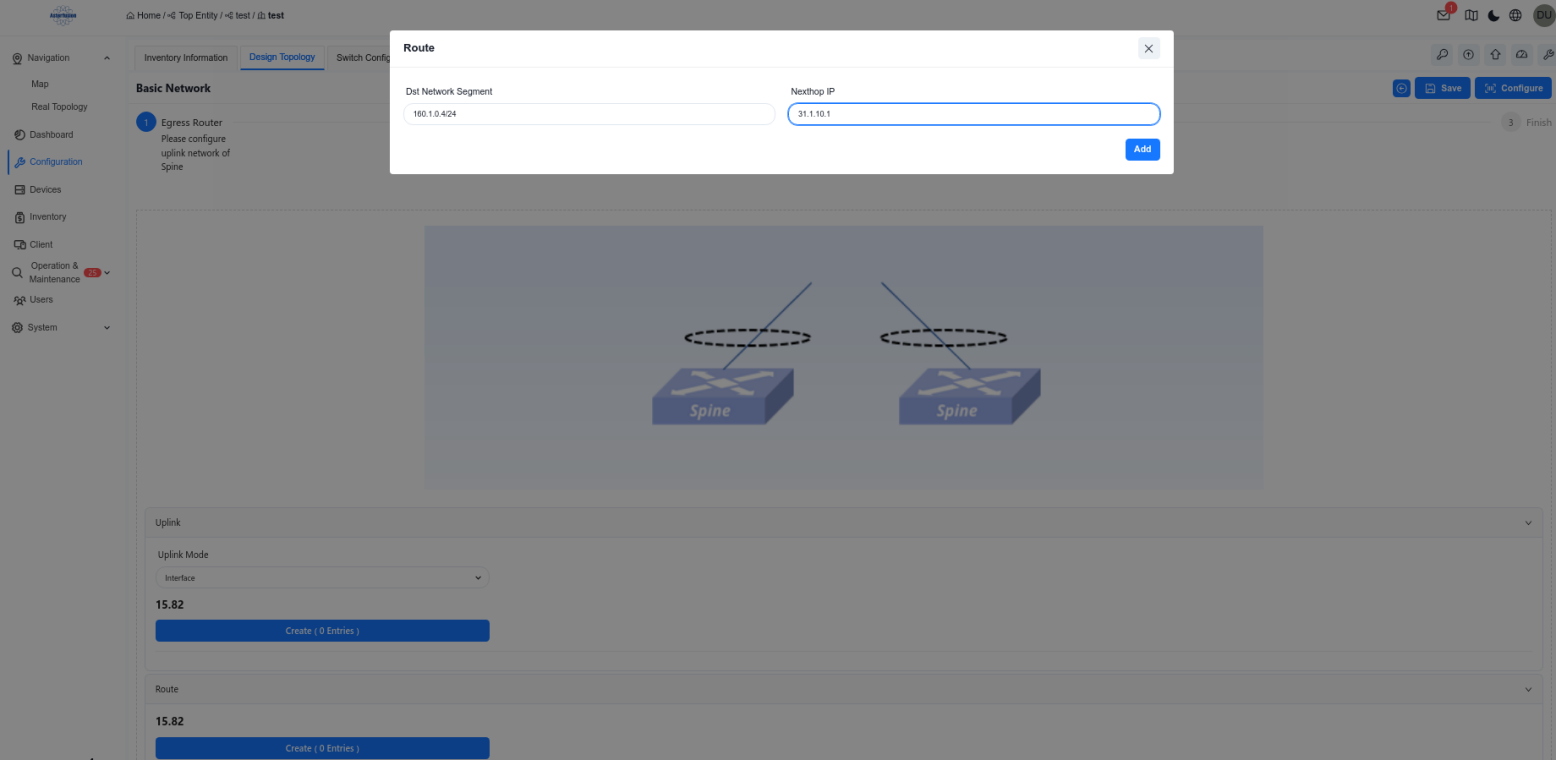 |
| Step 4 | The configuration of Device Management is consistent with the Egress route of [Small/Mid-Scale Network Deployment], please refer to the previous section to complete the configuration. |
Wired Service Configuration
Section titled “Wired Service Configuration”| Procedure | Description |
|---|---|
| Step 1 | Create Switch configuration |
Note
when selecting devices, Spine-type devices must also be added.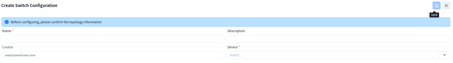 |
| Step 2 | Create service GW on Spine switch.
Configure DHCP Relay function:
|
| Step 2 | Create service GW on Spine switch.
Configure DHCP Relay function: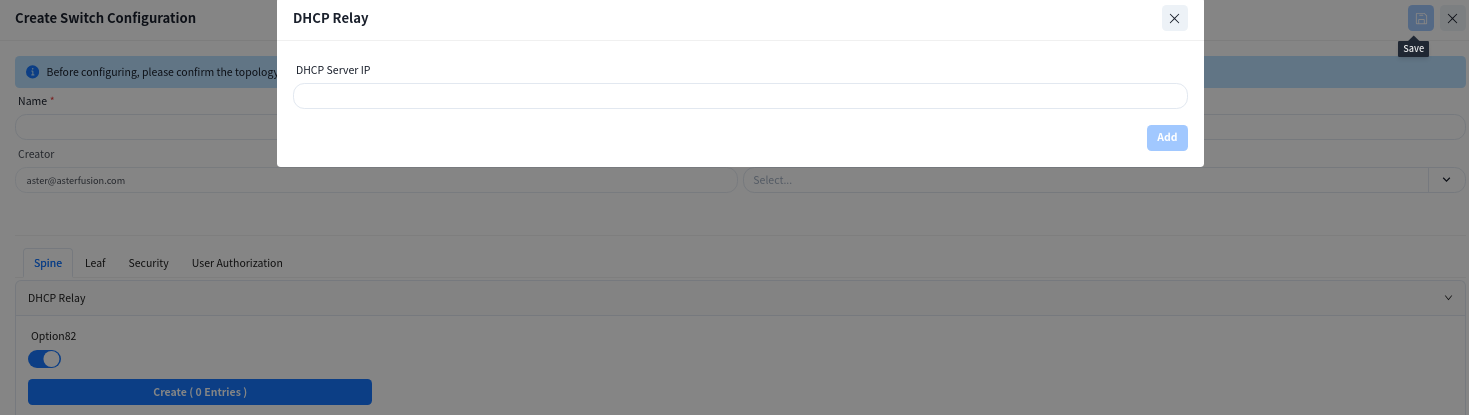 |
| Step 3 | Create service VLAN and GW IP
|
| Step 3 | Create service VLAN and GW IP 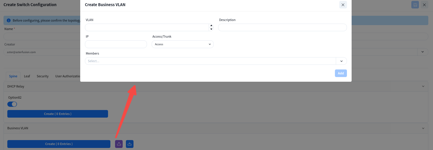 |
| Step 4 | Create Leaf switch configuration. On this interface, only the VLAN ID and member interfaces need to be specified, and all other configurations are generated by the controller.
|
| Step 4 | Create Leaf switch configuration. On this interface, only the VLAN ID and member interfaces need to be specified, and all other configurations are generated by the controller.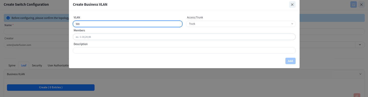 |
| Step 5
(Optional) | Create Service ACLs to configure access control lists between services in different network segments.
|
| Step 5
(Optional) | Create Service ACLs to configure access control lists between services in different network segments.
Note: This configuration takes effect on Spine devices, and VLAN isolation is applied between Leaf devices.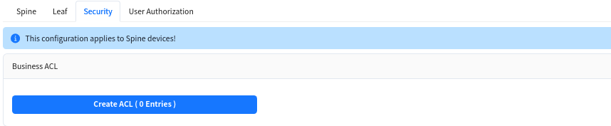 |
| Step 6 | The configuration of User Access Authentication is consistent with the Egress route of [Small/Mid-Scale Network Deployment], please refer to the previous section to complete the configuration. |
|
| Step 6 | The configuration of User Access Authentication is consistent with the Egress route of [Small/Mid-Scale Network Deployment], please refer to the previous section to complete the configuration. |
Wireless Service Configuration
Section titled “Wireless Service Configuration”The configuration of this part is consistent with the Egress route of [Small/Mid-Scale Network Deployment], please refer to the previous section to complete the configuration.
Configuration Release
Section titled “Configuration Release”The configuration of this part is consistent with the Egress route of [Small/Mid-Scale Network Deployment], please refer to the previous section to complete the configuration.
Open Cloud Connect
Section titled “Open Cloud Connect”Open cloud connect scenarios support users to configure access switches in bulk. The gateway is deployed on aggregation or access devices. Suitable for scenarios where there are already aggregation devices or access layer expansion in the park, providing two classic modes: layer 2 forwarding and access layer gateway.
Wired Service Configuration
Section titled “Wired Service Configuration”| Procedure | Description |
|---|---|
| Step 1 | Create switch configuration without design topology |
| Step 2 | Create static route and choice uplink interface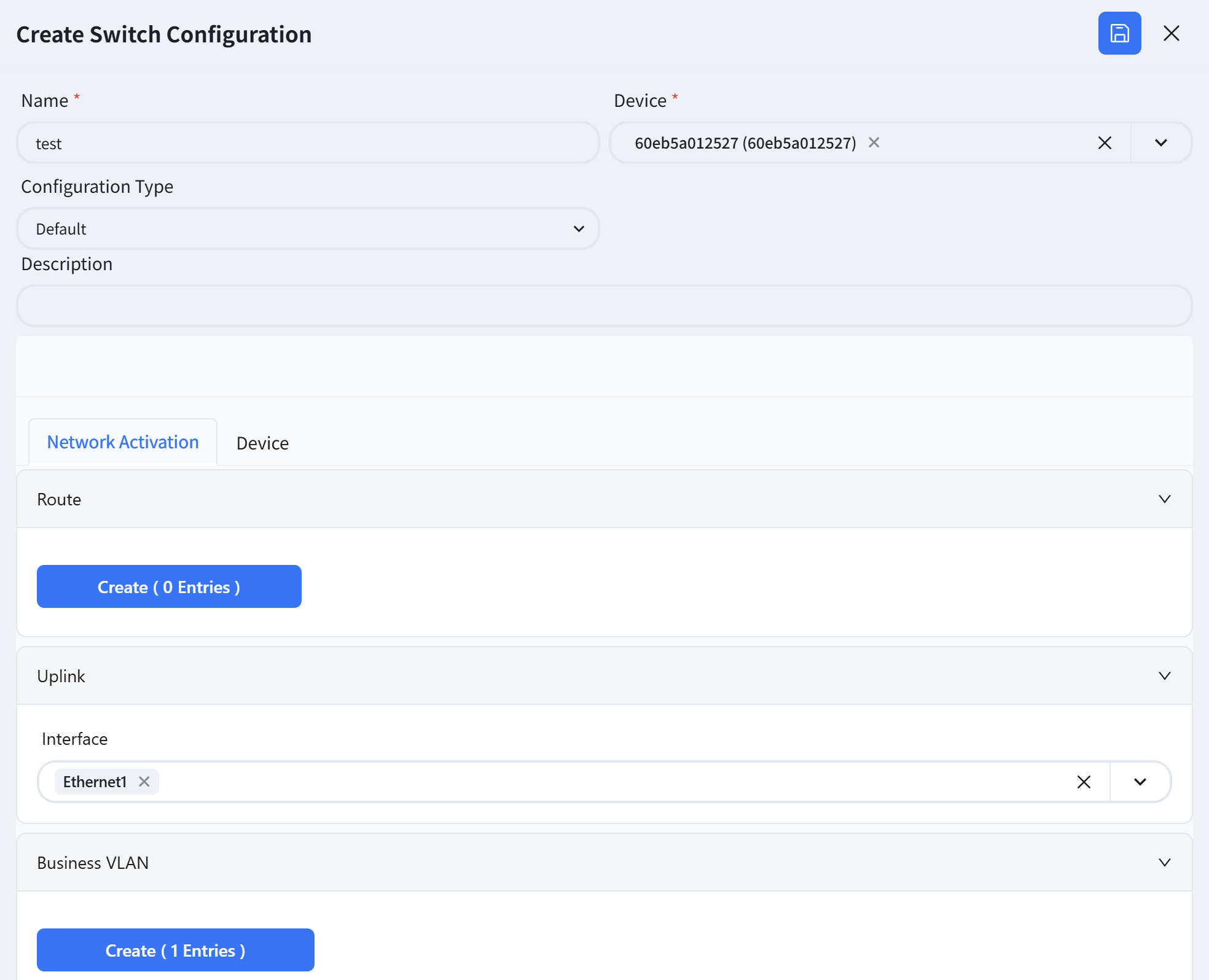 |
| Step 3 | Create a business VLAN. |
There has two way to configuration VLANif interface IP address
DHCP Request: The VLAN interface will act as a DHCP client, sending DHCP request packets to the DHCP server to obtain an IP address.
Static Configure: In the static configuration mode, an IP address range is specified, and IP addresses are assigned sequentially to all switches that apply this configuration.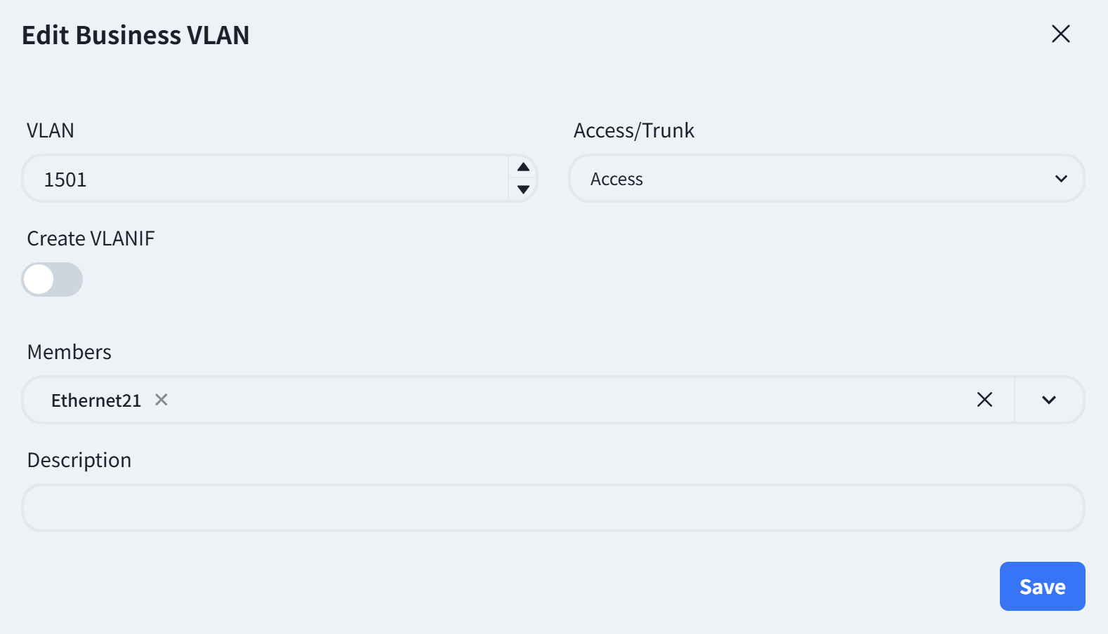 |
|
Wireless Service Configuration
Section titled “Wireless Service Configuration”The configuration of this part is consistent with the Egress route of [Small/Mid-Scale Network Deployment], please refer to the previous section to complete the configuration.
Configuration Release
Section titled “Configuration Release”The open cloud connect scenario does not require the issuance of basic network configuration, and the rest of this part is consistent with the Egress route of [Small/Mid-Scale Network Deployment], please refer to the previous section to complete the configuration.