G-SID Compression-Based SRv6 Inter-AS Option B Configuration
此内容尚不支持你的语言。
Introduction
Section titled “Introduction”In cross-data-center or cross-carrier networks, each network is typically managed as an independent autonomous system (AS). Inter-AS services require not only the exchange of VPN routes between ASs, but also that service traffic is forwarded along the intended path. SRv6 carries forwarding instructions in IPv6 addresses, providing a unified transport for inter-AS L3VPN services and supporting control over the transport path.
This case presents an SRv6 inter-AS networking solution that combines Inter-AS Option B, G-SID, and SR-TE Policy. VPN routes are exchanged between ASs using Option B; the ingress PE selects the inter-AS path based on the SR-TE Policy associated with the service route; and G-SID compresses the SIDs in the path to reduce packet encapsulation overhead.
Technical Principles
Section titled “Technical Principles”Inter-AS Option B Solution
Section titled “Inter-AS Option B Solution”In the Inter-AS Option B solution, each AS maintains its own intra-AS underlay network independently, and ASBRs exchange VPN routes via MP-eBGP so that service sites in different ASs can communicate. Inter-AS VPN routes are passed through the ASBRs to the ingress PE, which performs SRv6 encapsulation on service packets based on the route information; the egress PE decapsulates the packets and forwards them to the destination VPN.
G-SID Encapsulation
Section titled “G-SID Encapsulation”In traditional SRv6, each SID occupies 128 bits. As the number of segments in a path grows, the SID list increases packet header overhead.
G-SID uses the address portion shared by multiple nodes as the Common Block, and uses shorter SIDs to represent individual nodes or forwarding behaviors. Four G-SIDs (4 x 32 bits) can be encoded in a single IPv6 address (128 bits). When a packet passes through a node, the node processes the current SID and updates the packet’s IPv6 destination address so that the packet continues to be forwarded along the specified path.
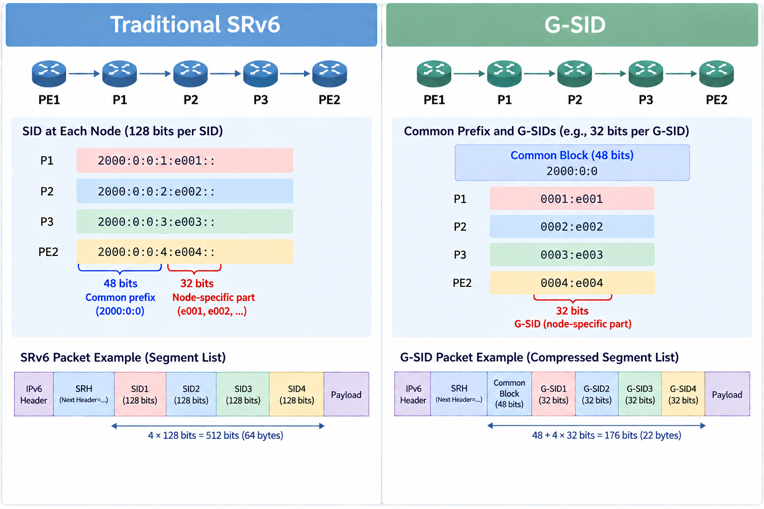
In this case, G-SID compressed encoding is used in the Segment List of the SR-TE Policy to reduce the encapsulation overhead of the inter-AS explicit path.
Typical Configuration Example
Section titled “Typical Configuration Example”Network Topology
Section titled “Network Topology”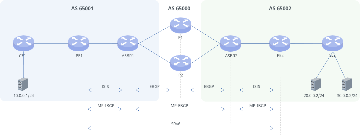
IP Address Plan
Section titled “IP Address Plan”| Link | Local End | IP | Remote End | IP |
|---|---|---|---|---|
| CE1-PE1 | CE1 Ethernet1 | 100.0.1.1/24 | PE1 Ethernet | 100.0.1.2/24 |
| PE1-ASBR1 | PE1 Ethernet2 | 1002::1/64 | ASBR1 Ethernet2 | 1002::2/64 |
| ASBR1-P1 | ASBR1 Ethernet3 | 1003::1/64 | P1 Ethernet1 | 1003::2/64 |
| ASBR1-P2 | ASBR1 Ethernet4 | 1010::2/64 | P2 Ethernet1 | 1010::1/64 |
| ASBR2-P1 | ASBR2 Ethernet3 | 2003::2/64 | P1 Ethernet2 | 2003::1/64 |
| ASBR2-P2 | ASBR2 Ethernet4 | 2010::2/64 | P2 Ethernet2 | 2010::1/64 |
| ASBR2-PE2 | ASBR2 Ethernet2 | 2002::1/64 | PE2 Ethernet2 | 2002::2/64 |
| PE2-CE2 | PE2 Ethernet1 | 200.0.0.2/24 | CE2 Ethernet1 | 200.0.0.1/24 |
Loopback Address and Locator Prefix Plan
Section titled “Loopback Address and Locator Prefix Plan”| Device | Loopback0 | Locator Prefix | SID | Behavior |
|---|---|---|---|---|
| ASBR1 | 2000::1/64 | 2000::/64 | 2000::f011:0:0:0/80 | End |
| P1 | 2000:0:0:1::/64 | 2000:0:0:1::/64 | 2000:0:0:1:e001::/80 | End |
| P2 | 2000:0:0:2::/64 | 2000:0:0:2::/64 | 2000:0:0:2:e001::/80 | End |
| ASBR2 | 2000:0:0:3::/64 | 2000:0:0:3::/64 | 2000:0:0:3:fe00::/80 | End |
| PE1 | 2000:0:0:4::/64 | 2000:0:0:4::/64 | 2000:0:0:4:e002::/80 | End.DT4 |
| PE1 | 2000:0:0:4::/64 | 2000:0:0:4::/64 | 2000:0:0:4:e000::/80 | End |
| PE2 | 2000:0:0:5::/64 | 2000:0:0:5::/64 | 2000:0:0:5:e003::/80 | End.DT4 |
| PE2 | 2000:0:0:5::/64 | 2000:0:0:5::/64 | 2000:0:0:5:e000::/80 | End |
Configuration Roadmap
Section titled “Configuration Roadmap”- Enable IPv6 forwarding on all interfaces of the PE, ASBR, and P devices, and configure interface IPv6 addresses
- Enable IS-IS within each AS and configure the level
- Configure VRFs on PE1 and PE2
- Establish EBGP peer relationships between ASBRs and P devices
- Establish MP-BGP peer relationships between PE1 and ASBR1, ASBR1 and ASBR2, and ASBR2 and PE2 to advertise VPN routes
- Enable SRv6 on the PE, ASBR, and P devices, and configure Locator prefixes and SIDs
- Configure route-maps to assign different Colors to different subnets
- Create SR-TE Policies matching the Colors
Service Configuration
Section titled “Service Configuration”Configure Interface and Loopback Addresses
Section titled “Configure Interface and Loopback Addresses”Enable IPv6 forwarding on each interface and configure IPv6 addresses. PE1 is used as an example; the configuration on other devices is similar and is not repeated here.
interface loopback 0 ip address 2000:0:0:4::1/64exit
interface ethernet 2 router-interface ip address 1002::1/64 ipv6 use-link-localexit
Configure IS-IS
Section titled “Configure IS-IS”Both AS 65001 and AS 65002 use IS-IS Level-1 internally to build the IPv6 underlay. PE1 and ASBR1 are used as examples; the configuration on PE2 and ASBR2 is similar and is not repeated here.
# Configure PE1
router isis test is-type level-1 net 10.0000.0000.0000.2222.00 redistribute ipv4 bgp level-1 redistribute ipv4 connected level-1 redistribute ipv6 bgp level-1 redistribute ipv6 connected level-1exit
interface ethernet 2 ip router isis test ipv6 router isis test isis metric level-1 2 isis network point-to-point no isis hello paddingexit
# Configure ASBR1
router isis test is-type level-1 net 10.0000.0000.0000.3333.00 redistribute ipv4 bgp level-1 redistribute ipv4 connected level-1 redistribute ipv6 bgp level-1 redistribute ipv6 connected level-1exit
interface ethernet 2 ip router isis test ipv6 router isis test isis network point-to-point no isis hello paddingexit
After the configuration is complete, verify that IS-IS is configured successfully as follows.
# Display IS-IS neighbor information (PE1 as an example).
show isis neighborArea testSystem Id Interface L State Holdtime SNPA ASBR1 eth 2 1 up 29 2230.6602.375cConfigure VRFs and CE Access
Section titled “Configure VRFs and CE Access”Create VRF 100 on both PEs and establish an IPv4 IBGP neighbor with the CE within the VRF. CE1 and PE1 are used as examples below; the configuration on CE2 and PE2 is similar.
# Configure CE1
interface ethernet 1router-interfaceip address 100.0.1.1/24exit
interface ethernet 3router-interfaceip address 10.0.0.2/24exit
router bgp 65001no bgp default ipv4-unicastno bgp ebgp-requires-policyneighbor 100.0.1.2 remote-as internaladdress-family ipv4 unicastneighbor 100.0.1.2 activateredistribute connectedexitexit
# Configure PE1
vrf 100exit
interface ethernet 1router-interfaceip address 100.0.1.2/24vrf 100exit
router bgp 65001 vrf 100bgp router-id 1.1.1.1no bgp default ipv4-unicastno bgp ebgp-requires-policyneighbor 100.0.1.1 remote-as internaladdress-family ipv4 unicastexport vpnimport vpnneighbor 100.0.1.1 activaterd vpn export 3:20rt vpn both 88:88exitexit
Configure EBGP Peers Between ASBRs and P Devices
Section titled “Configure EBGP Peers Between ASBRs and P Devices”Configure EBGP peers between ASBRs and P devices. ASBR1 and P1 are used as examples; the configuration between ASBR1 and P2, P1 and ASBR2, and P2 and ASBR2 is similar.
# Configure ASBR1
router bgp 65001 no bgp default ipv4-unicast no bgp ebgp-requires-policy neighbor 1003::2 remote-as 65000 neighbor 1003::2 capability extended-nexthop neighbor 1003::2 ebgp-multihop 10 neighbor 1003::2 update-source 1003::1 address-family ipv4 unicast neighbor 1003::2 activate redistribute connected exit address-family ipv6 unicast neighbor 1003::2 activate redistribute connected redistribute isis exitexit# Configure P1
router bgp 65000 no bgp default ipv4-unicast no bgp ebgp-requires-policy egress-engineering enable neighbor 1003::1 remote-as 65001 neighbor 1003::1 capability extended-nexthop neighbor 1003::1 ebgp-multihop 10 neighbor 1003::1 update-source 1003::2 address-family ipv4 unicast neighbor 1003::1 activate redistribute connected exit address-family ipv6 unicast neighbor 1003::1 activate redistribute connected exitexitConfigure MP-EBGP/MP-IBGP Peers
Section titled “Configure MP-EBGP/MP-IBGP Peers”Using PE1 and ASBR1 as an example, configure MP-IBGP peers to advertise VPN routes within the AS. The configuration between PE2 and ASBR2 is similar.
# Configure PE1
router bgp 65001 bgp router-id 1.1.1.1 no bgp default ipv4-unicast no bgp ebgp-requires-policy neighbor 2000::1 remote-as 65001 neighbor 2000::1 capability extended-nexthop neighbor 2000::1 update-source 2000:0:0:4::1 address-family ipv4 unicast redistribute connected exit address-family ipv4 vpn neighbor 2000::1 activate exit address-family ipv6 unicast redistribute connected redistribute isis exitexit# Configure ASBR1
router bgp 65001 neighbor 2000:0:0:4::1 remote-as 65001 neighbor 2000:0:0:4::1 capability extended-nexthop neighbor 2000:0:0:4::1 update-source 2000::1 address-family ipv4 vpn neighbor 2000:0:0:4::1 activate neighbor 2000:0:0:4::1 next-hop-self exitexitConfigure the MP-EBGP peer between ASBR1 and ASBR2 to pass VPN routes across ASs.
# Configure ASBR1
router bgp 65001 neighbor 2000:0:0:3::1 remote-as 65002 neighbor 2000:0:0:3::1 capability extended-nexthop neighbor 2000:0:0:3::1 ebgp-multihop 10 neighbor 2000:0:0:3::1 update-source 2000::1 address-family ipv4 vpn neighbor 2000:0:0:3::1 activate neighbor 2000:0:0:3::1 next-hop-self exitexit# Configure ASBR2
router bgp 65002 neighbor 2000::1 remote-as 65001 neighbor 2000::1 capability extended-nexthop neighbor 2000::1 ebgp-multihop 10 neighbor 2000::1 update-source 2000:0:0:3::1 address-family ipv4 vpn neighbor 2000::1 activate neighbor 2000::1 next-hop-self exitexitRun show ipv6 bgp summary to check the BGP neighbor status of the device.
# Check the IPv6 BGP neighbor status on ASBR1.
show ip bgp ipv6 summary
IPv6 Unicast Summary:BGP router identifier 240.127.1.1, local AS number 65001 VRF default vrf-id 0BGP table version 50 RIB entries 15, using 1920 bytes of memory Peers 2, using 48 KiB of memory
Neighbor  V AS MsgRcvd MsgSent TblVer InQ OutQ Up/Down State/PfxRcd PfxSnt Desc1003::2   4 65000 3267   3287     50     0   0   01:12:09   5    8           N/A1010::1   4 65000 1716   1729     50     0   0   1d04h03m   5    8           N/A
Total number of neighbors 2
IPv6 VPN Summary:BGP router identifier 240.127.1.1, local AS number 65002 VRF default vrf-id 0BGP table version 0 RIB entries 3, using 384 bytes of memory Peers 2, using 48 KiB of memory
Neighbor       V AS   MsgRcvd MsgSent TblVer InQ OutQ Up/Down State/PfxRcd PfxSnt Desc2000:0:0:3::1 4 65002 3227    3268     0      0   0   01:13:52     0          0     N/A2000:0:0:4::1 4 65001 17       19      36     0   0   00:04:21     0           0     N/A
Configure SRv6 Capabilities
Section titled “Configure SRv6 Capabilities”Using PE1 as an example, configure the SRv6 Locator and set the encapsulation format to gsid-f4832.
After the Locator prefix is configured, SIDs are generated automatically. SIDs can also be configured statically using the sid sid locator locator-name behavior {End/End.X/End.DT4/End.DT6} command. The configuration on PE2, ASBR1, ASBR2, P1, and P2 is similar:
# Configure PE1
segment-routing srv6 locators locator pe1 format gsid-f4832 prefix 2000:0:0:4::/64 block-len 48 node-len 16 arg-len 48 exit exit exitexitEnable SRv6 in the IS-IS process and associate the Locator. The configuration on PE2, ASBR1, and ASBR2 is similar:
# Configure PE1
router isis test segment-routing srv6 locator pe1 exitexitEnable SRv6 in the BGP process and associate the local Locator ID so that BGP uses this Locator for SRv6 VPN services. The configuration on PE2, ASBR1, and ASBR2 is similar:
# Configure PE1
router bgp 65001 segment-routing srv6  locator pe1 exitexit
router bgp 65001 vrf 100 address-family ipv4 unicast  sid vpn export auto exitexit
If SIDs are allocated dynamically, run the show segment-routing srv6 local sid command after the configuration to check SID allocation.
Configure Route-map
Section titled “Configure Route-map”Taking the route for subnet 20.0.0.0/24 advertised from PE2 to PE1 as an example, create a route-map that sets the color of routes matching this subnet to 100.
ip prefix-list test seq 10 permit 20.0.0.0/24route-map test permit 10 match ip address prefix-list test set extcommunity color 00:100exitrouter bgp 65002 vrf 100 address-family ipv4 unicast route-map vpn export test exit exitAfter the configuration is complete, verify that the VPN routes carry the specified Color as follows.
# View VPN route information on ASBR2.
show bgp ipv4 vpnBGP table version is 28, local router ID is 6.6.6.6, vrf id 0Default local pref 100, local AS 65002Status codes:  s suppressed, d damped, h history, u unsorted, * valid, > best, = multipath,               i internal, r RIB-failure, S Stale, R RemovedNexthop codes: @NNN nexthop's vrf id, < announce-nh-selfOrigin codes:  i - IGP, e - EGP, ? - incompleteRPKI validation codes: V valid, I invalid, N Not found
     Network          Next Hop            Metric LocPrf Weight PathRoute Distinguisher: 3:20 *>i 10.0.0.0/24      2000:0:0:3::1                 100      0 65001 ?    UN=2000:0:0:3::1 EC{88:88} label=917536 sid=2000:0:0:4:: sid_structure=[48,16,16,48] type=bgp, subtype=0 *>i 10.1.0.1/32      2000:0:0:3::1                 100      0 65001 ?    UN=2000:0:0:3::1 EC{88:88} label=917536 sid=2000:0:0:4:: sid_structure=[48,16,16,48] type=bgp, subtype=0 *>  20.0.0.0/24      200.0.1.2@15<            0    100      0 ?    UN=200.0.1.2 EC{88:88 Color:00:100} label=917552 sid=2000:0:0:5:: sid_structure=[48,16,16,48] type=bgp, subtype=5 *>i 100.0.1.0/24     2000:0:0:3::1                 100      0 65001 ?UN=2000:0:0:3::1 EC{88:88} label=917536 sid=2000:0:0:4:: sid_structure=[48,16,16,48] type=bgp, subtype=0
Displayed 4 routes and 4 total paths
Configure TE-Policy
Section titled “Configure TE-Policy”Taking services for subnet 20.0.0.0/24 as an example, create a TE-Policy that specifies the forwarding path for this subnet as: PE1 -> ASBR1 -> P1 -> ASBR2 -> PE2.
# Configure the TE-policy for color 100 on PE1.
segment-routing traffic-eng segment-list testpath index 3 ipv6-address 2000::f011:0:0:0 compress csid-len 32 block-len 48 index 5 ipv6-address 2000:0:0:1:e001:: compress csid-len 32 block-len 48 index 10 ipv6-address 2000:0:0:3:fe00:: compress csid-len 32 block-len 48 index 15 ipv6-address 2000:0:0:5:e001:: compress csid-len 32 block-len 48 exit policy test color 100 endpoint 2000::1 candidate-path 100 preference 100 explicit segment-list 100 testpath exit exitAfter the configuration is complete, check the route information as follows.
# View route information on PE1.
show ip route vrf allCodes: K - kernel route, C - connected, L - local, S - static,       R - RIP, O - OSPF, I - IS-IS, B - BGP, E - EIGRP, N - NHRP,       T - Table, v - VNC, V - VNC-Direct, A - Babel, F - PBR,       f - OpenFabric, t - Table-Direct,       > - selected route, * - FIB route, q - queued, r - rejected, b - backup       t - trapped, o - offload failure
IPv4 unicast VRF 100:B>* 10.0.0.0/24 [200/0] via 100.0.1.1, eth 1, weight 1, 01:54:02B>* 10.1.0.1/32 [200/0] via 100.0.1.1, eth 1, weight 1, 01:54:02B>  20.0.0.0/24 [200/0] via 2000::1 (vrf default) (recursive), SR-TE color 100, seg6 2000::f011:0:0:0,2000:0:0:1:e001::,2000:0:0:3:fe00::,2000:0:0:5:e001::,2000:0:0:5:e003::, weight 1, 00:08:57  *                       via fe80::2030:66ff:fe02:375c, eth 2 (vrf default), seg6 2000::f011:0:0:0,5:e003:5:e001:3:fe00:1:e001, encap behavior H.Encaps.Red, weight 1, 00:08:57B   100.0.1.0/24 [200/0] via 100.0.1.1 inactive, weight 1, 01:25:15C>* 100.0.1.0/24 is directly connected, eth 1, weight 1, 01:54:06
Verification
Section titled “Verification”- Ping PC2 (20.0.0.2) on the right from PC1 to verify inter-AS connectivity for Color 100 services.
PC1> ping -a 20.0.0.2
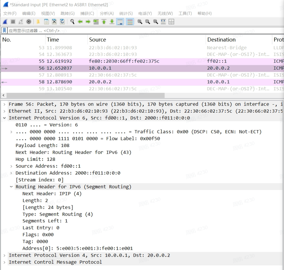
84 bytes from 20.0.0.2 icmp_seq=1 ttl=60 time=39 ms84 bytes from 20.0.0.2 icmp_seq=2 ttl=60 time=27 ms84 bytes from 20.0.0.2 icmp_seq=3 ttl=60 time=47 ms84 bytes from 20.0.0.2 icmp_seq=4 ttl=60 time=27 ms84 bytes from 20.0.0.2 icmp_seq=5 ttl=60 time=37 ms84 bytes from 20.0.0.2 icmp_seq=6 ttl=60 time=35 ms- During the ping test, capture service packets between PE1 and ASBR1 and between ASBR1 and P1 to confirm G-SID encapsulation.
# Packets captured at the PE1 egress:
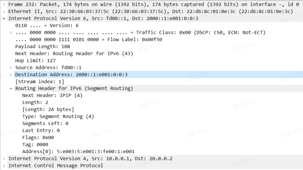
# Packets captured at the ASBR1 egress: