
Large/Mid-Scale Campus Usage Guide
This solution is designed for medium to large-scale campus networks, adopting a Spine-Aggregation-Leaf fully layered three-tier network architecture. It leverages a controller for automated management and intelligent operations. The network is divided into a default access zone and a server zone, utilizing key technologies such as distributed gateways and MC-LAG to provide high-performance and highly reliable network connectivity for large-scale terminal access and high-availability server clusters.
Centrally Intelligent Management Core
The controller automatically translates business intents into device configurations through a graphical interface and deploys them accurately, completely eliminating the traditional tedious process of configuring devices one by one via command-line interface. It offers full lifecycle management, including device onboarding, monitoring, and diagnostics, enabling network automation and high reliability.
Elastic and Reliable Network Backbone
Ultimate Scalability: Horizontal expansion at the aggregation layer supports the integration of large-scale Leaf switches, effortlessly accommodating future network growth.
Flexible Gateway Deployment: Distributed service gateways can be deployed at the Leaf layer, confining service traffic to the access layer. This significantly enhances forwarding efficiency and network reliability while effectively reducing the burden on upper-layer devices.
Scenario-Optimized Access Technologies
Leaf Distributed Gateways: Serve wired and wireless terminals in the default access zone. The gateway is lowered to the access Leaf, cross-subnet communication for terminals no longer needs to traverse the core layer, significantly reducing latency and enabling fault domain isolation.
Leaf MC-LAG: Provides high-availability Layer 2 access for the server zone. Two Leaf switches are virtualized into a single logical device via MC-LAG to connect with servers, achieving link-level and device-level load balancing and seamless failover. This eliminates loops while ensuring uninterrupted continuity for critical business operations..
Scheme Design
Section titled “Scheme Design”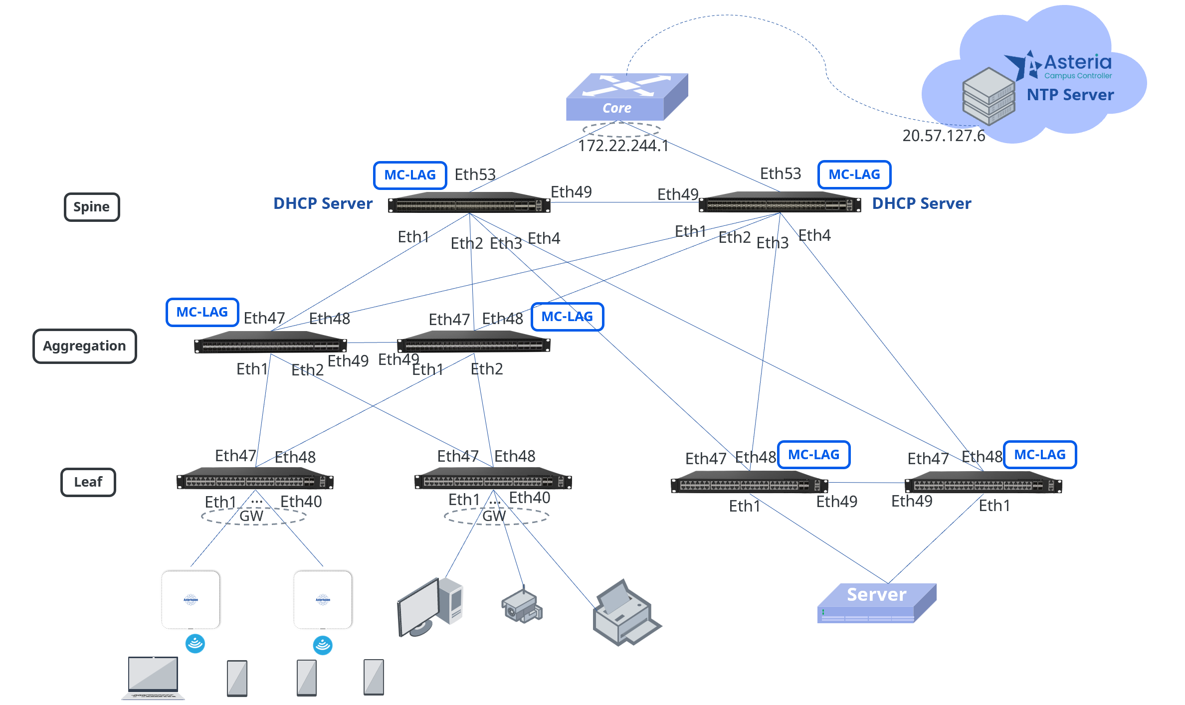
This medium to large-scale campus employs a full three-tier Spine-Aggregation-Leaf network architecture, divided into a default access zone and a server zone.
Default Access Zone:
Leaf1 and Leaf2 function as distributed gateways, with Leaf1 dedicated to connecting APs and wireless terminals, and Leaf2 managing wired terminals. Horizontal scaling at the aggregation layer (Agg1, Agg2) ensures high availability and load balancing. MC-LAG operates between the Spine and aggregation devices to guarantee link reliability.
Server Zone:
Leaf3 and Leaf4 connect to servers in pure Layer 2 mode via MC-LAG technology, with gateways centrally deployed on the Spine devices. This simplifies network management in the server zone and enhances forwarding efficiency.
Management Network:
Spine devices and Leaf devices (Leaf1, Leaf2) in the default service zone are Layer 3 devices, using Loopback addresses as their in-band management addresses.
Aggregation layer devices and Leaf devices (Leaf3, Leaf4) in the server zone are Layer 2 devices. In-band management addresses are assigned to each Layer 2 device from the address range provided in the basic network configuration, with all gateways deployed on Spine1.
DHCP Deployment:
DHCP Servers are deployed on both Spine devices and are automatically configured as a DHCP Failover pair via the controller, ensuring high availability of address services.
Controller Deployment:
The controller is cloud-based and enables centralized policy deployment, configuration management, and status monitoring for all network devices through a graphical interface, significantly improving operational efficiency.
Foundation Link Data Planning
| Device | Interface | IP Address |
|---|---|---|
| Spine1 | Ethernet53 | 172.22.244.10/24 |
| Loopback0 | 172.22.252.51/32 | |
| Spine2 | Ethernet53 | 172.22.244.11/24 |
| Loopback0 | 172.22.252.52/32 | |
| Leaf1 | Loopback0 | 172.22.252.53/32 |
| Leaf2 | Loopback0 | 172.22.252.54/32 |
Service Network Data Planning
| Service Type | IP Segment | Gateway | Service VLAN | SSID |
|---|---|---|---|---|
| Wireless Service | 180.10.0.0/24 | 180.10.0.1/24 | 1080 | New SSID |
| Wired Service | 180.10.1.0/24 | 180.10.1.1/24 | 1081 | |
| AP Management | 180.10.2.0/24 | 180.10.2.1/24 | 1082 | |
| Server Zone Service | 180.10.15.0/24 | 180.10.15.1/24 | 1501 | |
| Agg Management | 172.22.200.0/24 | 172.22.200.1/24 | ||
| Server Zone Leaf Management | 172.22.201.0/24 | 172.22.201.1/24 |
Device Import
Section titled “Device Import”Administrators can create or import devices in bulk to specified sites/organizations. When an added inventory device connects to the controller and comes online, the controller will automatically assign it to the designated organization/site based on its MAC address.
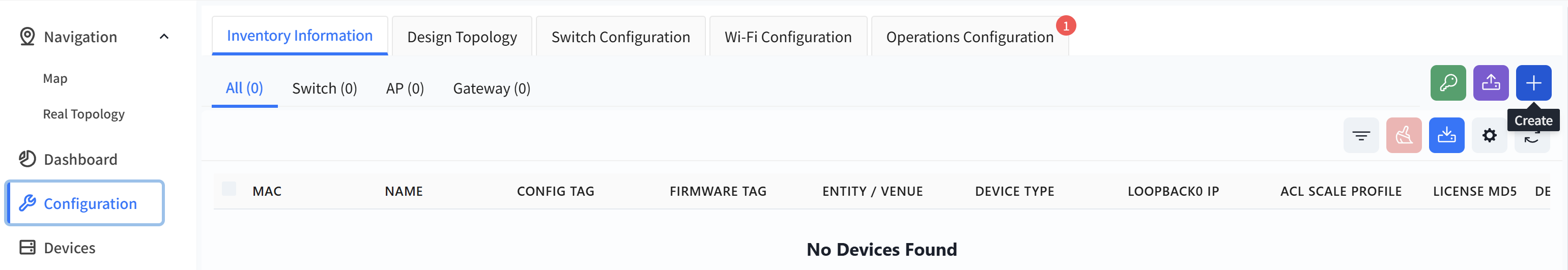
Add devices one by one.
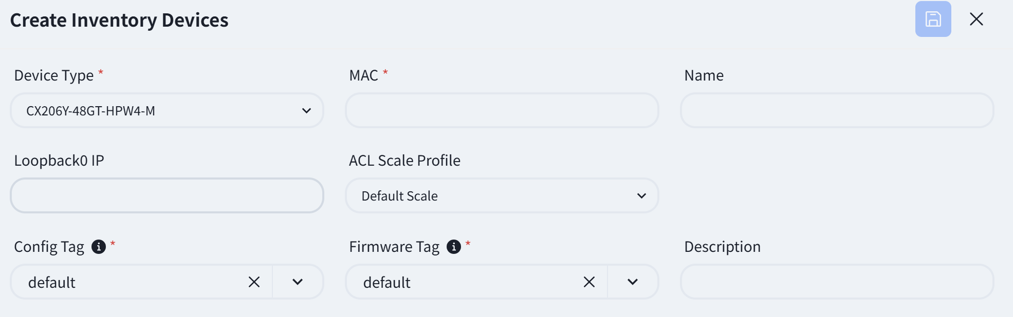
Click [Configuration] - [Inventory Information] - [+] to create an inventory device.
Fill in the relevant information as prompted on the page
Import via Excel
Click [Upload Devices]
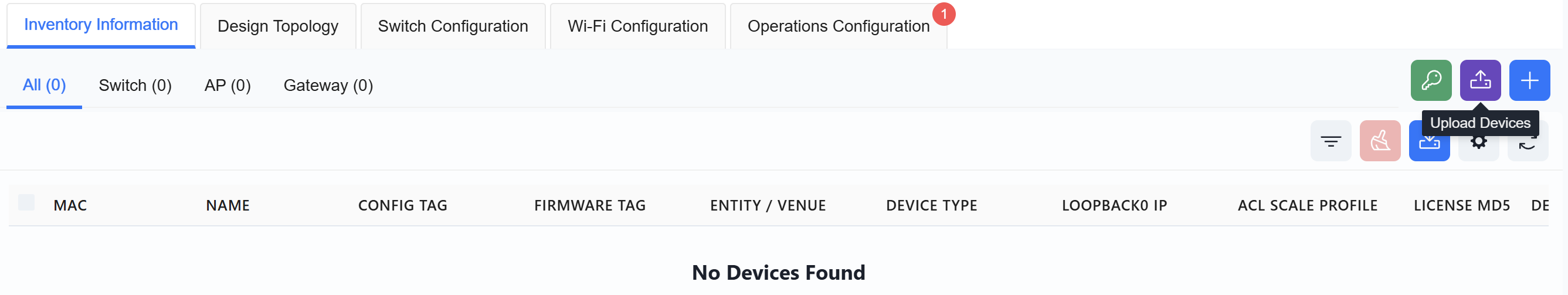
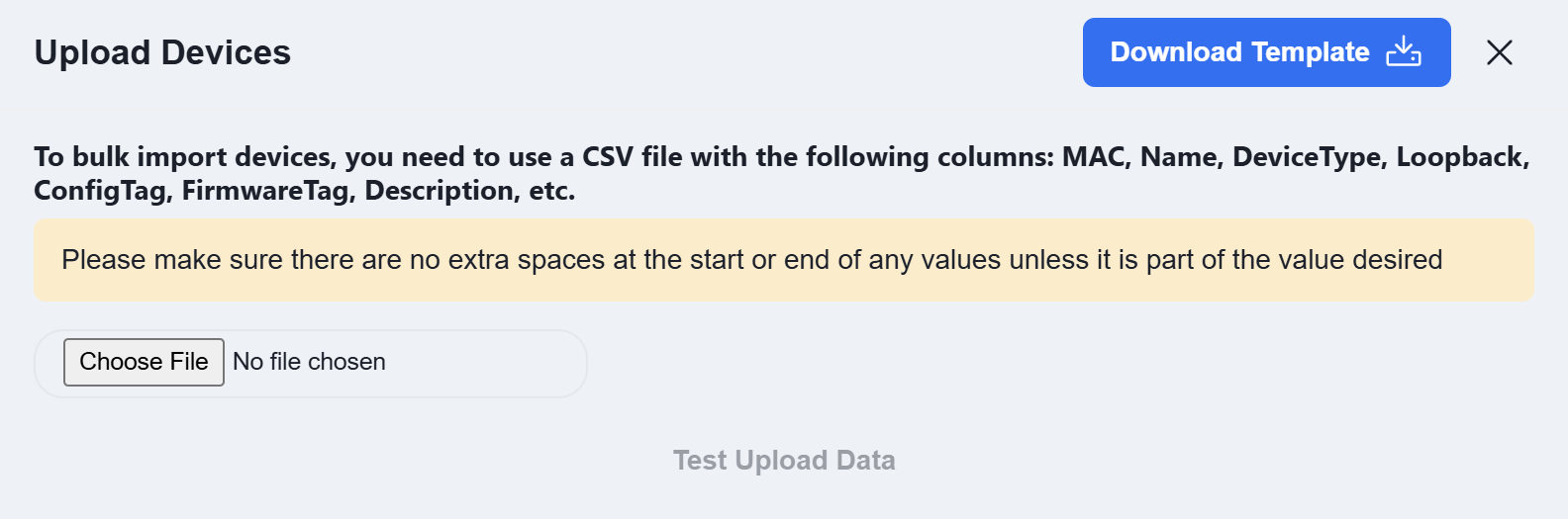
Click [Download Template] and enter the information for the devices to be added to the inventory according to the template’s specifications.
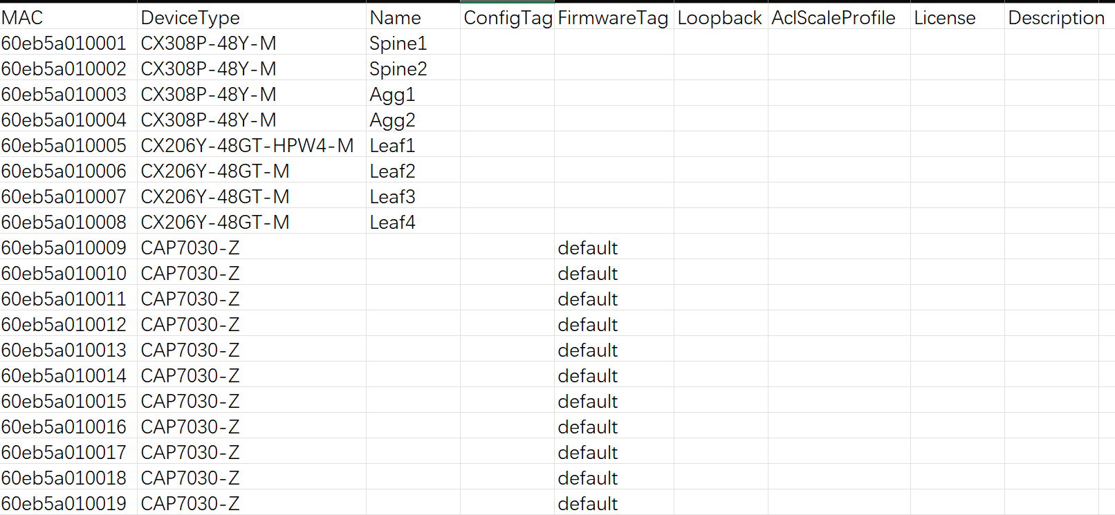
MAC: The device’s MAC address. This information is typically found on the device’s label.
Device Type: The device model.
Name: The device hostname. By default, it is the device’s MAC address.
ConfigTag: After an AP connects to the controller, it will automatically pull the configuration file corresponding to this tag. By default, the tag value is default.
FirmwareTag: When performing firmware upgrades, devices requiring an upgrade can be filtered based on their firmware tag type. By default, the tag value is default.
Loopback: The device’s loopback address. For all devices operating at Layer 3, this address serves as the device’s in-band management address.
AclScaleProfile: Optional values are default or large-scale. By default, the value is default.
License: The AP’s license file. For bulk imports, you can either enter the JSON-formatted license file content directly in the Excel sheet, or add all devices to inventory first and then import the license files in bulk afterward.
Description: Descriptive information about the device.
Click [Choose File] to upload the completed template, then click [Test Upload Data]. The controller will automatically check if the uploaded data complies with the specifications and display the results in the test report.
Once completed, users can view the created devices in the [Inventory Information] view.
Service Configuration
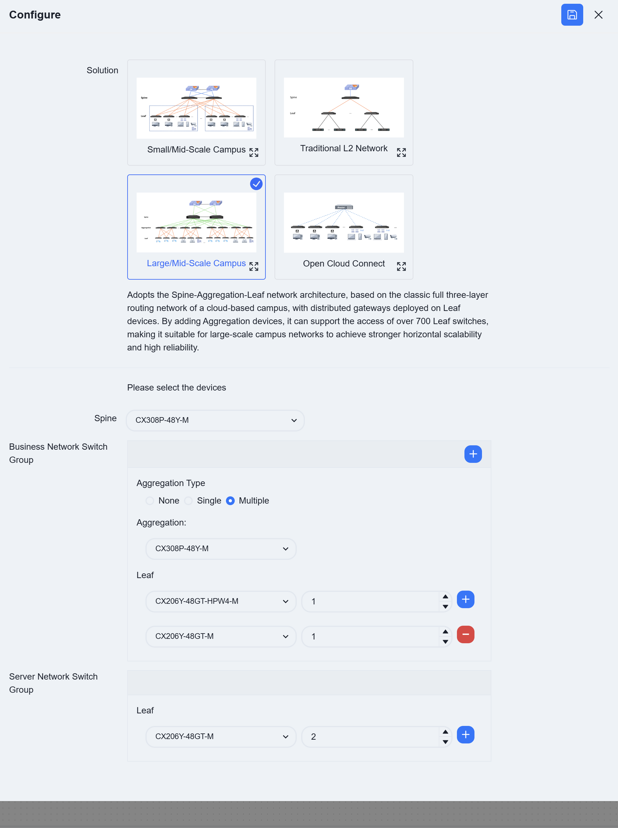
Section titled “Service Configuration”Click [Design Topology] to enter the corresponding page, select the Large/Mild-Scale campus deployment, fill in the required device models and quantities according to device roles, and then click [Save] to finish the network topology pre-planning. The controller will generate the network topology based on the entered information.
Generated topology:
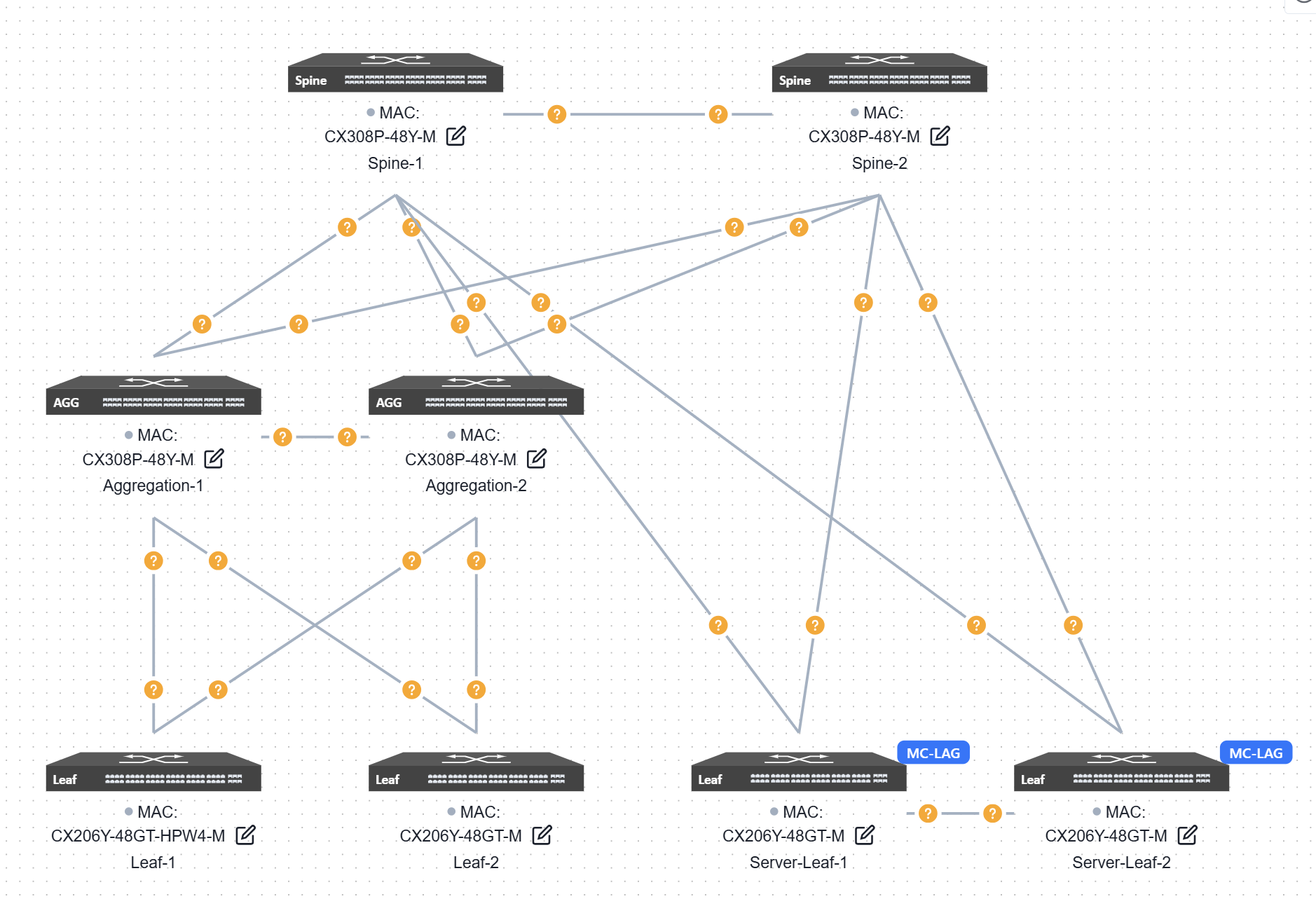
Users can click the [Edit] button on the device end and fill in the corresponding information in the slide-out panel on the right.
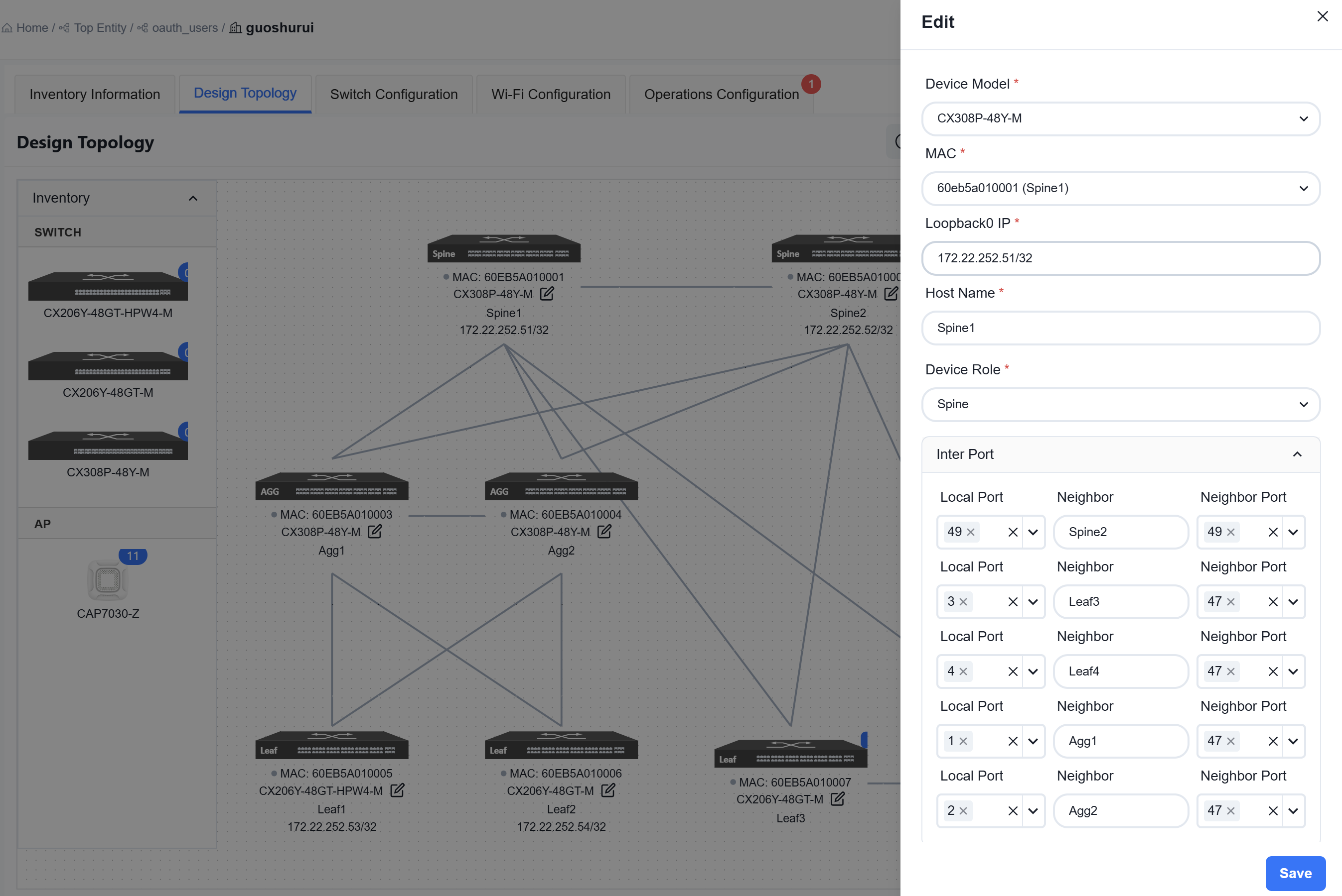
MAC: Uniquely select a device via its MAC address.
Loopback0 IP: Configure the IP address for the device’s Loopback0 interface, which will be used for in-band management of the device.
Hostname: Configure the hostname of the device.
Device role: Assign the device role as Spine or Leaf.
Inter Port:
- Neighbor Port: The interface on the peer device interconnected with the current device’s local interface.
- Neighbor: Select the peer device connected to the local interface.
- Local Port: The interface on the current device.
Upon completing all configurations, click [Save] in the upper right corner of the page, then select [Confirm] in the pop-up window.
Basic Network
Section titled “Basic Network”Click the top right corner [Basic Network]

Business Network
Section titled “Business Network”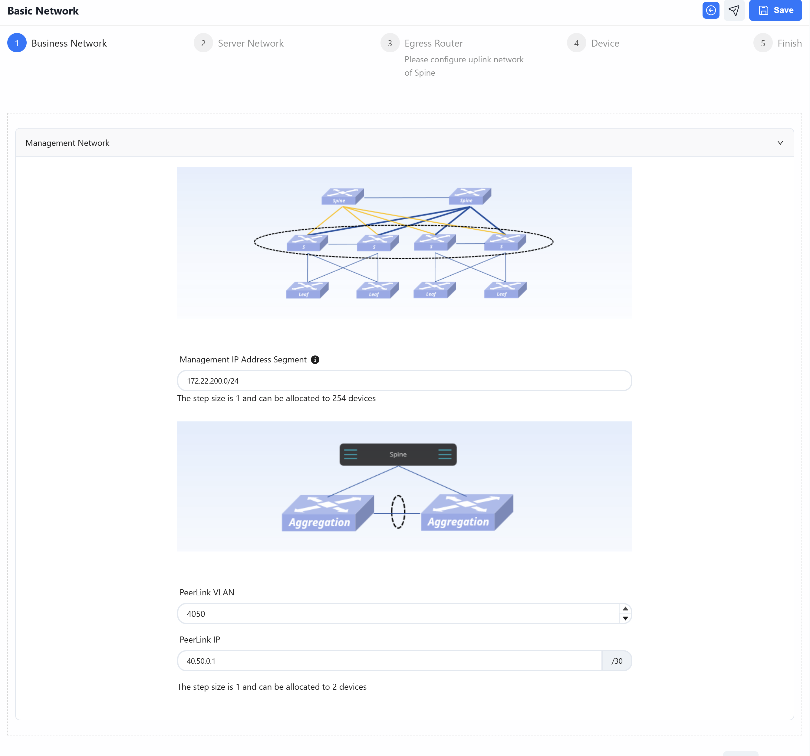
Management Address Segment: Configure an in-band management network for convergence devices. Since both Spine and Leaf devices are Layer 3 devices, the Loopback0 address can be used for in-band management. However, convergence devices are Layer 2 devices and require a VLAN interface to serve as the in-band management interface. The controller can assign an in-band management address to each convergence device based on the address segment entered by the user.
PeerLink VLAN: Configure a PeerLink VLAN for convergence devices. The directly connected interfaces between two devices are referred to as peer-link interfaces, which are primarily used for transmitting protocol packets and forwarding traffic in the event of a failure. The VLAN dedicated to the PeerLink interface is the PeerLink VLAN.
PeerLink IP: Configure an IP address on the PeerLink VLAN interface. After setting the PeerLink IP, the device knows which IP address to send control packets to for communication with the peer device. The IP addresses of the two peer convergence devices must be within the same subnet.
Server Network
Section titled “Server Network”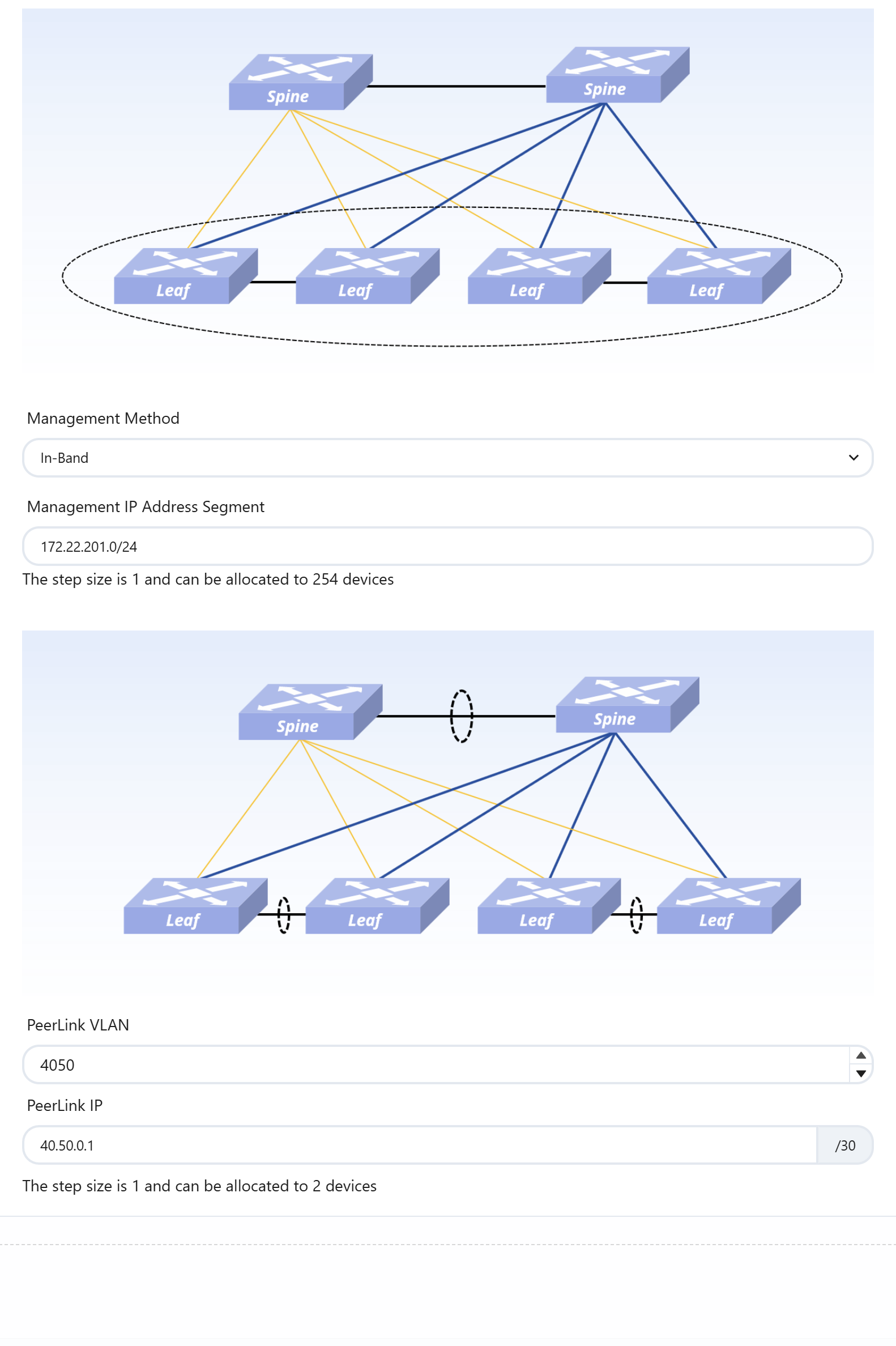
Configure the in-band management network for the server area leaf devices. Configure the PeerLink interface VLAN and PeerLink IP.
Egress Router
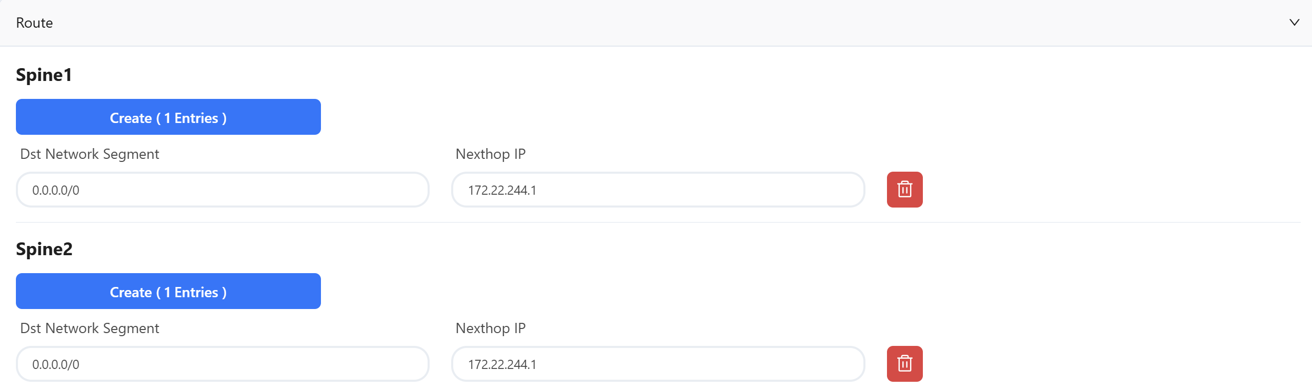
Section titled “Egress Router”Click [Create], select the interface ID of the Spine device’s uplink interface, and configure the IP address as per the service plan.
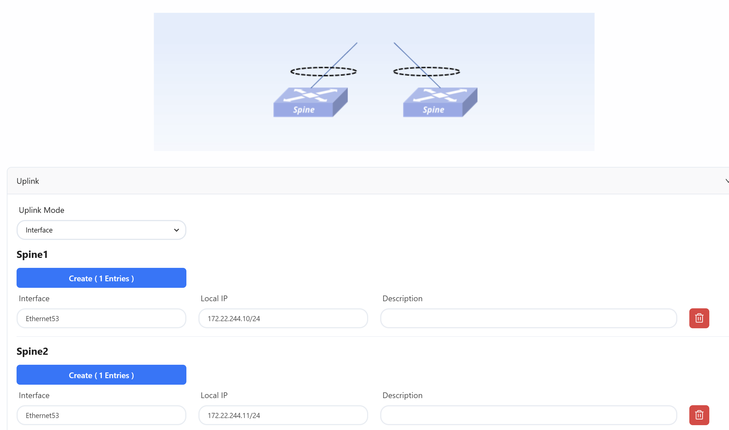
To ensure normal network operation, a default route typically needs to be configured, with the next hop IP set as the peer IP address of the Spine uplink interface.
Device
Section titled “Device”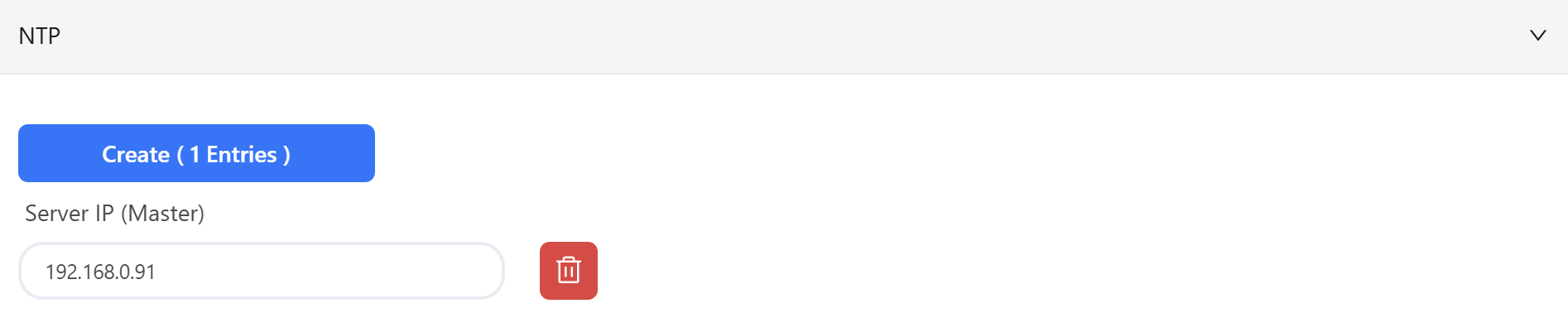
NTP: Configure the NTP server IP address as the Controller’s address to provide a unified, accurate, and reliable time reference for the devices.
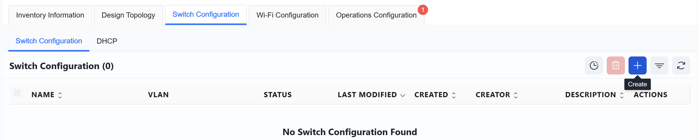
Switch Configuration
Section titled “Switch Configuration”Switch Configuration
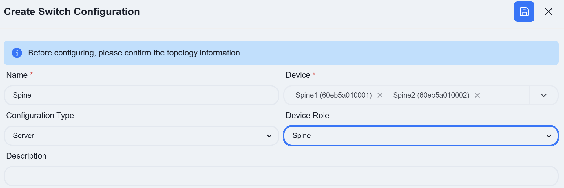
Section titled “Switch Configuration”Click [Create] on the right to set up the switch configuration.
Default Zone
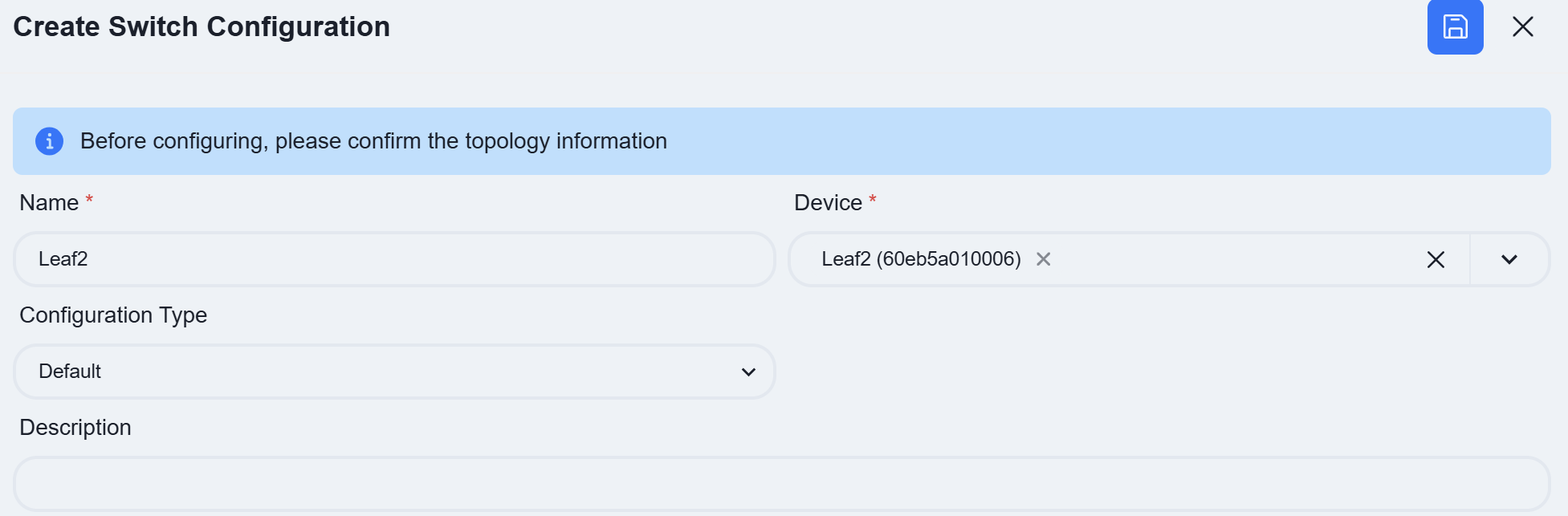
Section titled “Default Zone”Leaf1
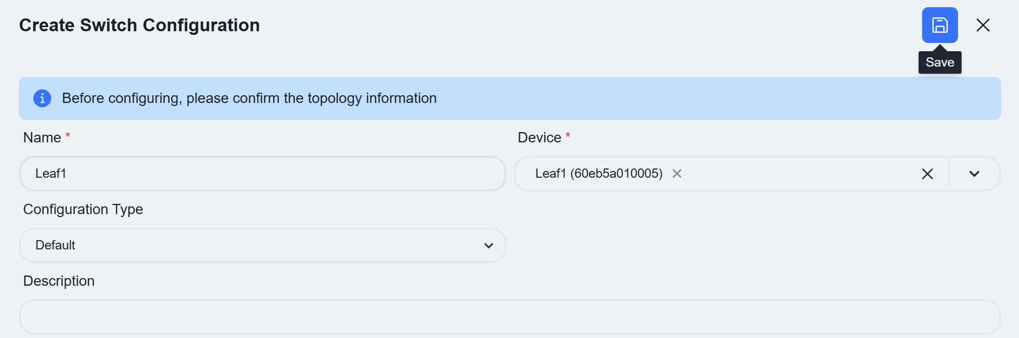
Name: User-defined
Device: Select the Access-1 device
Configuration Type:Select Default
| Procedure | Description |
|---|---|
| Step 1 | DHCP Relay Since the DHCP Server is deployed on the Spine and is not directly connected to the service devices on Leaf1, a DHCP relay needs to be configured. 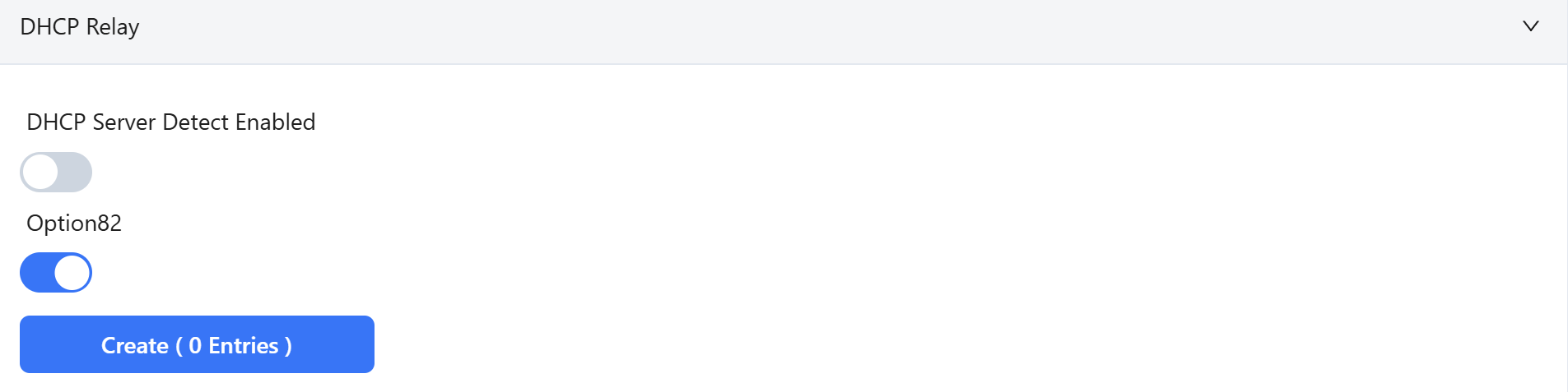 Click [Create], enter the DHCP server IP in the pop-up page, and then click [Add] after completion. 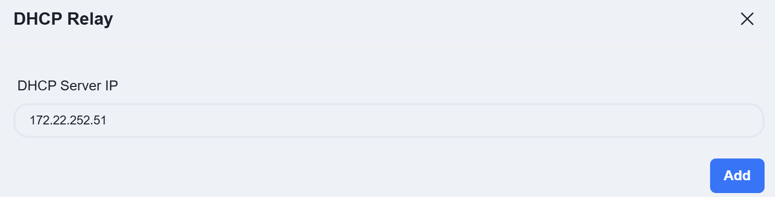 Since DHCP Servers are deployed on both Spine devices with DHCP Failover configured, two DHCP server IP addresses need to be entered. 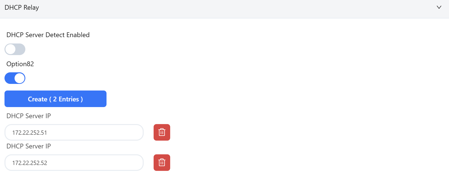 |
| Step 2 | Business VLAN Deploy wireless service configuration on Leaf1 and set up the service gateway. Configure the AP management VLAN  Configure the Wireless Business VLAN  IP: Enter the service gateway address. Access/Trunk: Select the mode based on whether the interfaces send and receive frames with VLAN tags. * Trunk: Receives tagged frames. Typically configured for wireless service VLANs. |
- Access: Receives untagged frames. Typically configured for the AP management VLAN and wired service VLANs.
Members: Click the dropdown arrow to select the member interfaces for the VLAN on the device. | | Step 3 | POE
The access switch features PoE functionality, which can be directly enabled in the wired service configuration to supply power to PD devices.
Click [Create]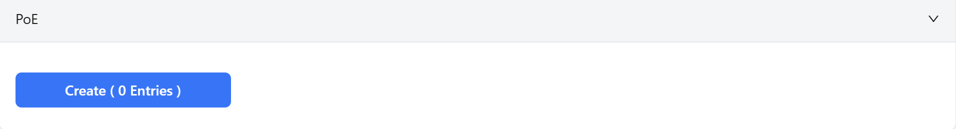
Select the interface where the PoE function is to be enabled and set the startup delay time.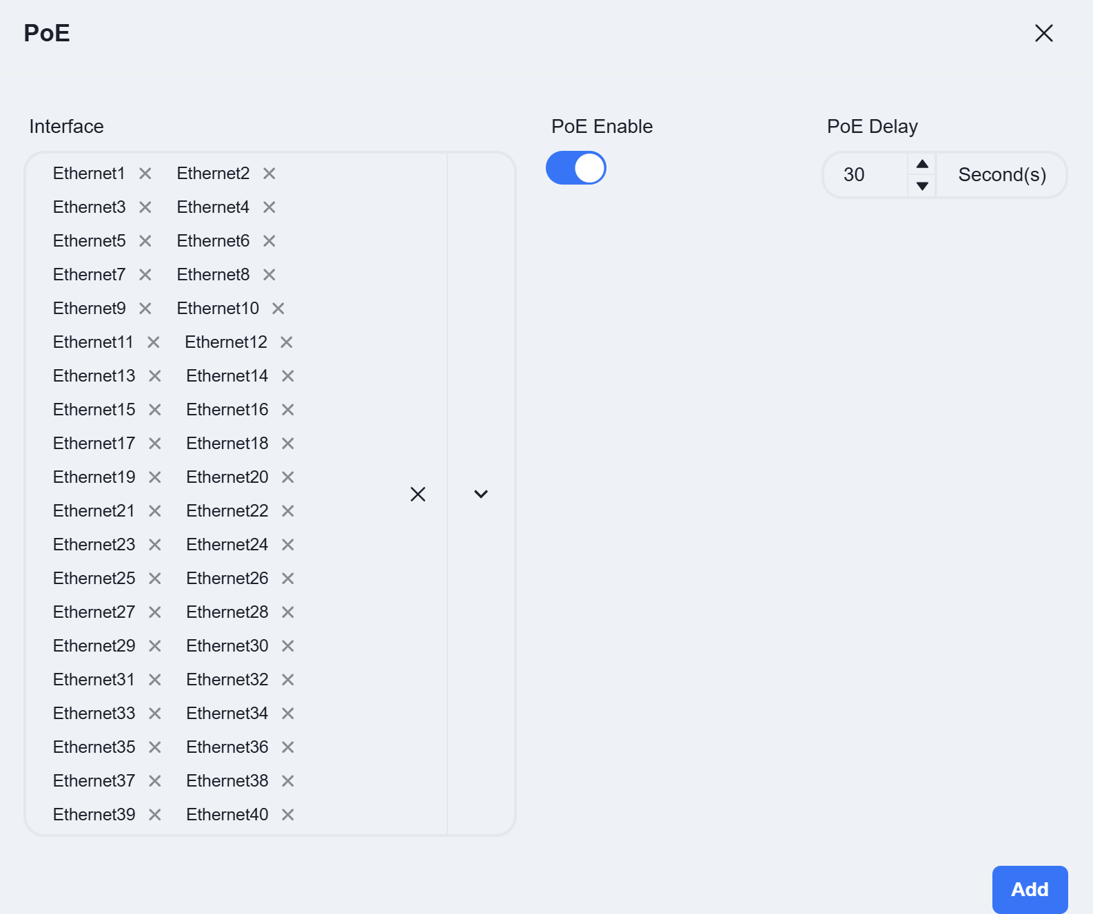
POE Delay: This refers to a brief, intentional time delay introduced at a PoE switch port between when it begins to supply power and when it actually delivers power to the Powered Device (PD). |
Once all configurations are completed, click [Save] in the top right corner to finish configuring Leaf1.
Leaf2
| Procedure | Description |
|---|---|
| Step 1 | DHCP Relay Same as Leaf1 |
| Step 2 | Business VLAN Deploy wired service configuration on Leaf2 and set up the service gateway.  |
| Step 3 | Wired Clients Information Collection Interfaces with this feature enabled will report information about the connected wired terminals to the controller. 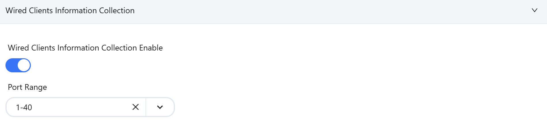 |
Server Zone
Section titled “Server Zone”Leaf
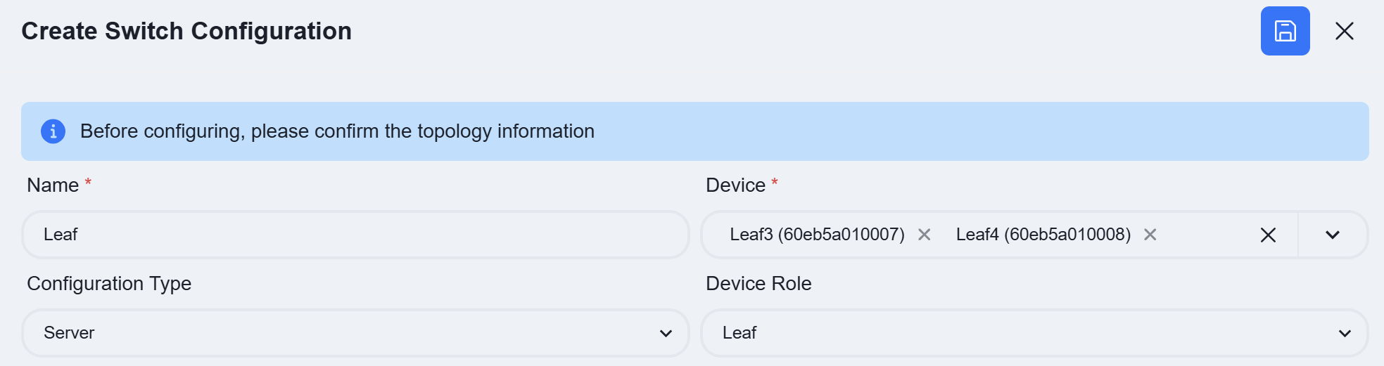
| Procedure | Description |
|---|---|
| Step 1 | Link Aggregation Click [Create] 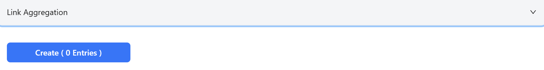 Enter the Link Aggregation ID and Members in the pop-up view. 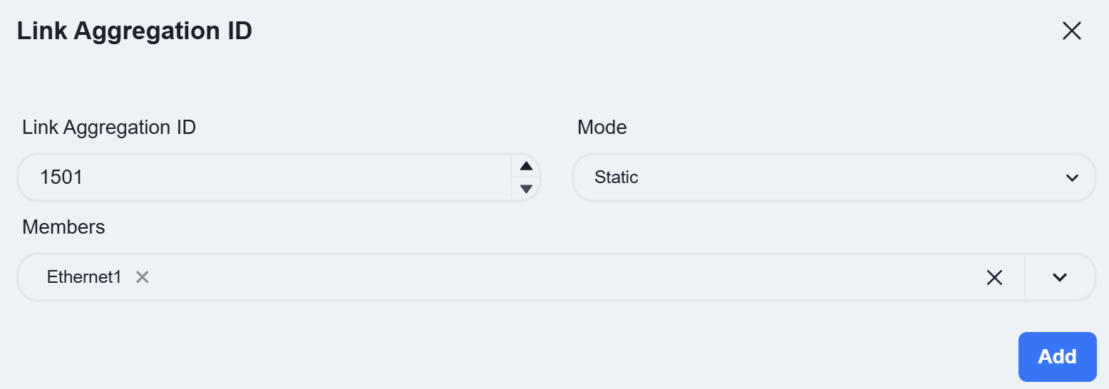 Link Aggregation ID: Users can create an ID within the range of 1501—2000 as needed. |
| Mode: Static/LACP, select whether the link aggregation mode is static or LACP dynamic negotiation. | |
| Members: Select the member interfaces connected to this service server. | |
| Step 2 | Business VLAN Click [Create] 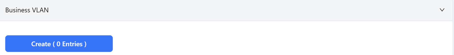 Fill in the relevant information in the pop-up view. 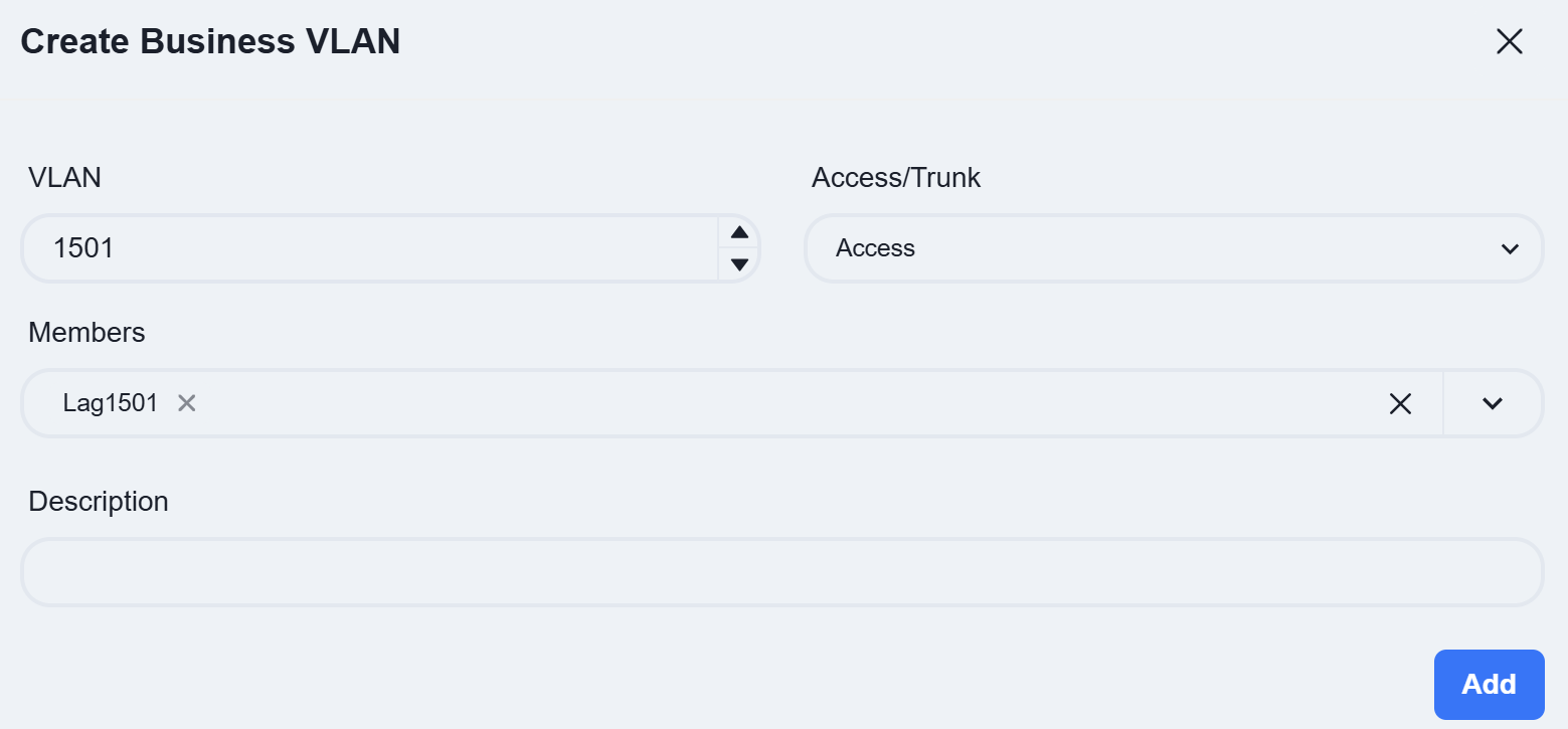 VLAN: Users can enter a VLAN ID between 2 and 4050 according to the service plan. |
| Members: Only LAG interfaces configured in link aggregation can be selected as member interfaces. |
Click [Save] after completing all configurations.
Spine
| Procedure | Description |
|---|---|
| Step 1 | DHCP Relay**** Since the DHCP service is deployed on the Spine, no relay configuration is required on the Spine. |
| ** Step 2** | Business VLAN Click [Create] 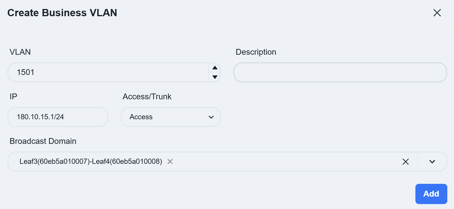 ** VLAN:** Corresponds to the service VLAN of the server area Leaf switch.** IP:** Enter the gateway IP address of the service VLAN as planned.** Broadcast Domain:** Select the Leaf switch corresponding to the VLAN. |
Click [Save] after completing all configurations.
The controller allows users to configure the DHCP Server function on Spine devices.
After entering the site, click [Configuration]-[Switch Configuration]-[DHCP] to access the DHCP Server configuration interface. Then, click the [+] button on the page to create a new configuration:
Create AP Management Address Pool
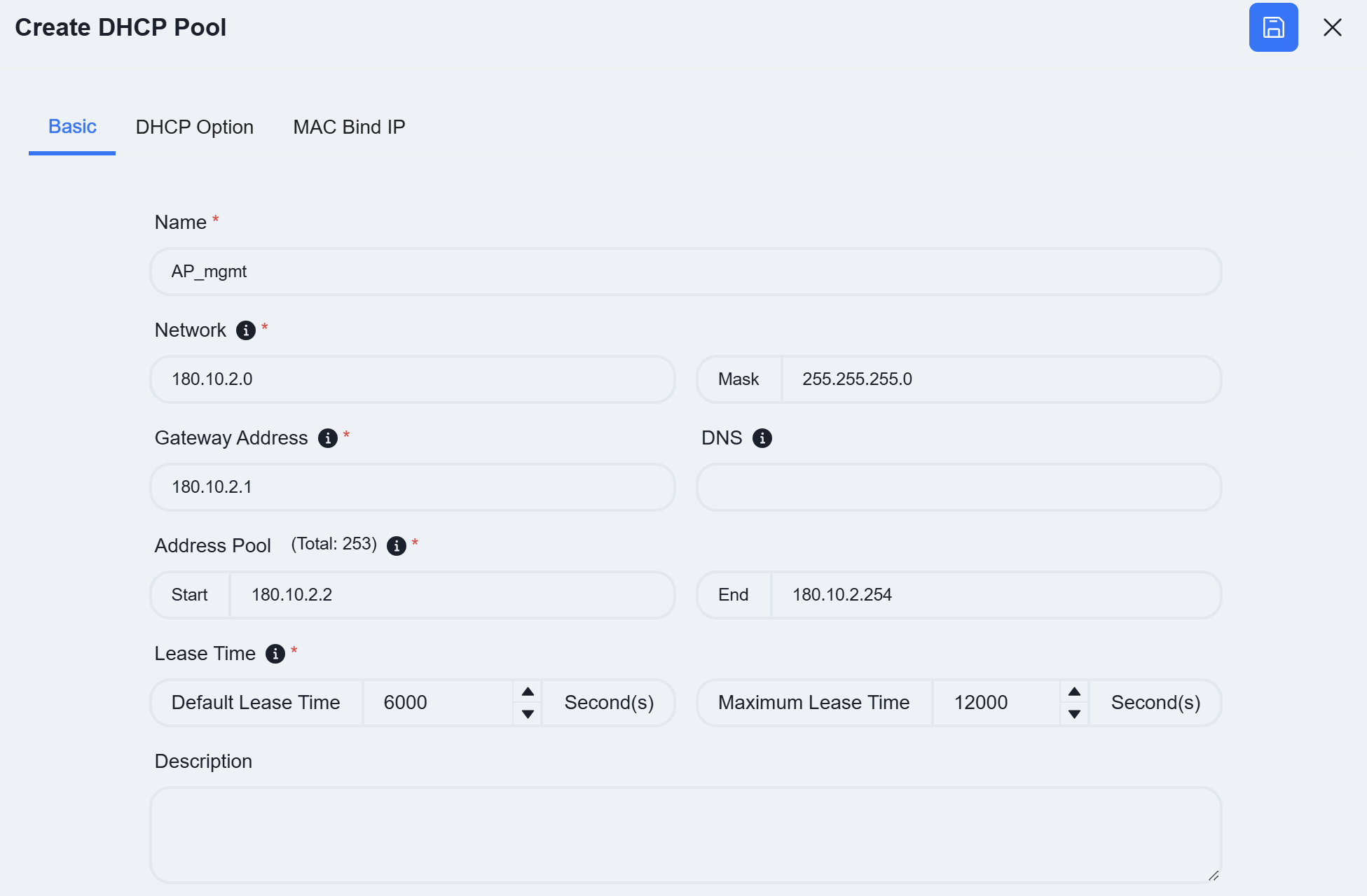 ** Name:** User defined.** Network:** Specify the network segment where the IP address assigned by the DHCP server to the DHCP client is located.** Gateway Address:** Specify the gateway address assigned by the DHCP server to the DHCP client.** DNS:** Specify the DNS server address.** Address Pool:** Specify the address range allocated by the DHCP server to DHCP clients.** Lease Time:** Specify the IP address lease time.
Click on [DHCP Option] and fill in the relevant information.
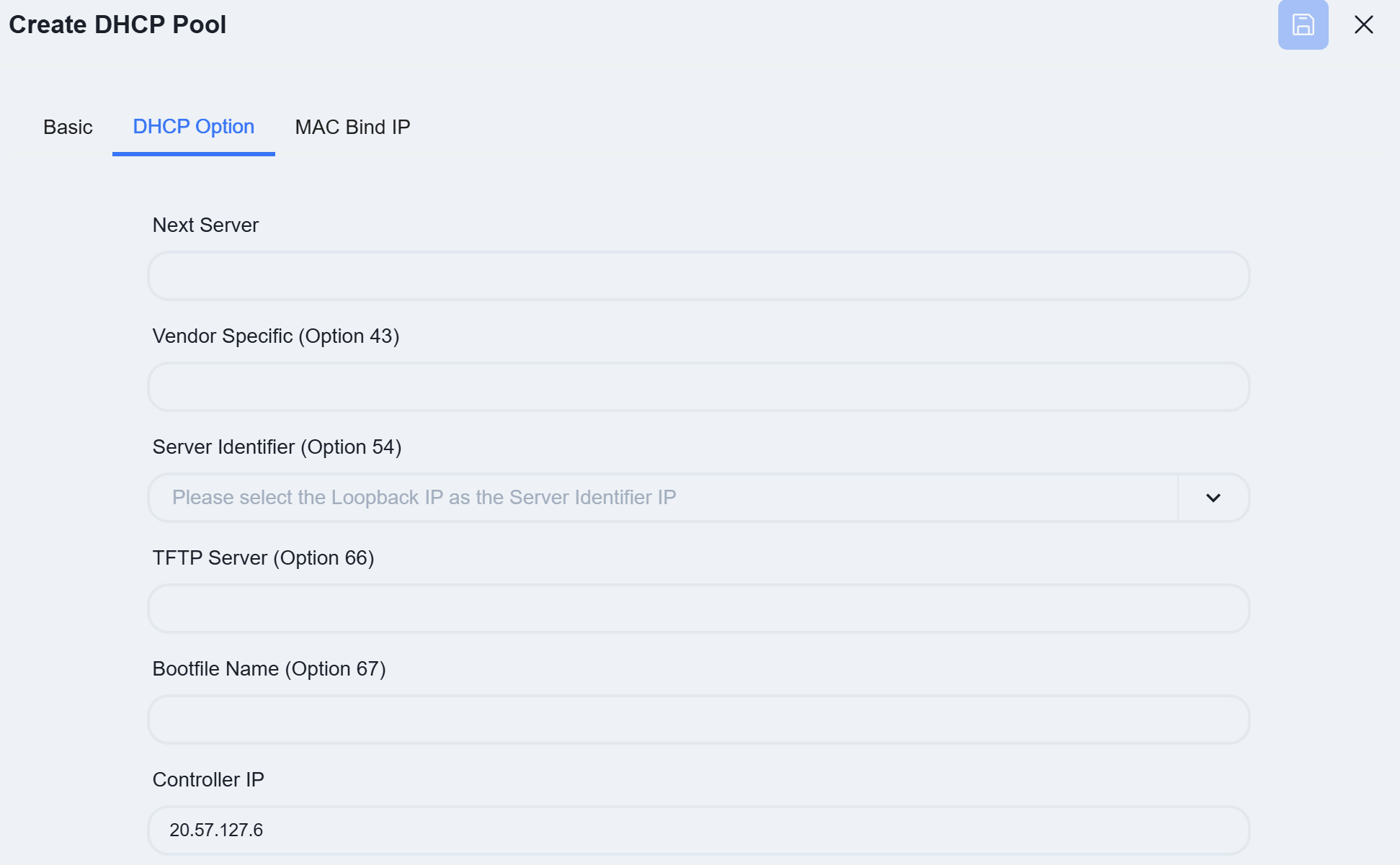 ** Controller IP **: DHCP options specifically designed for wireless AP discovery controllers, fill in the controller IP address.
The controller supports configuring MAC binding IP function, which users can fill in as needed.
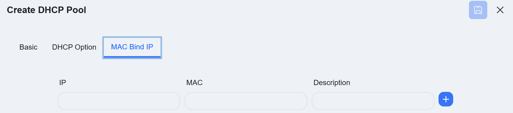
Click [Save] after completing all configurations.
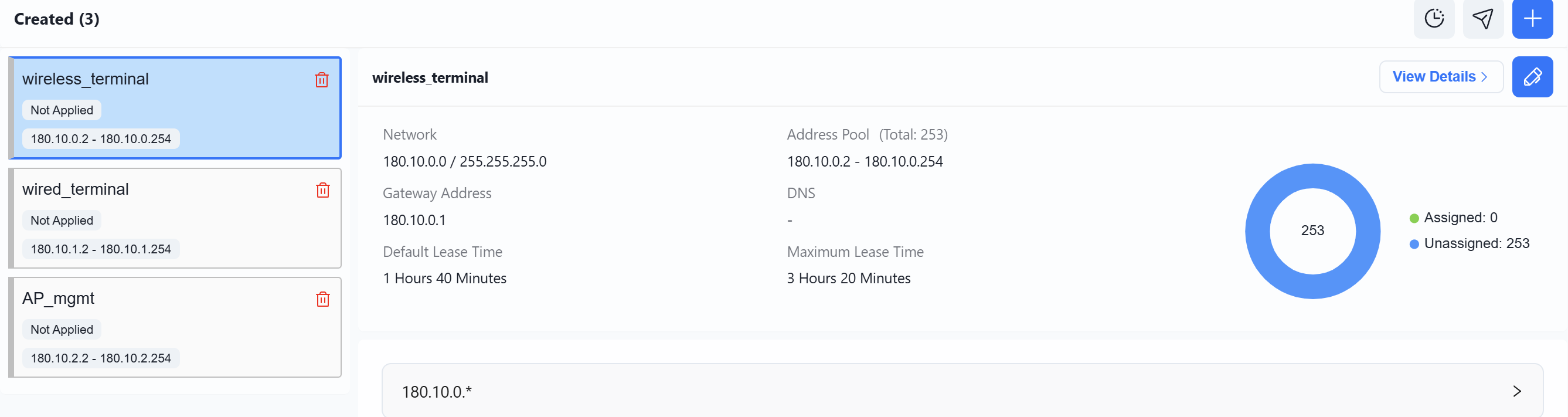
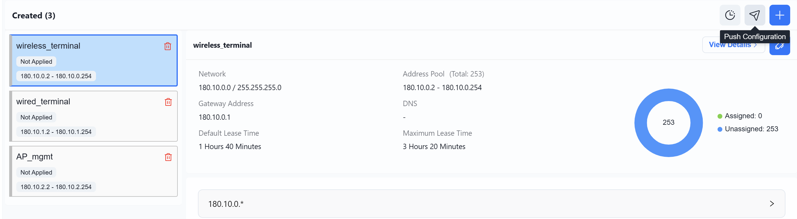
Follow the steps above to sequentially create the DHCP configurations for wireless terminals and wired terminals. Once all configurations are completed, the DHCP view will appear as shown below.
Wi-Fi Configuration
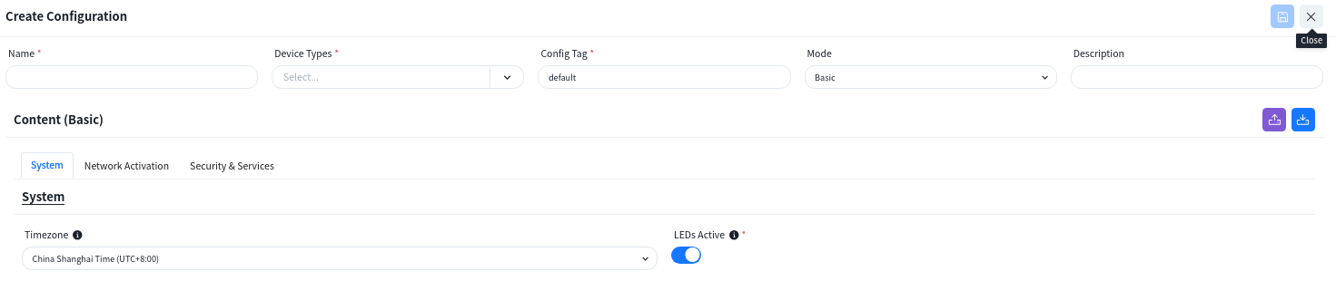
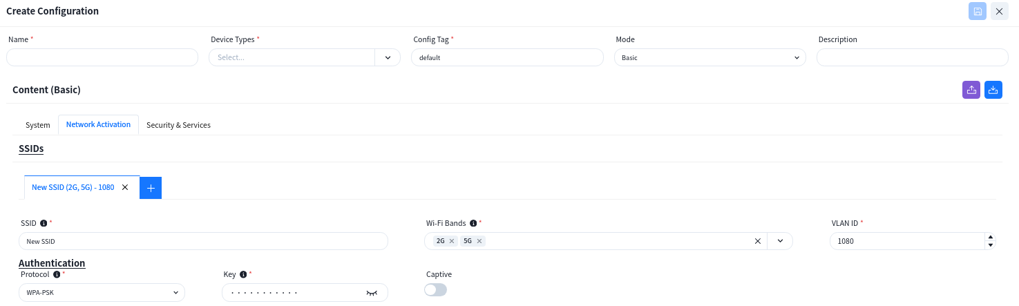
Section titled “Wi-Fi Configuration”Click [Wi-Fi Configuration] - [+] to configure the necessary basic information for the wireless AP, e.g. SSID settings, security policy. The controller can automatically generate the corresponding
The controller supports the configuration of different wireless service configurations, and after the AP goes online, it will determine which configuration should be issued to the AP based on the [Config Tag] attributes of the configuration.
When the AP is one that has an extended wired interface and is capable of accessing terminals by wired means, such as a panel AP, the user can configure the access method for wired terminals through the configuration in LANs.
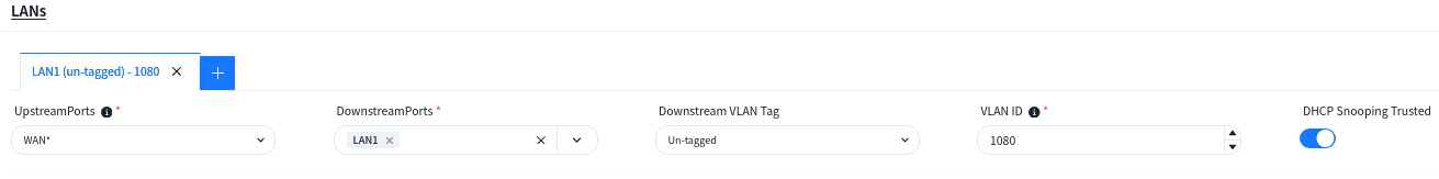 ** UpstreamPorts:** Specify the up-link interfaces for wired terminal to access the network through AP, usually it is the interface for AP to connect to the switch, and keep the same with [UpstreamPorts] in [SSID]—[Advanced] Settings, the default is: WAN*.
DownstreamPorts: Interfaces for wired terminal access.
Downstream VLAN Tag: Whether the wired terminal carries VLAN Tag.
VLAN ID: The AP receives messages from wired terminals that add this VLAN TAG to identify.
DHCP Snooping Trusted: DHCP Snooping Trusted interface, if the wired terminal needs to obtain IP address through DHCP service, this switch needs to be on.
Configuration Release
Section titled “Configuration Release”Switch
Section titled “Switch”Switches support both in-band and out-of-band management methods. Operation and maintenance personnel can flexibly choose based on current network conditions. For devices in the factory default state, whenever either the management port or service port is in an “Up” state, they will actively initiate a DHCP request to obtain a temporary management IP address and the IP address of the cloud-based controller from the DHCP server. They will then connect to the controller to retrieve configuration information.
Once all switches are successfully connected to the controller, click [Topology Consistency Verification] on the upper right side of the [Design Topology] view to confirm whether the generated topology matches the planned topology. After verification, the controller can deploy configurations to the switches.
Push Basic Network Configuration
Section titled “Push Basic Network Configuration”Click [Configuration] - [Design Topology] - [Basic Network] - [Push Configuration] to issue the basic configuration for all devices.
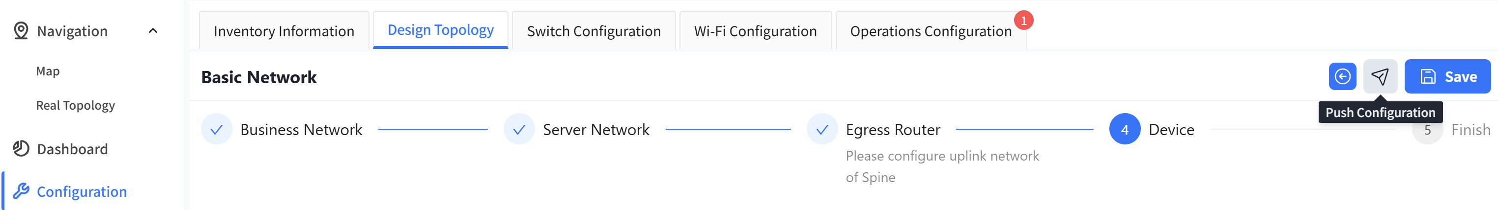
By default, the controller will select all switches. Click the [Next] - [Start] button to start issuing basic network configurations for the switches.
Push Switch Configuration
Section titled “Push Switch Configuration”Switch Configuration
On the [Configuration]-[Switch Configuration] view, select the configuration to be deployed and click the [Push Configuration] button.
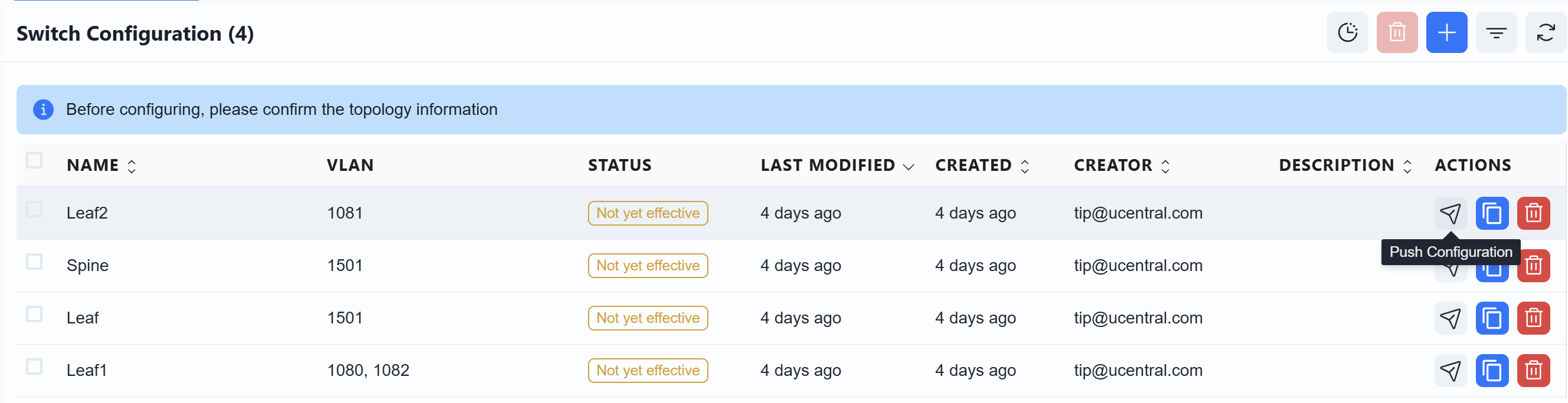
In the pop-up window, click [Next]-[Start] to deploy the switch configuration to the switch.
DHCP
On the [Configuration] - [Switch Configuration] - [DHCP] interface, select the configuration to be deployed and click the [Push Configuration] button to deliver the configuration.
The AP does not need to manually issue the configuration. After the configuration of the device is issued and takes effect, the PoE power supply function of the switch is turned on, and the AP can power on and work. When the AP connects to the controller with the information obtained through the DHCP service, the controller will automatically send the configuration to the corresponding AP based on the comparison between the TAG identification stored in the AP inventory and the TAG identification in the planning configuration.