
Traditional Layer 2 Networking Scenarios
The traditional Layer 2 network solution is based on the classic Spine-Leaf architecture, enabling visualised, automated deployment and management through a centralised controller.This solution adheres to the design principles of network stratification and separation of responsibilities, providing a stable, efficient, and easily maintainable standardised foundational network platform for environments such as campuses and data centres. It combines a reliable architecture proven over decades with modern centralised management capabilities, ensuring non-blocking, low-latency forwarding of service traffic within Layer 2 domains while achieving centralised and highly available Layer 3 gateway functionality.
Centralised Policy Management and Automated Deployment
Through a unified controller, the solution abstracts complex VLAN, port, Spanning Tree, and gateway configurations into intuitive policy templates. Operations personnel can deploy configurations across the entire network in bulk and with precision via a graphical interface, eliminating the need for individual device logins. This fundamentally prevents misconfigurations and inconsistencies that may arise from manual command-line operations, reducing network deployment time from days to hours.
Intelligent Unified Operations Management and Proactive Insights
At the deployment and management level, this solution achieves centralised policy distribution and device management through a unified controller. Beyond this, the controller possesses robust real-time monitoring and intelligent analysis capabilities. It continuously collects operational status and performance metrics from all network devices, intelligently calculates health scores for each device based on multi-dimensional data, and provides comprehensive logging with precise real-time alerts. This mechanism significantly simplifies network operations, enabling administrators to proactively identify potential risks, rapidly pinpoint issues, and resolve them, thereby comprehensively enhancing operational efficiency and network reliability.
Ultimate Reliability and High Performance in Classic Architecture
Employing a Spine-Leaf classic network topology, the Leaf layer functions as pure Layer 2 equipment, dedicated to high-speed access and local switching. The Spine layer acts as Layer 3 gateways and policy enforcement points, enabling centralised, efficient routing of cross-subnet traffic. This clear division of responsibilities renders network behaviour entirely predictable, providing upper-layer services with consistently low-latency, high-bandwidth stable connections.
Scheme Design
Section titled “Scheme Design”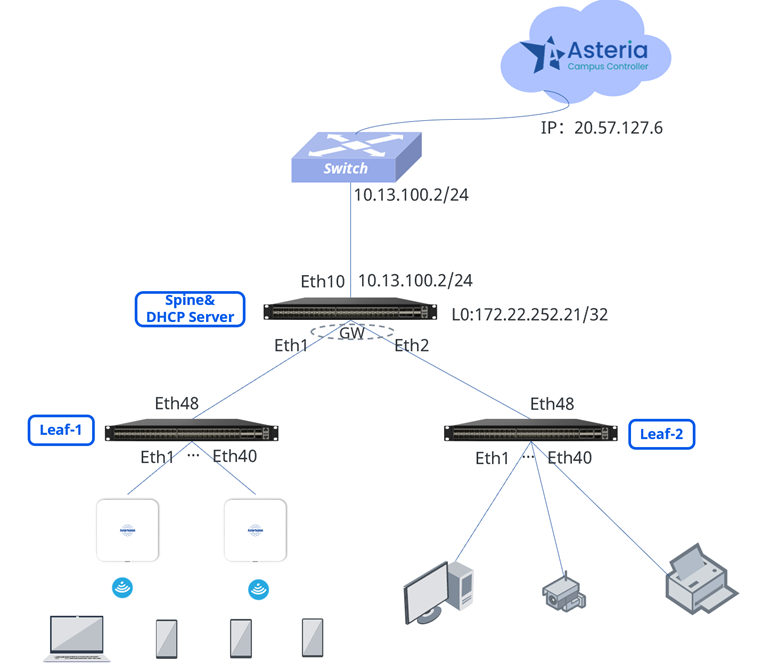
Network Architecture:
Traditional Layer 2 gateways are deployed on Spine devices, with Leaf devices operating purely as Layer 2 switches. This approach is suitable for wired networks in campus server zones or traditional access/aggregation networks in small-to-medium campuses. It provides classic Layer 2 forwarding to meet requirements for traditional Layer 2 architectures.
DHCP Deployment:
DHCP is centrally deployed on Spine devices.
Controller Deployment:
Controllers are deployed in the cloud, enabling unified management through a graphical interface. This facilitates centralised policy distribution, configuration management, and status monitoring, significantly enhancing operational efficiency. Particularly for device configuration and deployment, this approach substantially reduces workload.Service Planning:
Service Plan:
| Service Type | IP Segment | Gateway | Service VLAN | SSID |
|---|---|---|---|---|
| Wireless Service | 180.10.0.0/18 | 180.10.0.1/18 | 1080 | New SSID |
| Wired Service& | ||||
| AP Management | 180.10.18.0/24 | 180.10.18.1/24 | 1888 | - |
Device Import
Section titled “Device Import”Administrators can create or import devices in bulk to specified sites/organizations. When an added inventory device connects to the controller and comes online, the controller will automatically assign it to the designated organization/site based on its MAC address.
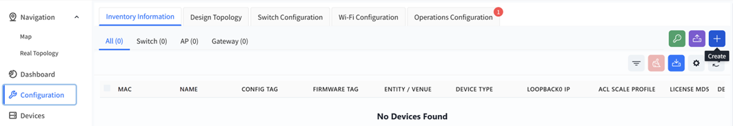
Add Devices One by One.
Section titled “Add Devices One by One.”Click [Configuration] - [Inventory Information] - [+] to create an inventory device.
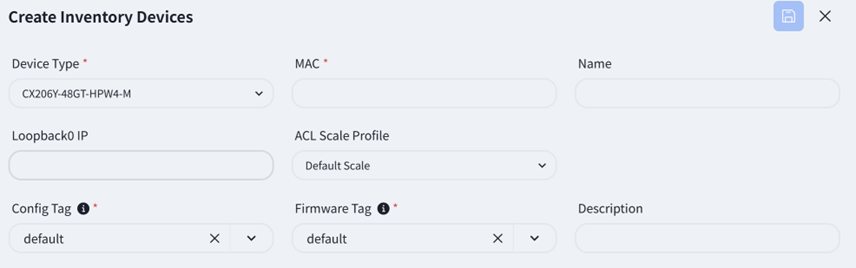
Fill in the relevant information as prompted on the page
Import via Excel
Section titled “Import via Excel”Click [Upload Devices]
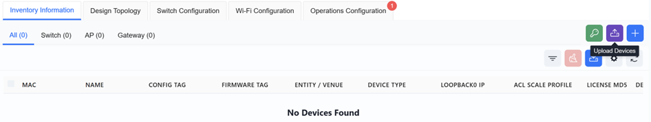
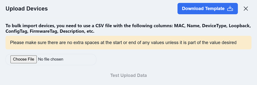
Click [Download Template] and enter the information for the devices to be added to the inventory according to the template’s specifications.
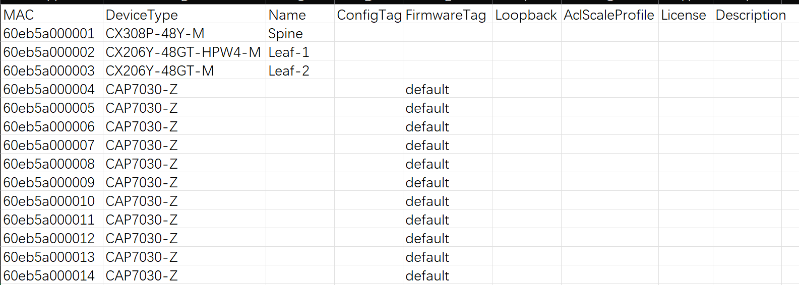
MAC: The device’s MAC address. This information is typically found on the device’s label.
Device Type: The device model.
Name: The device hostname. By default, it is the device’s MAC address.
ConfigTag: After an AP connects to the controller, it will automatically pull the configuration file corresponding to this tag. By default, the tag value is default.
FirmwareTag: When performing firmware upgrades, devices requiring an upgrade can be filtered based on their firmware tag type. By default, the tag value is default.
Loopback: The device’s loopback address. For all devices operating at Layer 3, this address serves as the device’s in-band management address.
AclScaleProfile: Optional values are default or large-scale. By default, the value is default.
License: The AP’s license file. For bulk imports, you can either enter the JSON-formatted license file content directly in the Excel sheet, or add all devices to inventory first and then import the license files in bulk afterward.
Description: Descriptive information about the device.
Click [Choose File] to upload the completed template, then click [Test Upload Data]. The controller will automatically check if the uploaded data complies with the specifications and display the results in the test report.
Once completed, users can view the created devices in the [Inventory Information] view.
Service Configuration
Section titled “Service Configuration”Design Topology
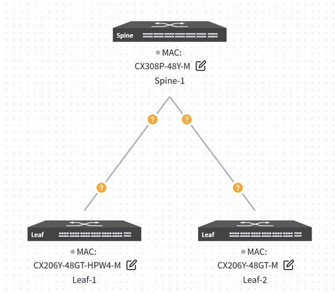
Section titled “Design Topology”Navigate to the [Configuration] page in the controller’s navigation bar. Click [Plan Topology], select the [Traditional L2 network], enter the model and quantity of Spine and Leaf devices, then click [Finish] to finalise the network topology pre-planning. The controller will generate a recommended network topology based on pre-planned typical network topologies.

The generated topology is displayed as follows:
Users may click the [Edit] button on the device side, select the device from inventory to apply to the current topology in the right-hand slide-out panel, then choose the interconnect interface.
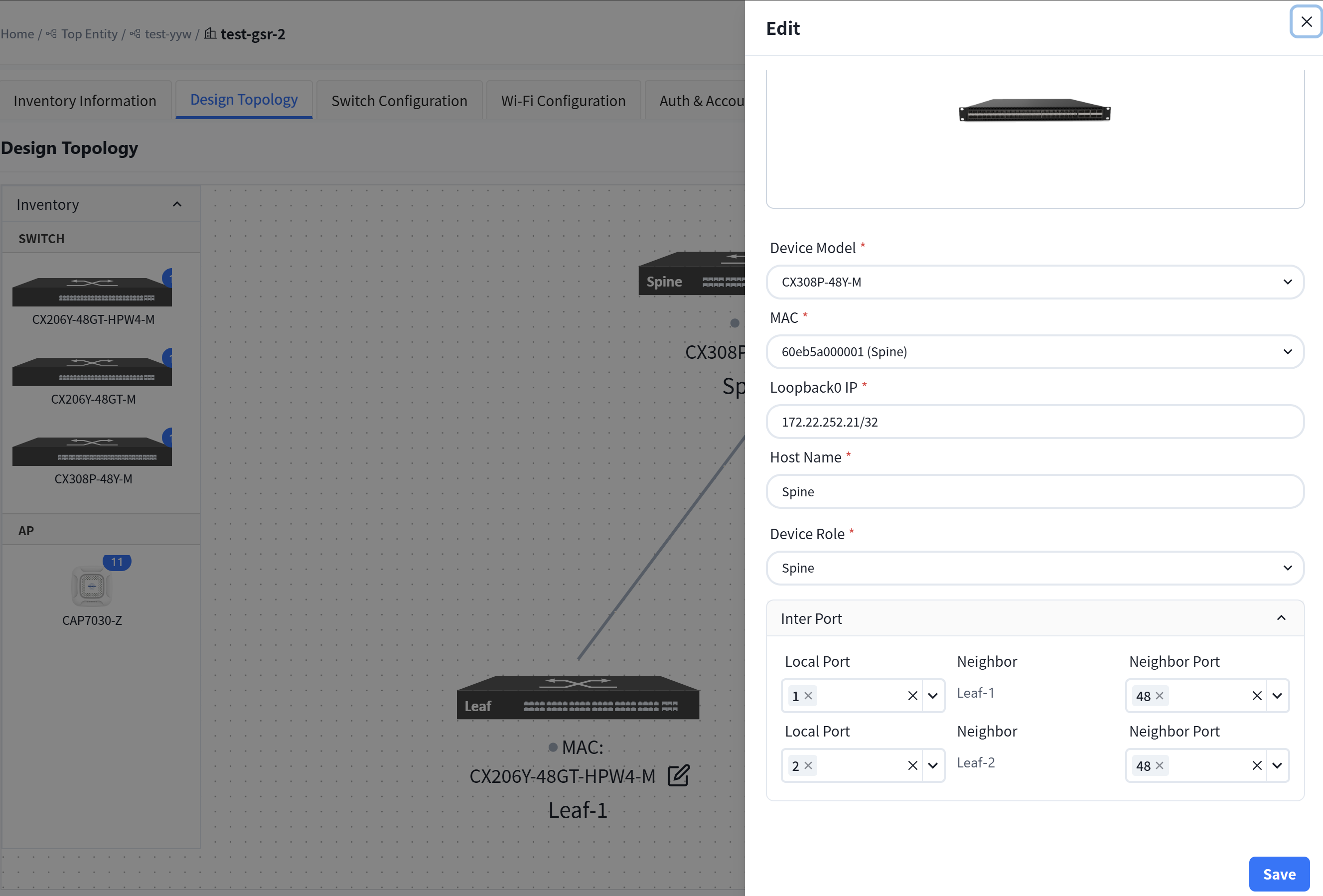
MAC: Uniquely select a device via its MAC address.
Loopback0 IP: Configure the IP address for the device’s Loopback0 interface, which will be used for in-band management of the device.
Hostname: Configure the hostname of the device.
Device role: Assign the device role as Spine or Leaf.
Inter Port:
Local Port: The interface on the current device.
Neighbor: Select the peer device connected to the local interface.
Neighbor Port: The interface on the peer device interconnected with the current device’s local interface.
Upon completing all configurations, click [Save] in the upper right corner of the page, then select [Confirm] in the pop-up window.
Basic Network
Section titled “Basic Network”Click the top right corner [Basic Network]

In traditional Layer 2 network scenarios, the in-band management method for Leaf devices involves creating a VLANif interface as the in-band management interface to connect to the controller. On this page, administrators can specify a VLAN ID as the in-band management VLAN, configure the management IP address range and the in-band management gateway address (which will be configured on the Spine device), select the VLAN member interfaces, and set the mode to access when joining the VLAN.
The controller will allocate a management IP address to each Leaf switch from the specified address range, displaying the allocation results in the table below:
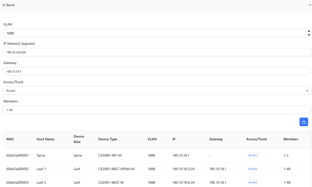
Access/Trunk: Select this mode based on whether the interface transmits and receives VLAN-tagged packets.
Access: Accepts packets without VLAN tags. Typically configured as the management VLAN for switches or APs, or as a wired service VLAN.
Trunk: Accepts VLAN-tagged packets, typically configured for wireless service VLANs.
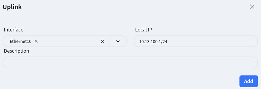
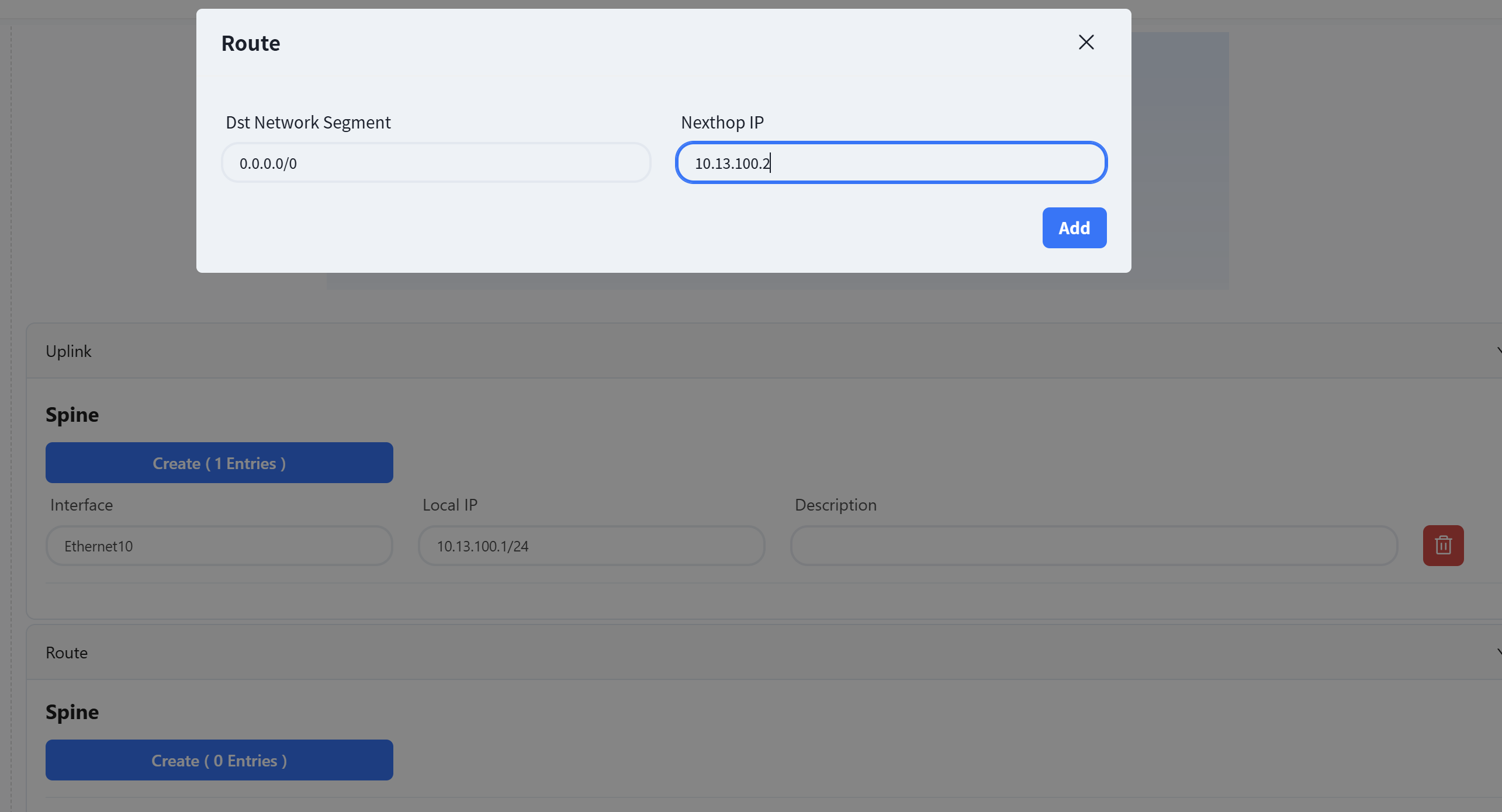
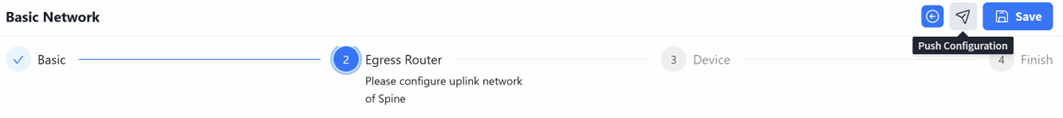
Egress Router
Section titled “Egress Router”Select the interface ID for the uplink interface on the Spine device and configure its IP address.
In traditional Layer 2 scenarios, the Spine only supports connecting to external networks via static route configuration. To ensure normal network operation, a default route is typically required.
Device
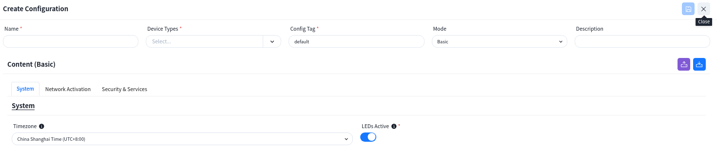
Section titled “Device”Configure device management related information:
TimeZone: Configure the system time zone.
NTP: Configure NTP Server.
SNMP: Configure SNMP community.
Syslog: Configure syslog server IP address.
TACACS+: Configure TACACS server IP address.
Device ACL: Configure ACL rules restricting SSH, SNMP, TELNET connections to device.
After completing all configurations, click [Save]
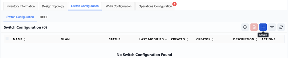
Switch Configuration
Section titled “Switch Configuration”Switch Configuration
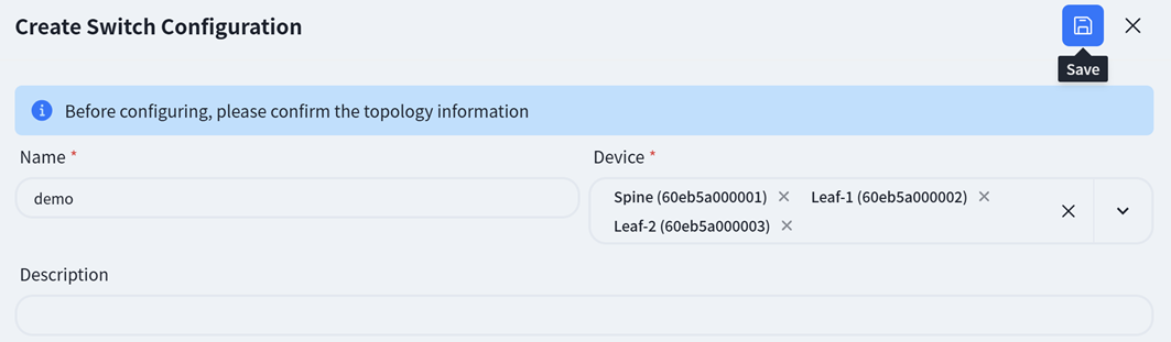
Section titled “Switch Configuration”Click [Create] on the right to set up the switch configuration.
Unlike full three-layer networks, in traditional two-layer networks, the service network is deployed on Spine devices. Therefore, when selecting devices, it is also necessary to add devices of the Spine type.
Spine
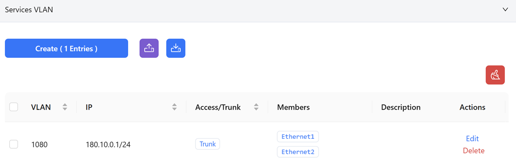
Creating a Service VLAN:
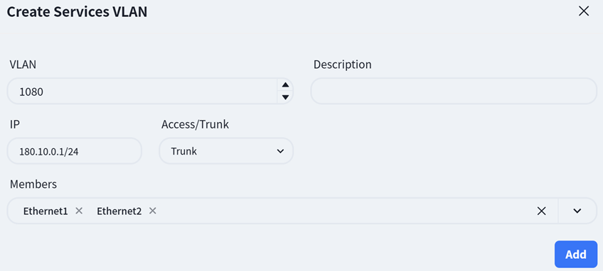
VLAN: Create a service VLAN
IP: Configure the address as the gateway for this service VLAN
Access/Trunk: Select this mode based on whether the interface transmits or receives VLAN-tagged packets
Access: Accepts packets without VLAN tags, typically configured for AP management VLANs or wired service VLANs
Trunk: Accepts VLAN-tagged packets, typically configured for wireless service VLANs
Members: Click the dropdown arrow and select the member interfaces for the VLAN on the Spine device. Typically, this includes all interfaces connected to Leaf switches.
Leaf
Leaf switches operate in pure Layer 2 configuration. On this interface, only the VLAN ID and member interfaces need to be specified; all other configurations are generated by the controller.

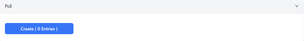
POE
The access switch features PoE functionality, which can be directly enabled in the wired service configuration to supply power to PD devices.
Click [Create]
Select the interface where the PoE function is to be enabled and set the startup delay time.
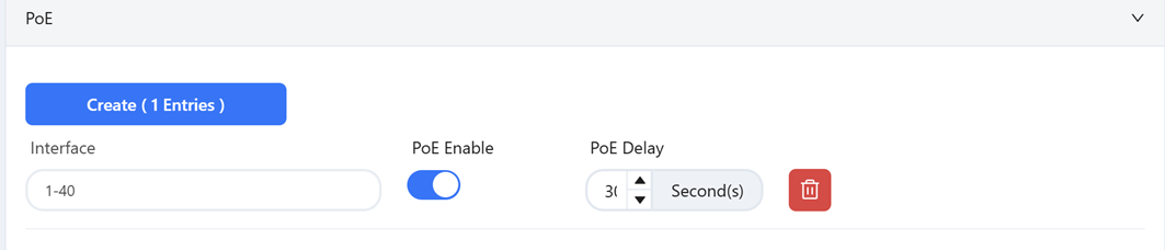
POE Delay: This refers to a brief, intentional time delay introduced at a PoE switch port between when it begins to supply power and when it actually delivers power to the Powered Device (PD).
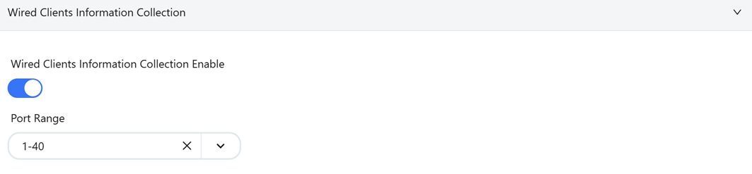
Wired Clients Information Collection
Interfaces with this feature enabled will report information about the connected wired terminals to the controller.
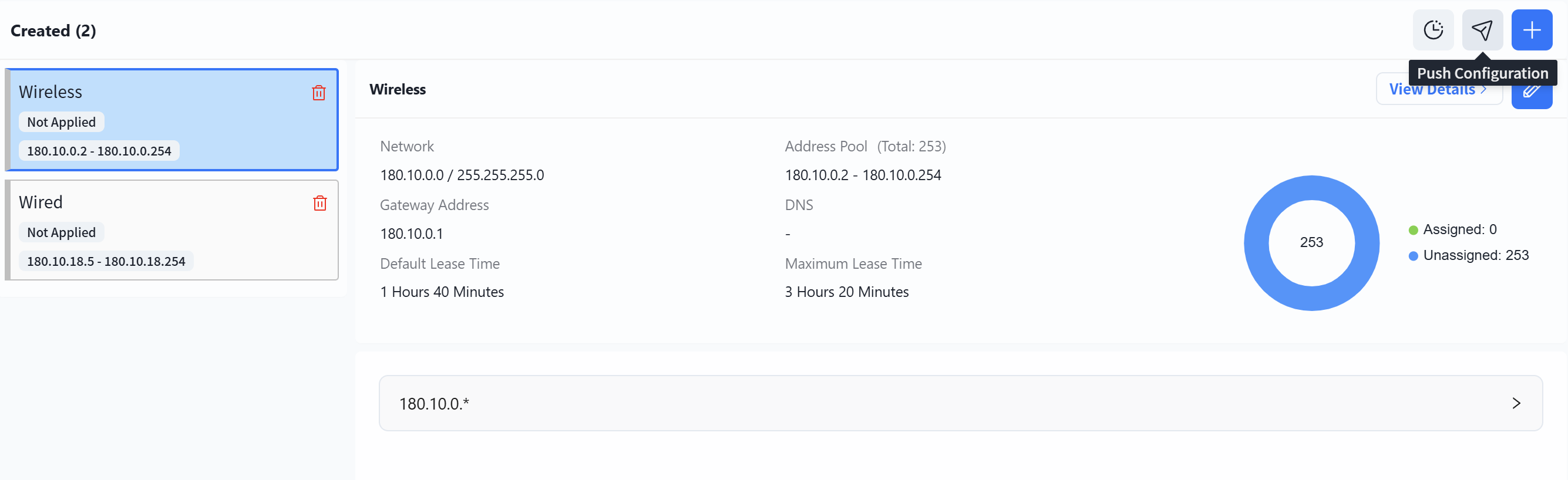
The controller allows users to configure the DHCP Server function on Spine devices.
After entering the site, click [Configuration] - [Switch Configuration] - [DHCP] to access the DHCP Server configuration interface. Then, click the [+] button on the page to create a new configuration:
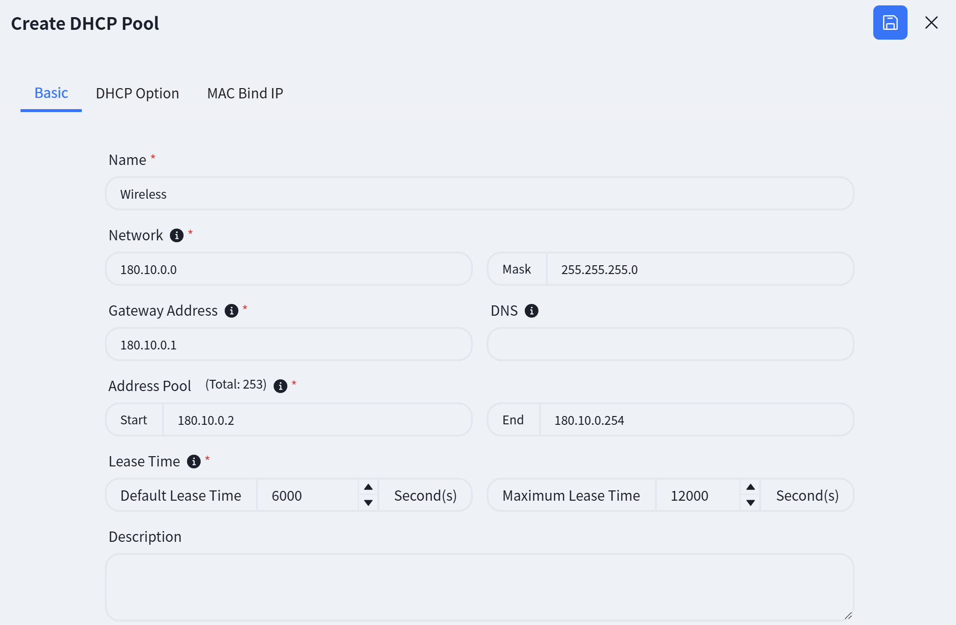
Create Wired Services and AP Management Address Pool
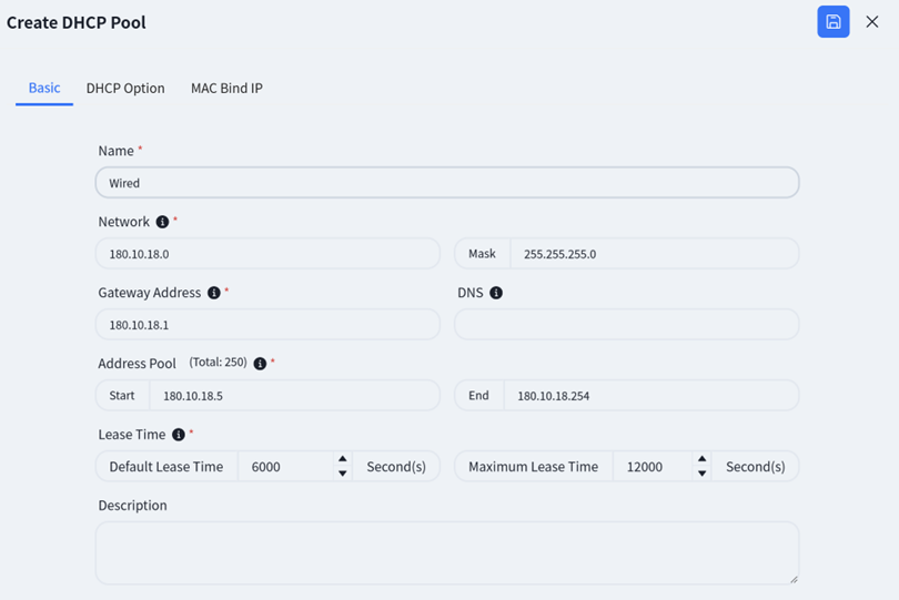
Name: User defined.
Network: Specify the network segment where the IP address assigned by the DHCP server to the DHCP client is located.
Gateway Address: Specify the gateway address assigned by the DHCP server to the DHCP client.
DNS: Specify the DNS server address.
Address Pool: Specify the address range allocated by the DHCP server to DHCP clients.
Lease Time: Specify the IP address lease time.
Click on [DHCP Option] and fill in the relevant information.
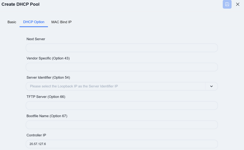
Controller IP: DHCP options specifically designed for wireless AP discovery controllers, fill in the controller IP address.
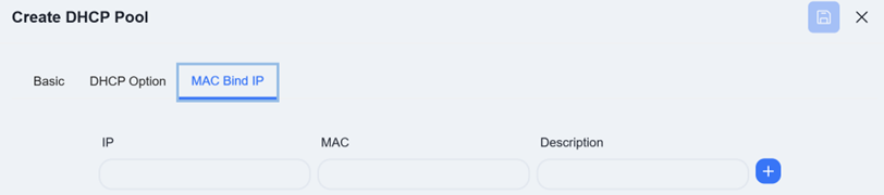
The controller supports configuring MAC binding IP function, which users can fill in as needed.
Create Wireless Services Address Pool
After completing all configurations, click [Save]
Wi-Fi Configuration
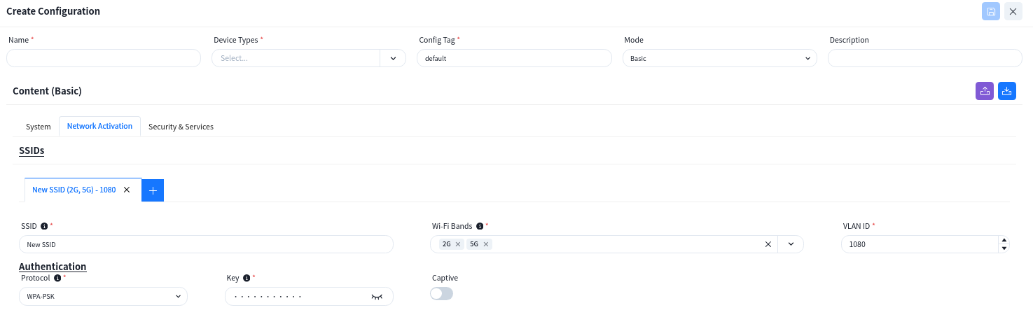
Section titled “Wi-Fi Configuration”Click [Wi-Fi Configuration] - [+] to configure the necessary basic information for the wireless AP, e.g. SSID settings, security policy. The controller can automatically generate the corresponding
The controller supports the configuration of different wireless service configurations, and after the AP goes online, it will determine which configuration should be issued to the AP based on the [Config Tag] attributes of the configuration.
LAN(Optional)
Section titled “LAN(Optional)”When the AP is one that has an extended wired interface and is capable of accessing terminals by wired means, such as a panel AP, the user can configure the access method for wired terminals through the configuration in LANs.
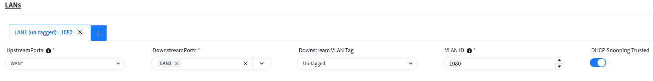
UpstreamPorts: Specify the up-link interfaces for wired terminal to access the network through AP, usually it is the interface for AP to connect to the switch, and keep the same with [UpstreamPorts] in [SSID] – [Advanced] Settings, the default is: WAN*.
DownstreamPorts: Interfaces for wired terminal access.
Downstream VLAN Tag: Whether the wired terminal carries VLAN Tag.
VLAN ID: The AP receives messages from wired terminals that add this VLAN TAG to identify.
DHCP Snooping Trusted: DHCP Snooping Trusted interface, if the wired terminal needs to obtain IP address through DHCP service, this switch needs to be on.
Configuration Release
Section titled “Configuration Release”Switch
Section titled “Switch”Switches support both in-band and out-of-band management methods. Operation and maintenance personnel can flexibly choose based on current network conditions. For devices in the factory default state, whenever either the management port or service port is in an “Up” state, they will actively initiate a DHCP request to obtain a temporary management IP address and the IP address of the cloud-based controller from the DHCP server. They will then connect to the controller to retrieve configuration information.
Once all switches are successfully connected to the controller, click [Topology Consistency Verification] on the upper right side of the [Design Topology] view to confirm whether the generated topology matches the planned topology. After verification, the controller can deploy configurations to the switches.
Push Basic Network Configuration
Section titled “Push Basic Network Configuration”Click [Configuration] - [Design Topology] - [Basic Network] - [Push Configuration] to issue the basic configuration for all devices.
By default, the controller will select all switches. Click the [Next] - [Start] button to start issuing basic network configurations for the switches.
Push Switch Configuration
Section titled “Push Switch Configuration”Switch Configuration
On the [Configuration]-[Switch Configuration] view, select the configuration to be deployed and click the [Push Configuration] button.
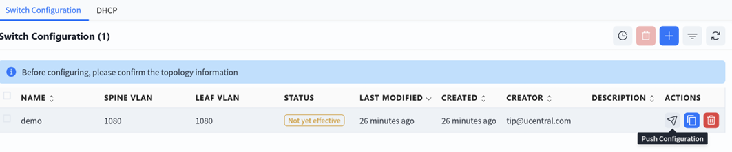
In the pop-up window, click [Next]-[Start] to deploy the switch configuration to the switch.
DHCP
On the [Configuration] - [Switch Configuration] - [DHCP] interface, select the configuration to be deployed and click the [Push Configuration] button to deliver the configuration.
The AP does not need to manually issue the configuration. After the configuration of the device is issued and takes effect, the PoE power supply function of the switch is turned on, and the AP can power on and work. When the AP connects to the controller with the information obtained through the DHCP service, the controller will automatically send the configuration to the corresponding AP based on the comparison between the TAG identification stored in the AP inventory and the TAG identification in the planning configuration.