
Open Cloud Connect Usage Guide
The Open Cloud Connect scenario fully unleashes the classic Layer 2 switching and Layer 3 routing capabilities in standalone mode. Its modular architecture provides flexible component combination options, allowing users to customize network functions based on actual business needs.
Visualized Centralized Management and Device-Level Flexible Configuration
This solution offers flexible and open network configuration capabilities. Through a centralized controller, operations staff can deliver configurations to switches via a graphical interface, significantly simplifying the deployment process. At the same time, the solution supports atomic-level, on-demand service configuration for individual devices. This process is independent of the network topology, offering high flexibility and scenario adaptability to precisely meet various business needs---from standardized deployments to highly customized requirements.
Intelligent and Unified Operations Management with Proactive Insights
In terms of deployment and management, this solution utilizes a unified controller for centralized policy distribution and device management. Beyond that, the controller boasts powerful real-time monitoring and intelligent analysis capabilities. It continuously collects operational status and performance metrics from across the network, intelligently calculates a health score for each device based on multi-dimensional data, and provides extensive logging and precise real-time alerts. This mechanism greatly simplifies network operations, enabling administrators to proactively identify potential risks, quickly locate issues, and resolve them---thereby comprehensively improving operational efficiency and network reliability.
Enhanced Network Services and Edge Autonomy
Furthermore, the system supports the direct deployment of DHCP servers on Leaf nodes, further enhancing the autonomy and deployment flexibility of network services. This effectively meets users’ address management requirements in diverse network environments.
Scheme Design
Section titled “Scheme Design”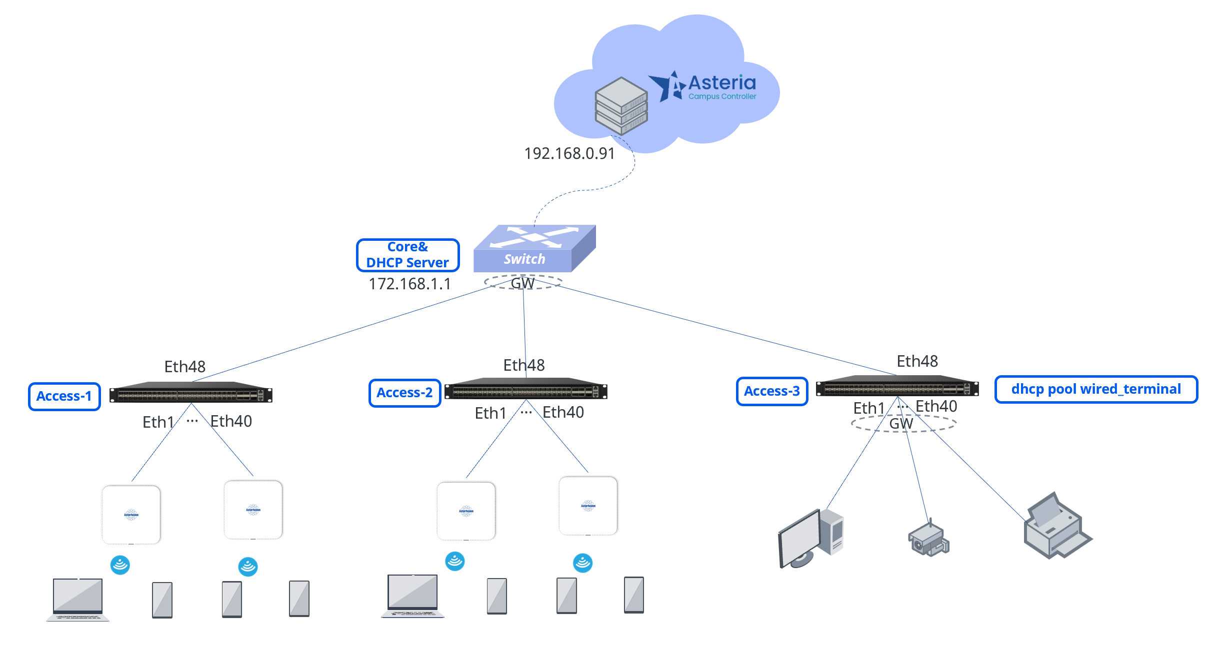
Network Architecture:
The Open Cloud Connect scenario allows users to flexibly configure Access devices. In the above network design, wireless networks are deployed on Access-1 and Access-2, while a wired network is deployed on Access-3. The gateways for the wireless networks are uniformly deployed on the Core, whereas the gateways for the wired network are deployed on the Access devices, making management and expansion more convenient.
DHCP Deployment:
The DHCP services for wireless terminals and AP management are deployed on the Core device, providing a consistent IP address acquisition point for wireless terminals and enabling seamless roaming. In contrast, the DHCP service for wired terminals is deployed on the Access devices, facilitating rapid fault localization and streamlining the troubleshooting process.
Controller Deployment:
The controller is cloud-deployed and managed uniformly via a graphical interface. It enables centralized policy distribution, configuration management, and status monitoring, significantly enhancing operational efficiency. Particularly for batch configuration and deployment of Access devices, it greatly reduces the workload.
Service Planning:
| Service Type | IP Segment | Gateway | Service VLAN | SSID |
|---|---|---|---|---|
| Wireless Service | 180.10.0.0/24 | 180.10.0.1/24 | 1080 | New SSID |
| Wired Service | 181.10.0.0/24 | 181.10.0.1/24 | 1081 | |
| AP Management | 182.10.0.0/24 | 182.10.0.1/24 | 1082 |
Device Import
Section titled “Device Import”Administrators can create or import devices in bulk to specified sites/organizations. When an added inventory device connects to the controller and comes online, the controller will automatically assign it to the designated organization/site based on its MAC address.
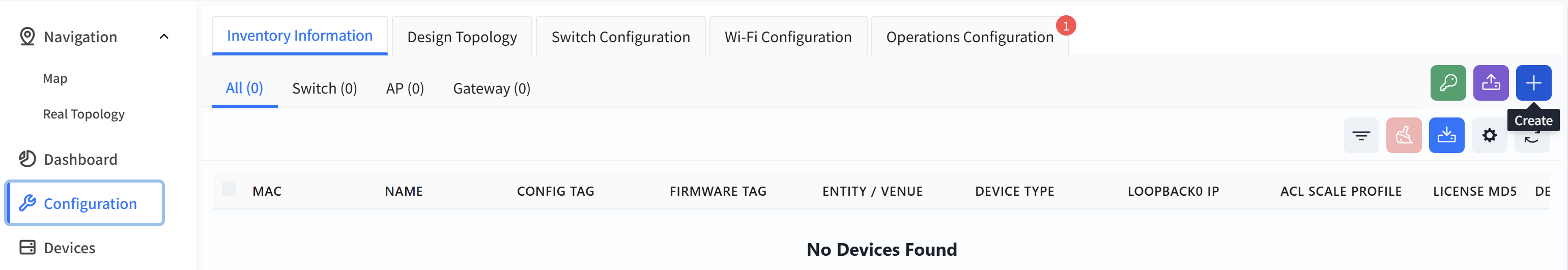
Add devices one by one.
Click [Configuration] - [Inventory Information] - [+] to create an inventory device.
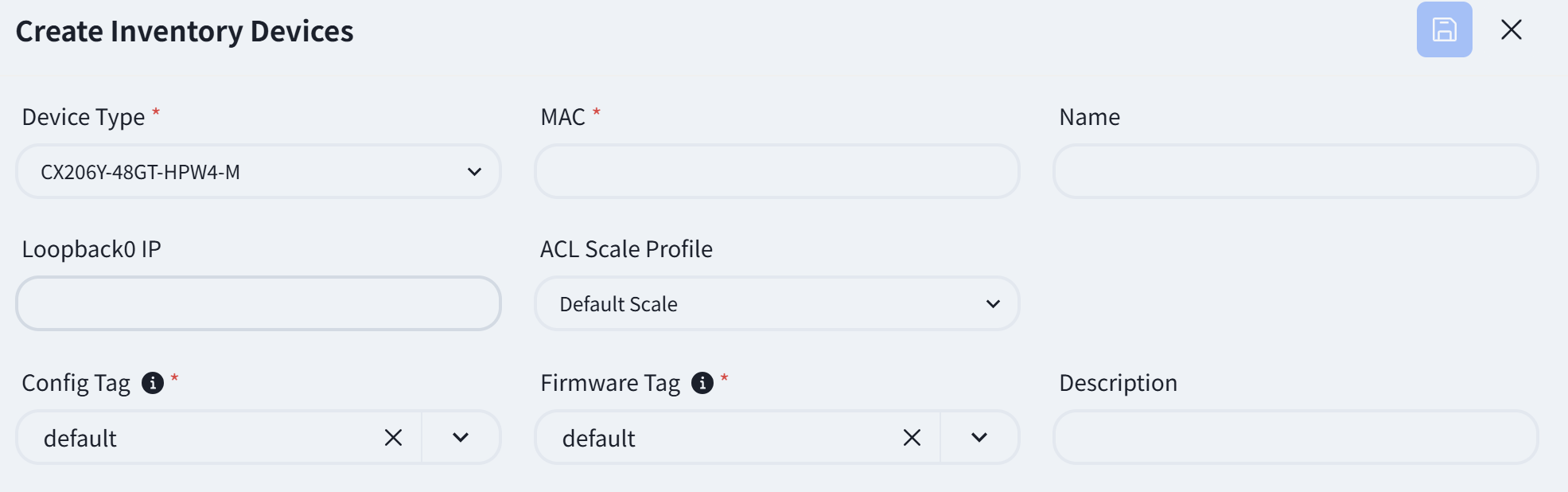
Fill in the relevant information as prompted on the page
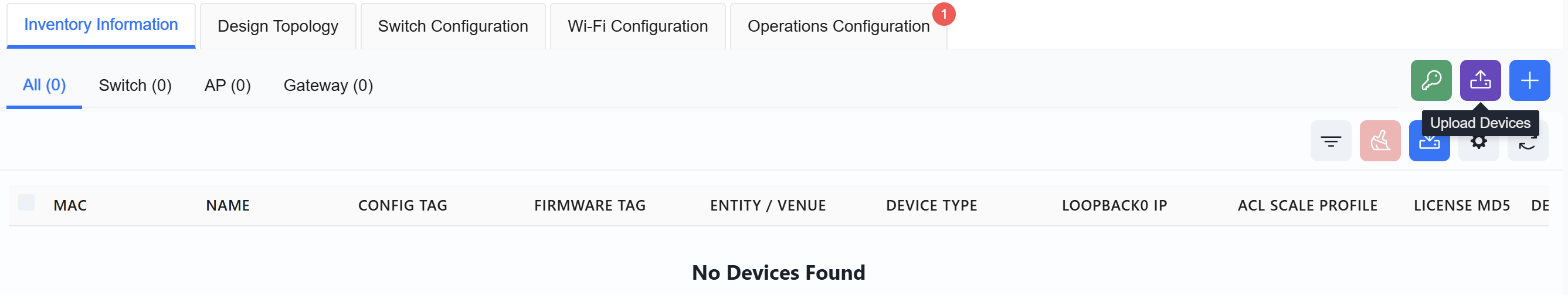
Import via Excel
Click [Upload Devices]
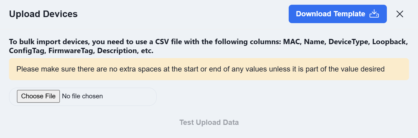
Click [Download Template] and enter the information for the devices to be added to the inventory according to the template’s specifications.
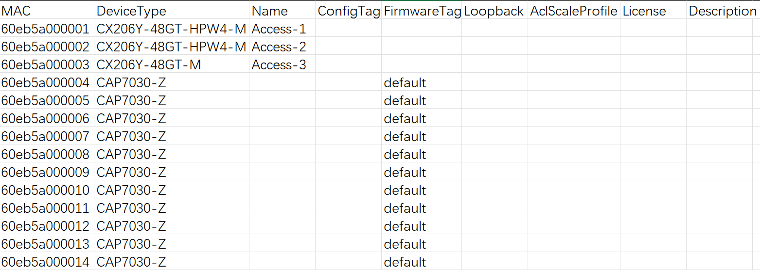
MAC: The device’s MAC address. This information is typically found on the device’s label.
Device Type: The device model.
Name: The device hostname. By default, it is the device’s MAC address.
ConfigTag: After an AP connects to the controller, it will automatically pull the configuration file corresponding to this tag. By default, the tag value is default.
FirmwareTag: When performing firmware upgrades, devices requiring an upgrade can be filtered based on their firmware tag type. By default, the tag value is default.
Loopback: The device’s loopback address. For all devices operating at Layer 3, this address serves as the device’s in-band management address.
AclScaleProfile: Optional values are default or large-scale. By default, the value is default.
License: The AP’s license file. For bulk imports, you can either enter the JSON-formatted license file content directly in the Excel sheet, or add all devices to inventory first and then import the license files in bulk afterward.
Description: Descriptive information about the device.
Click [Choose File] to upload the completed template, then click [Test Upload Data]. The controller will automatically check if the uploaded data complies with the specifications and display the results in the test report.
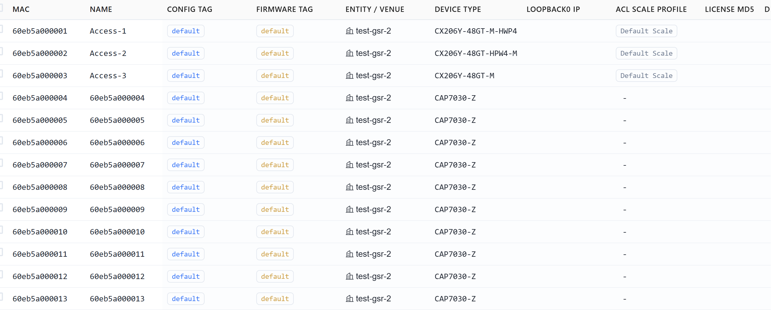
Once completed, users can view the created devices in the [Inventory Information] view.
Service Configuration
Section titled “Service Configuration”Design Topology
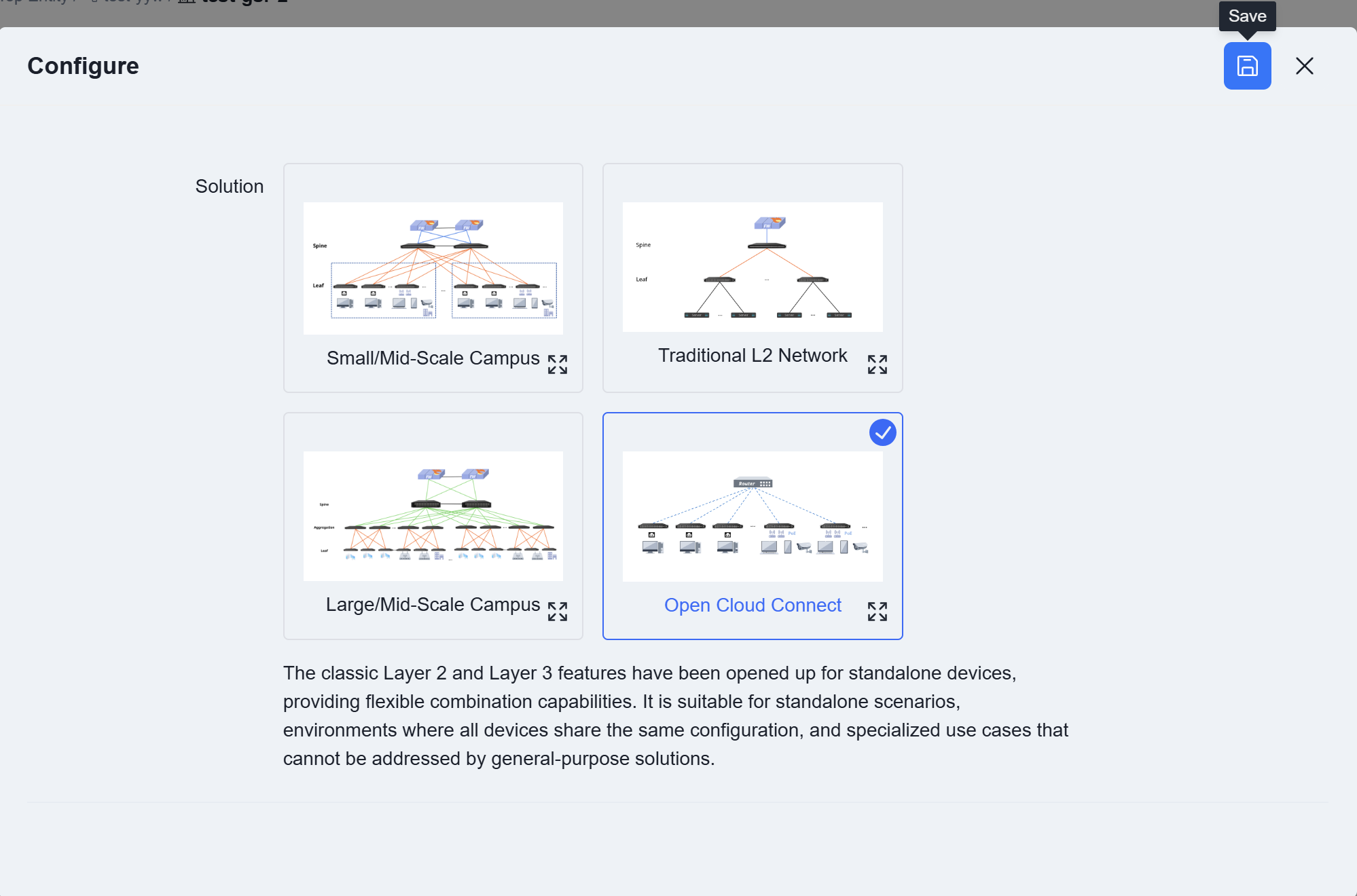
Section titled “Design Topology”Navigate to the [Configuration] view from the controller’s navigation bar, click [Design Topology], select [Open Cloud Connect], and then click [Save].
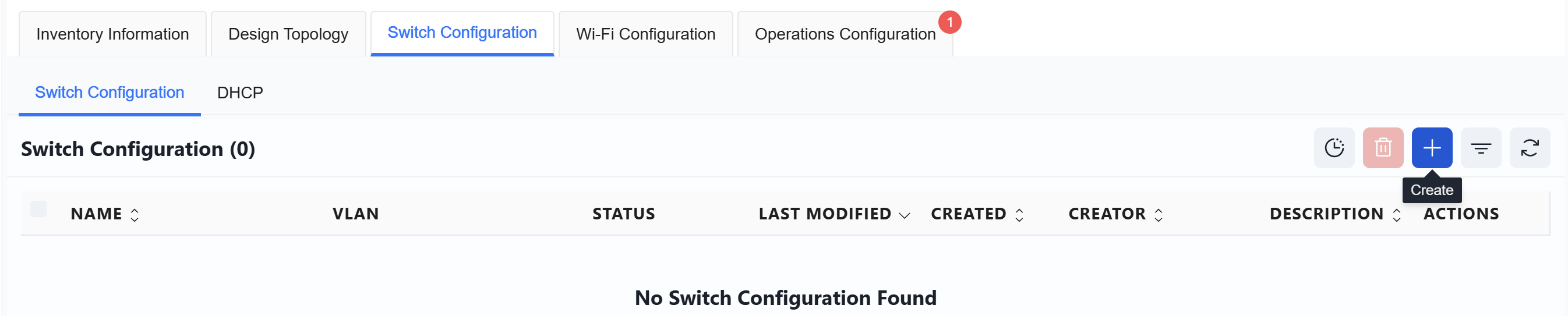
Switch Configuration
Section titled “Switch Configuration”Click [Create] on the right to set up the switch configuration.
Access-1
Section titled “Access-1”Create a switch configuration for Access-1:
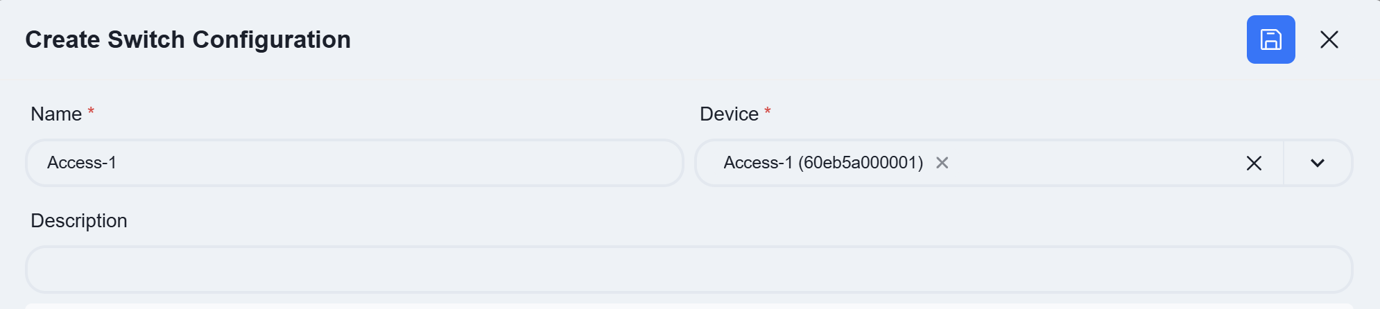
Name: User-defined
Device: Select the Access-1 device
| Procedure | Description |
|---|---|
| Step 1 | Configure Business VLAN Access-1 is a pure layer 2 configuration, where only business VLAN ID and member interface need to be specified. All other configurations are generated by the controller. Configuring the Wireless Business VLAN 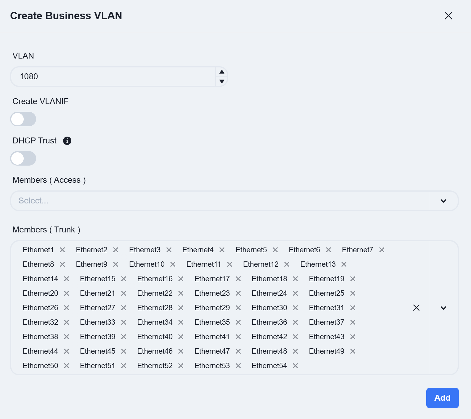 DHCP Trust: Authorizes the selected switch port to forward DHCP messages from legitimate DHCP servers. Ports not configured as “Trusted” are prohibited from doing so, fundamentally preventing DHCP spoofing attacks. Access/Trunk: Select the mode based on whether the interfaces send and receive frames with VLAN tags. * Access: Receives untagged frames. Typically configured for the AP management VLAN and wired service VLANs. |
- Trunk: Receives tagged frames. Typically configured for wireless service VLANs.
Members: Click the dropdown arrow to select the member interfaces for the VLAN on the device.
Configuring the AP Management VLAN:
Note: When the address allocation method for the VLANIF interface is set to Dynamic, the switch will obtain an IP address through the DHCP process. This IP address serves as the management address for the switch and resides in the same IP subnet as the management addresses of the APs. | | Step 2 | POE
The access switch features PoE functionality, which can be directly enabled in the wired service configuration to supply power to PD devices.
Click [Create]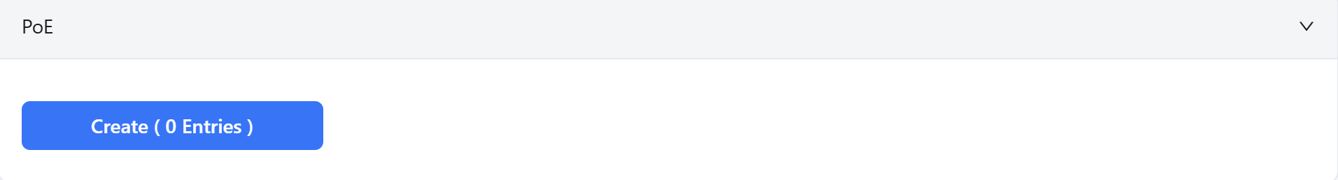
Select the interface where the PoE function is to be enabled and set the startup delay time.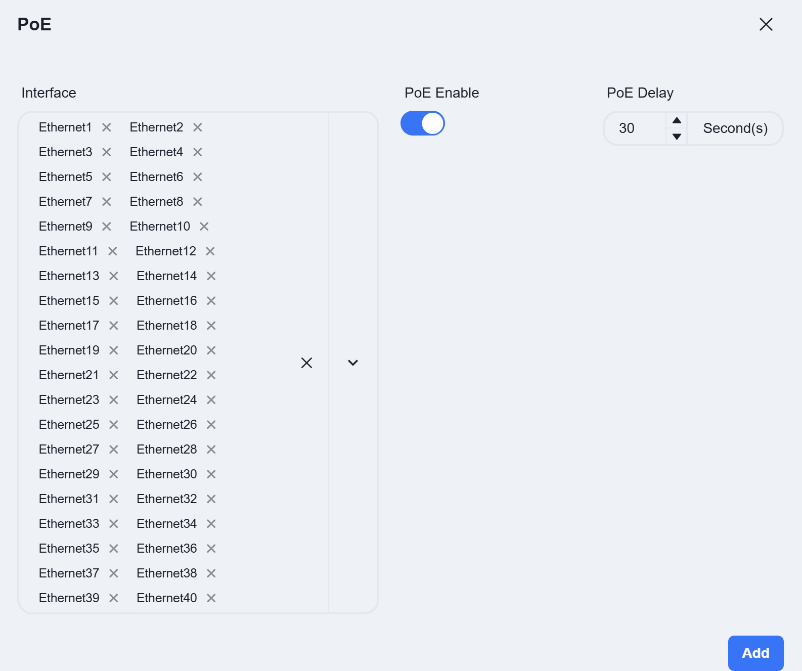 |
| Step 3 | Device
|
| Step 3 | Device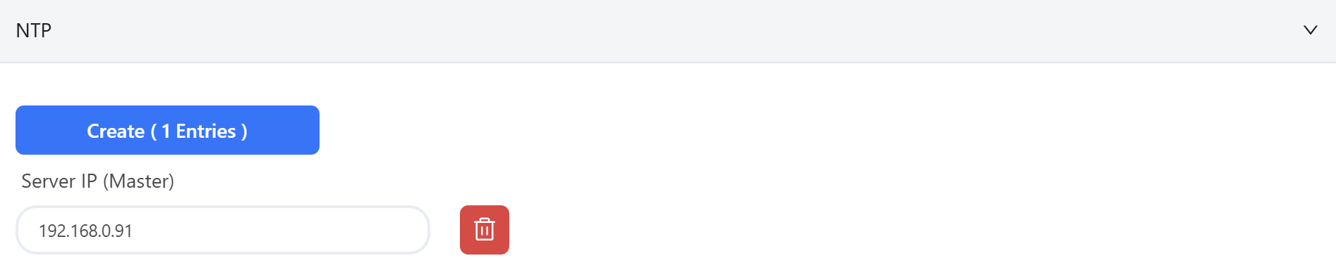
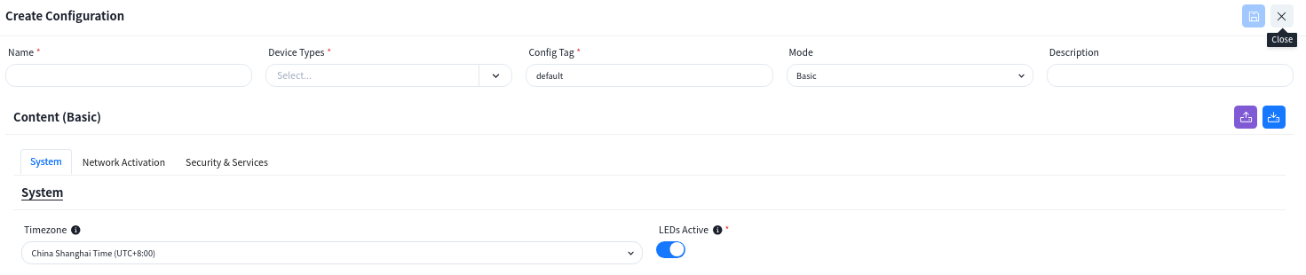
NTP: Configure the NTP server IP address as the Controller’s address to provide a unified, accurate, and reliable time reference for the devices. |
Access-2
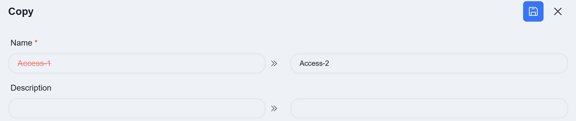
Section titled “Access-2”The configuration for Access-2 is identical to that of Access-1. Users can complete the entire setup by copying the configuration from Access-1 and then making targeted modifications.
Click the [Copy] button on the right.

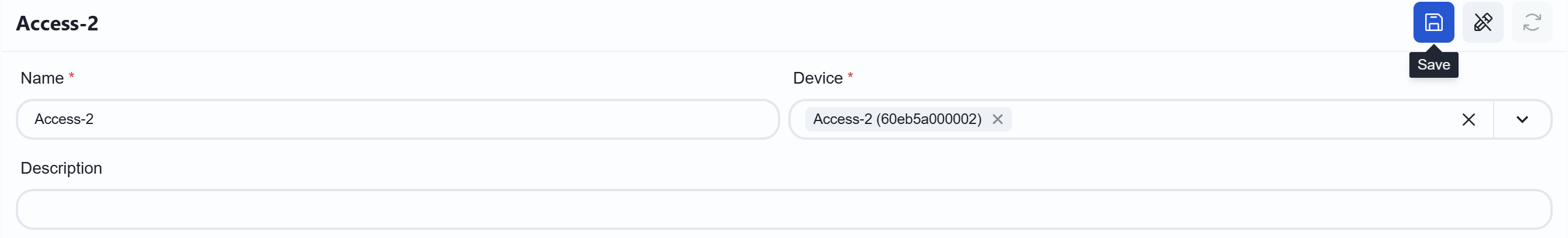
Change the configuration name and click [Save]
Click the [Edit] button on the right.
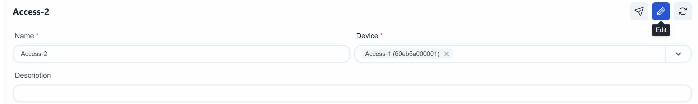
Change the device to Access-2. Once completed, click [Save] on the right.
Access-3
Section titled “Access-3”Deploy the wired service configuration on the Access-3 and deploy the wired service gateway.
| Procedure | Description |
|---|---|
| Step 1 | Configuring Routing Click [Create] 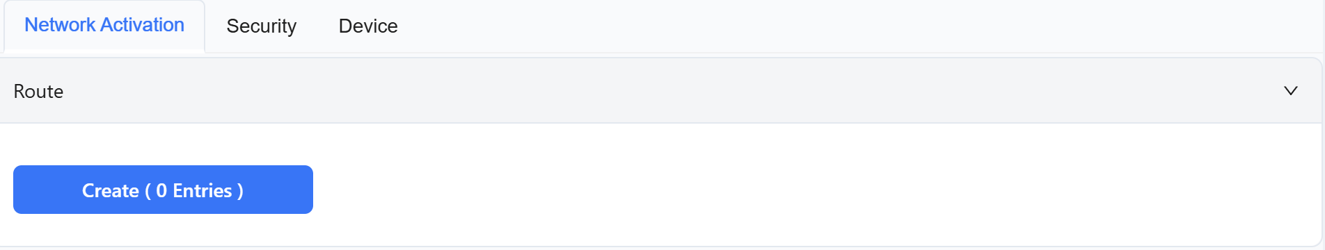 In this scenario, the Access device supports connecting to external networks by configuring static routes. To ensure normal network operation, a default route typically needs to be configured. The next-hop IP should be the uplink address of the Access device. Once completed, click [Add] 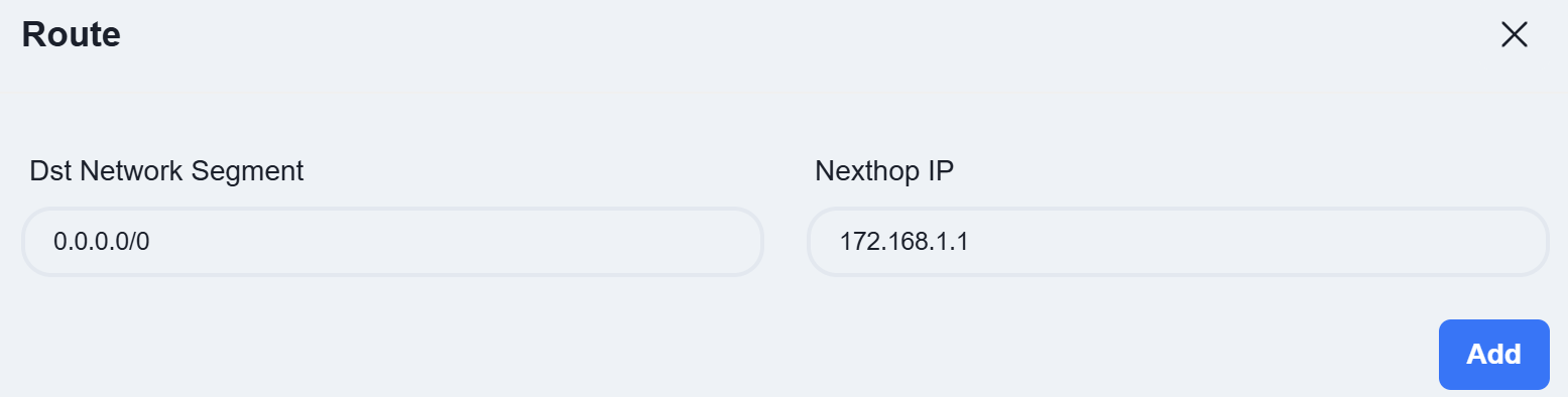 |
| Step 2 | Configure Business VLAN If the gateway is deployed on the Access device, you need to enable [Create VLANIF] when creating the service VLAN and fill in the [IP] address as the gateway for this service. 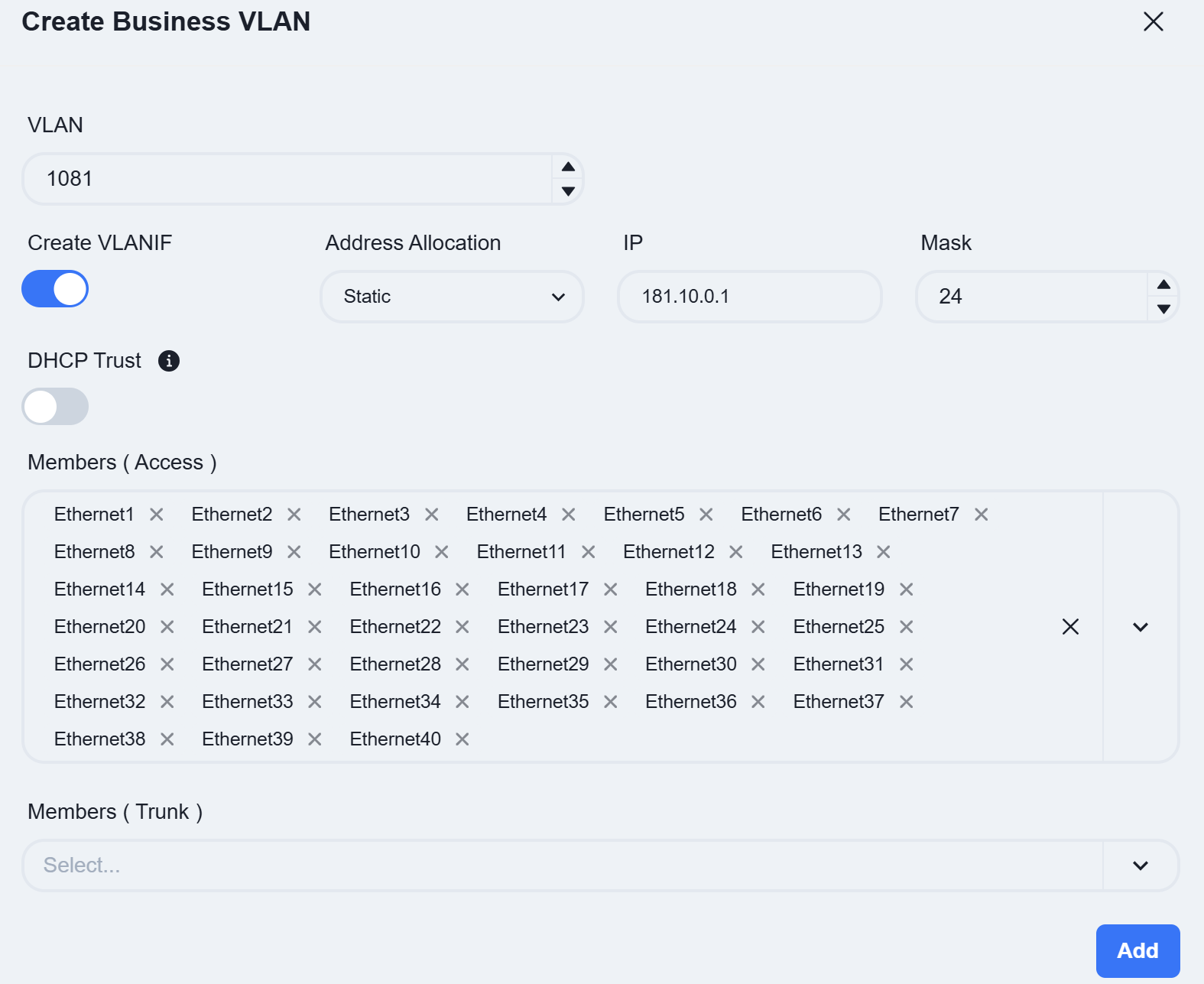 |
| Step 3 | DHCP Server The Open Cloud Connect scenario supports the deployment of a DHCP local service on Access devices. Click [Create] on the right side of IP Management. 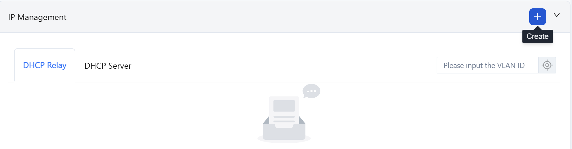 Select the IP Management method as [DHCP Server], choose VLAN as the wired service VLAN 1081, and click [Next] 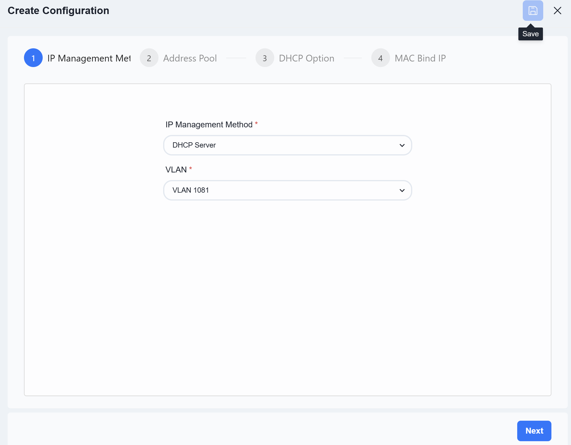 Configure the Network, Address Pool range, Gateway Address, and Lease Time. 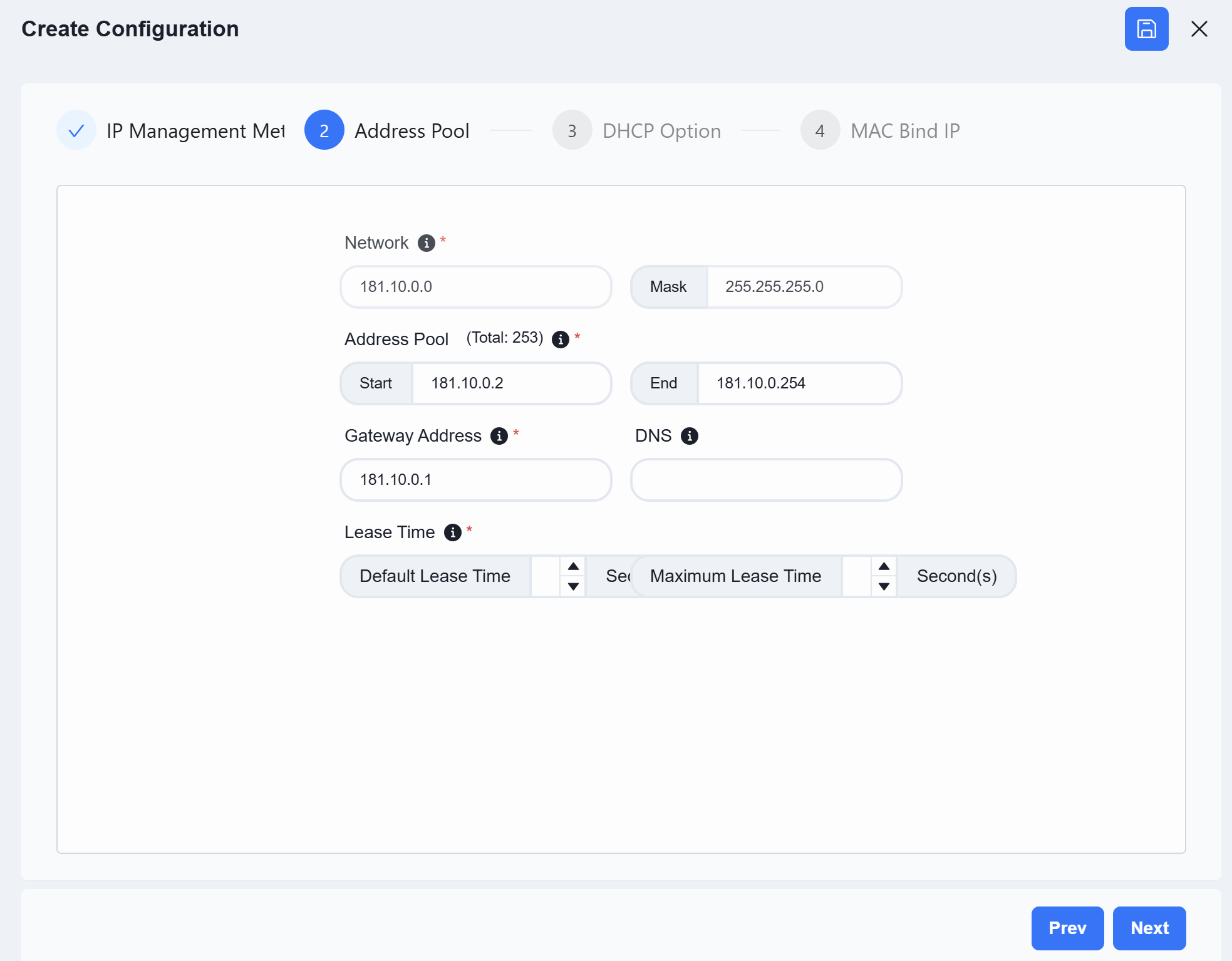 Configure MAC Bind IP (Optional). Once all configurations are complete, click [Save] in the upper-right corner. 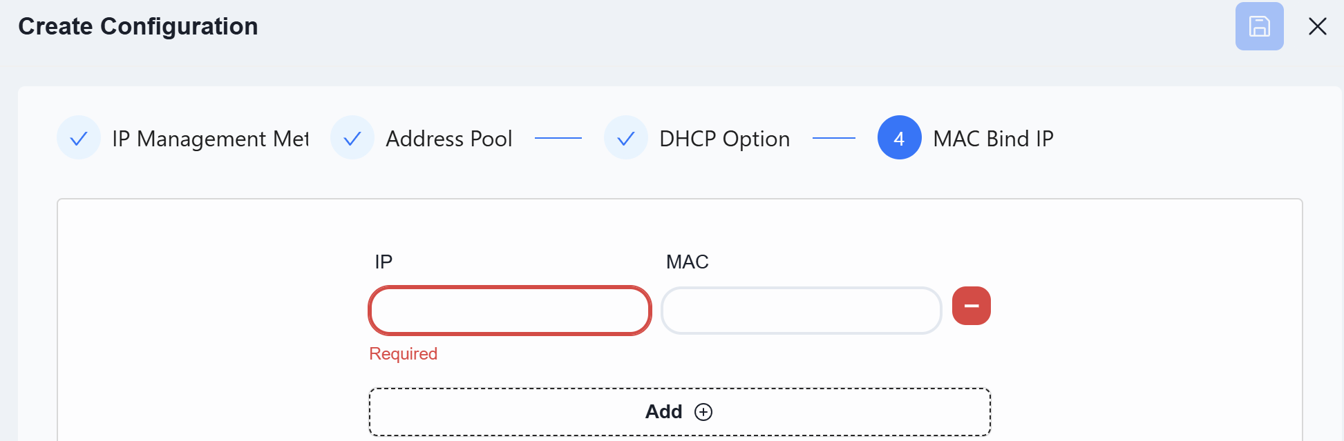 |
| Step 4 | Wired Clients Information Collection Interfaces with this feature enabled will report information about the connected wired terminals to the controller. 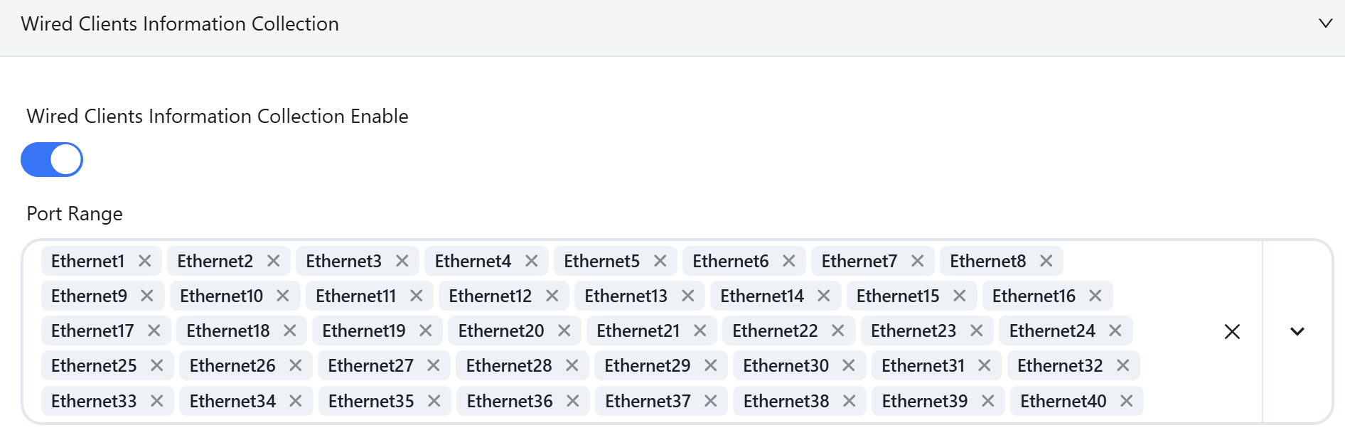 |
| Step 5 | Device Same as Access-1 |
Once all configurations are complete, click [Save] to finalize the Access-3 setup.
Wi-Fi Configuration
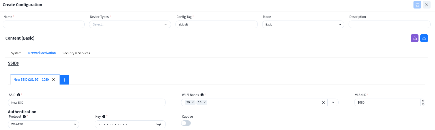
Section titled “Wi-Fi Configuration”Click [Wi-Fi Configuration] - [+] to configure the necessary basic information for the wireless AP, e.g. SSID settings, security policy. The controller can automatically generate the corresponding
The controller supports the configuration of different wireless service configurations, and after the AP goes online, it will determine which configuration should be issued to the AP based on the [Config Tag] attributes of the configuration.
LAN(Optional)
Section titled “LAN(Optional)”When the AP is one that has an extended wired interface and is capable of accessing terminals by wired means, such as a panel AP, the user can configure the access method for wired terminals through the configuration in LANs.
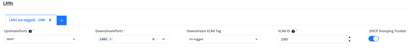
UpstreamPorts: Specify the up-link interfaces for wired terminal to access the network through AP, usually it is the interface for AP to connect to the switch, and keep the same with [UpstreamPorts] in [SSID] — [Advanced] Settings, the default is: WAN*.
DownstreamPorts: Interfaces for wired terminal access.
Downstream VLAN Tag: Whether the wired terminal carries VLAN Tag.
VLAN ID: The AP receives messages from wired terminals that add this VLAN TAG to identify.
DHCP Snooping Trusted: DHCP Snooping Trusted interface, if the wired terminal needs to obtain IP address through DHCP service, this switch needs to be on.
Configuration Release
Section titled “Configuration Release”Switch
Section titled “Switch”On the [Configuration]-[Switch Configuration] view, select the configuration to be deployed and click the [Push Configuration] button.
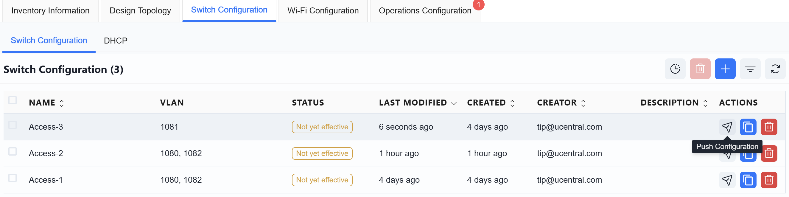
In the pop-up window, click [Next]-[Start] to deploy the switch configuration to the switch.
The AP does not need to manually issue the configuration. After the configuration of the device is issued and takes effect, the PoE power supply function of the switch is turned on, and the AP can power on and work. When the AP connects to the controller with the information obtained through the DHCP service, the controller will automatically send the configuration to the corresponding AP based on the comparison between the TAG identification stored in the AP inventory and the TAG identification in the planning configuration.