MSTP Configuration Guide
此内容尚不支持你的语言。
Introduction
Section titled “Introduction”MSTP (Multiple Spanning Tree Protocol) is a protocol for creating multiple spanning trees based on STP/RSTP. Introduced in IEEE 802.1s, it binds multiple STP instances to a smaller set of VLANs. MSTP inherits all the advantages of STP/RSTP while addressing the issue of link underutilization. By forming multiple loop-free trees, MSTP resolves broadcast storms and provides redundancy. The multiple trees achieve load balancing between VLANs, directing traffic along different paths for different VLANs.
Explanation of Principles
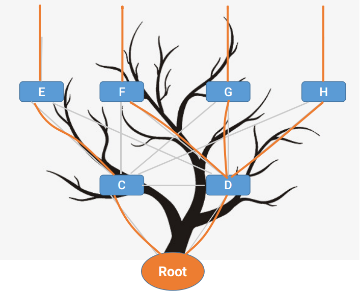
Section titled “Explanation of Principles”The principles and calculation methods of MSTP closely resemble those of STP/RSTP. The fundamental idea is to establish a loop-free tree structure by prioritizing comparisons, connecting devices from the highest-priority root node to lower-priority ones. This process transforms a cyclic network into a loop-free tree structure. The following diagram illustrates this concept:
MSTP Region
Section titled “MSTP Region”Unlike STP/RSTP, MSTP introduces the concept of regions, which divides the entire network into different regions composed of multiple devices and the segments between them. Devices within the same MSTP region share the following characteristics:
- All devices in the region run MSTP
- All devices have same region name
- All devices share the same VLAN-to-spanning-tree instance mapping configuration
- All devices share the same MSTP revision level configuration
A local area network can have multiple MSTP regions, and these regions can be directly or indirectly connected physically. Users can utilize MSTP configuration commands to group multiple devices into the same MSTP region.
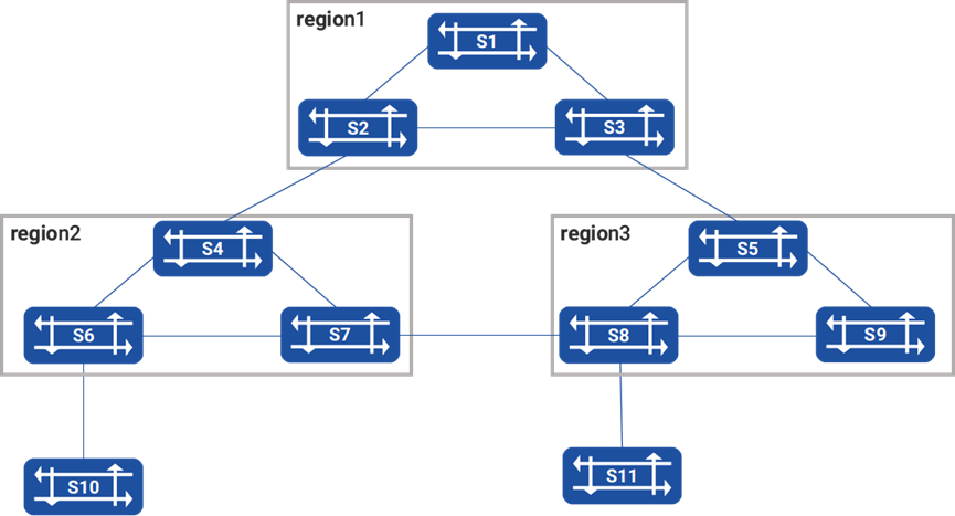
1.By configuring, three regions (region1 to region3) are formed as shown in the diagram.
2.In MSTP, instance 0 has a special significance known as CISTI (Common and Internal Spanning Tree Instance), while the remaining instances are referred to as MSTIs (Multiple Spanning Tree Instances). By default, all VLANs are bound to the CISTI, ensuring the security of the entire network.
3.The CIST (Common and Internal Spanning Tree) is calculated using the STP or RSTP protocol and forms a single spanning tree that connects all devices within a network. The IST (Internal Spanning Tree) of all MST regions combined with the CST (Common Spanning Tree) forms a complete spanning tree known as CIST. Within each region, it acts as IST, pruning devices to create a spanning tree; between regions, it acts as CST, treating each region as a single node and pruning them to form a spanning tree. The resulting effects are illustrated in the diagram.
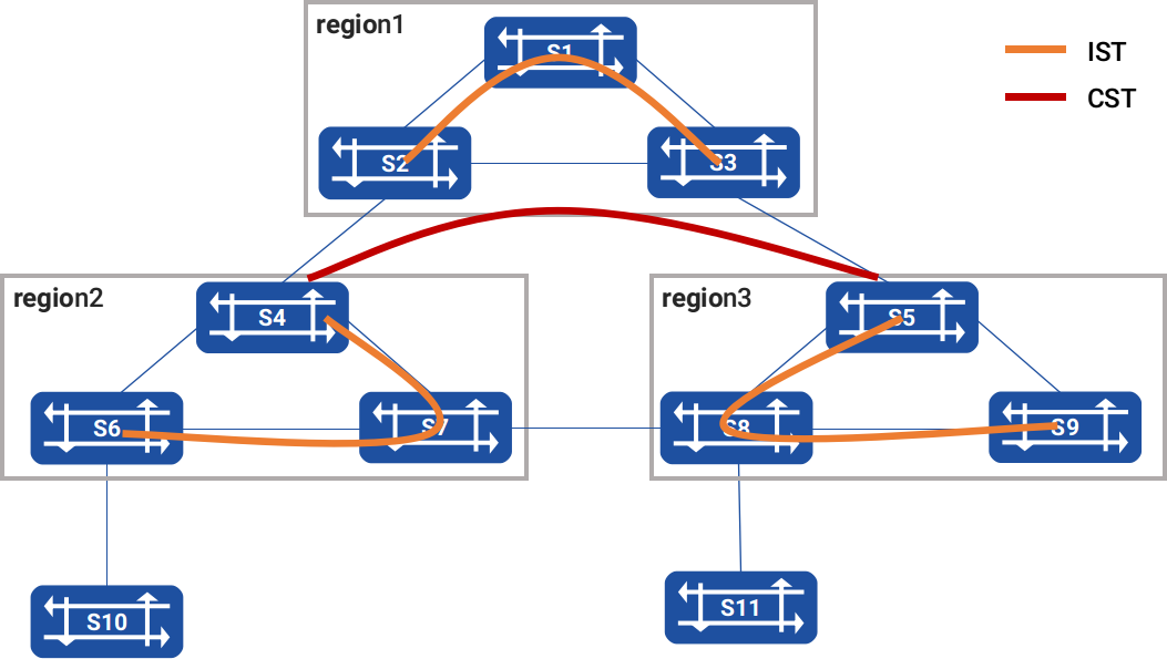
CIST prunes the circular network into a tree within each domain and trims the entire network into a loop-free tree across domains.
Due to the introduction of domains and instances, MSTP has two types of root nodes: the Common and Internal Spanning Tree Instance (CIST) root and the Domain root. The CIST root is a global concept and there is only one CIST root for all interconnected STP/RSTP/MSTP devices. It is also the root of the CIST. The Domain root, on the other hand, is specific to a particular domain and instance. It is a localized concept and is also the root of instance0 in region1.
MSTP Topology Calculation Principle
Section titled “MSTP Topology Calculation Principle”MSTP divides the entire network into multiple MST domains, treating each domain as a node. The calculations between different MST domains are performed using the STP or RSTP protocol algorithms to generate the Common Spanning Tree (CST), which is a single spanning tree. The calculation of the MSTP vector priority is as follows:
| Priority Vector Name | Description |
|---|---|
| Root bridge ID | The Root Bridge ID is used to select the root bridge in the Common and Internal Spanning Tree (CIST). It corresponds to the bridge ID in the BPDU and is calculated using the formula: Priority (16 bits) + MAC (48 bits). |
| External Root Path Cost (ERPC) | The path cost from an MST domain root to the overall root. The external root path cost stored on all devices within the MST domain is the same. If the CIST root bridge is within the domain, the external root path cost stored on all devices in the domain is 0 |
| Domain Root ID | Also known as the MSTI tree root, the Domain Root ID is used to select the root of the Multiple Spanning Tree Instances (MSTIs). It’s also elected based on the bridge ID and is calculated using the formula: Priority (16 bits) + MAC (48 bits) |
| Internal Root Path Cost (IRPC) | The path cost from the local device to the domain root bridge. Edge ports of the domain have a higher internal root path cost value (lower priority) compared to non-edge ports |
| Designated Bridge | The Designated Bridge for the CIST or an MSTI instance is the nearest upstream device to the local device on the path to the domain root. If the local device is the overall root or domain root, the Designated Bridge is itself |
| Designated Port | The Designated Port is the port on the Designated Bridge that is connected to the local device’s root port. Its Port ID = Priority (8 bits) + Port Number (8 bits) |
| Receiving Port | The Receiving Port is the port that receives the BPDU messages and its port priority must be a multiple of 16. Its Port ID = Priority (8 bits) + Port Number (8 bits). Port priority must be a multiple of 16 |
The lowest vector has the highest priority, and the comparison rules are as follows:
First, compare the Root Bridge ID. If the Root Bridge IDs are the same, proceed to compare the External Root Path Cost. If the External Root Path Costs are also the same, then compare the Domain Root IDs. If the Domain Root IDs are still the same, proceed to compare the Internal Root Path Costs. If the Internal Root Path Costs are still the same, then compare the Designated Bridge IDs. If the Designated Bridge IDs are still the same, proceed to compare the Designated Port IDs. If the Designated Port IDs are still the same, then compare the Receiving Port IDs.
- CSTI Calculation:
After the configuration message exchange comparison, select the device with the highest priority as the root of the CIST in the entire network. Then, within each MST domain, calculate the IST (Internal Spanning Tree) using the MSTP protocol algorithm. At the same time, MSTP treats each MST domain as a single device and calculates the CST (Common Spanning Tree) between MST domains using the STP or RSTP protocol algorithm.
The CST and IST together form the CIST for the entire device network.
- MSTI Calculation:
Within an MST domain, MSTP generates different spanning tree instances (MSTIs) for different VLANs based on the mapping between VLANs and instances. The characteristics of MSTI calculation are as follows:
- Each MSTI independently calculates its own spanning tree without interfering with others.
- The calculation method for the spanning tree in each MSTI is similar to RSTP.
- Each MSTI can have its own root and topology.
- Each MSTI sends its own BPDU within its own spanning tree.
- The topology of each MSTI is determined through configuration commands (not automatically generated).
- The parameters for each port in different MSTIs can be different.
- The role and status of each port in different MSTIs can also be different.
MSTI Spanning Tree Algorithm Implementation
At the beginning, each device’s ports generate configuration messages with itself as the root bridge. These messages have a root path cost of 0, the specified bridge ID as its own device ID, and the specified port as the current port. Each device sends out its own configuration message and processes other configuration messages it receives as follows:
- When a port receives a configuration message with a lower priority than its own (priority comparison is based on the vector priority comparison rules explained earlier), the device discards the received configuration message and takes no action on the configuration message for that port.
- When a port receives a configuration message with a higher priority than its own, the device replaces the content of the received configuration message with the content of the port’s own configuration message. Then, the device compares this port’s configuration message with the configuration messages on its other ports and selects the optimal configuration message.
Spanning Tree Calculation Steps
1.Root Bridge Election: By comparing the root bridge IDs in the configuration messages sent by all devices, the device with the smallest root bridge ID becomes the CIST root bridge or MST domain root bridge.
2.Root Port Election on Non-Root Bridges: Each non-root bridge designates the port that receives the best configuration message as its root port.
3.Designated Port Election: This step consists of the following two sub-steps:
1) Device calculates a standardized designated port configuration message for each port based on the root port's configuration message and root port's path cost. It replaces the root bridge ID with the root port's configuration message root bridge ID, adds the root port's path cost to the root port's configuration message root path cost, replaces the designated bridge ID with its own device ID, and replaces the designated port ID with its own port ID.
2) Device compares the calculated configuration message from the above rule with the original configuration message on the corresponding port. If the original configuration message is better, the port is blocked, and its configuration message remains unchanged. The port will only receive configuration messages but not forward data (acting as a root port). If the calculated configuration message is better, the device designates the port as the designated port, replaces the port's configuration message with the calculated one, and periodically sends it out.
4.After the MSTI spanning tree topology convergence, regardless of whether non-root bridges receive messages from the root bridge, they periodically send BPDUs according to the Hello timer. If a port does not receive a BPDU from the designated bridge (the higher-level device it is connected to) for 3 consecutive Hello times (default setting), the device considers the link to that neighbor as failed.
MSTP Configuration
Section titled “MSTP Configuration”Default Configuration
Section titled “Default Configuration”| Parameter | Default value |
|---|---|
| Spanning Tree Protocol Working Mode | MSTP mode |
| MSTP Function | Global MSTP function is not enabled, port-level MSTP function is not enabled |
| Instance Priority | 8 |
| Port Priority | 8 |
| Forward Delay Time | 15 seconds |
| Hello Time | 2 seconds |
| Max Age Time | 20 seconds |
MSTP Working Mode Configuration
Section titled “MSTP Working Mode Configuration”| Operation | Command | Description |
|---|---|---|
| Enter the system configuration view | configure terminal | |
| Enable MSTP | stp enable mstp |
MSTP Attribute Configuration
Section titled “MSTP Attribute Configuration”| Operation | Command | Description |
|---|---|---|
| Enter the system configuration view | configure terminal | |
| Configure MSTP forward delay | stp forward_delay time | Range value: 4-30 seconds |
| Configure MSTP hello packet interval | stp hello time | Range value: 1-10 seconds |
| Configure MSTP aging time | stp max_age time | Range value: 1-1000000 seconds |
| Configure MSTP domain | stp name name |
MSTP Instance Configuration
Section titled “MSTP Instance Configuration”| Operation | Command | Description |
|---|---|---|
| Enter the system configuration view | configure terminal | |
| Create an MSTP instance and enter the instance configuration mode | stp instance instance-id | |
| Bind a VLAN to the instance | stp bind vlan instance-id vlan-id | |
| Configure the instance priority | priority num | Range value: 0-15 |
| Configure port priority within the instance | port | Range value: 0-15 |
Display and Maintenance
Section titled “Display and Maintenance”| Operation | Command | Description |
|---|---|---|
| Display MSTP information | show stp mstp |
Configuration Example
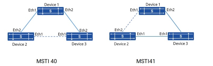
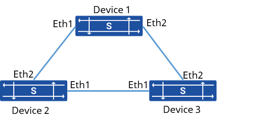
Section titled “Configuration Example”Network requirements
All devices in the network belong to the same MST domain, and by configuring MSTP, messages from different VLANs are forwarded according to different MSTIs.
Procedure
1.Device 1 configuraion
# Create VLAN 40, 41, and add the interface to the VLAN
sonic(config)# vlan 40sonic(config)# vlan 41sonic(config)# interface ethernet 1sonic(config-if-1)# switchport trunk vlan 40sonic(config-if-1)# switchport trunk vlan 41sonic(config)# interface ethernet 2sonic(config-if-2)# switchport trunk vlan 40sonic(config-if-2)# switchport trunk vlan 41# Enable MSTP function and configure the domain name of MST domain as test
sonic(config)# stp enable mstpsonic(config)# stp name test# Configure MSTI instance and configure the instance priority of this device
sonic(config)# stp instance 40sonic(config-stp-40)# priority 1sonic(config)# stp instance 41sonic(config-stp-41)# priority 5# Bind VLAN and MSTI instance
sonic(config)# stp bind vlan 40 40sonic(config)# stp bind vlan 41 412.Device 2 configuration
# Create VLAN 40, 41, and add the interface to the VLAN
sonic(config)# vlan 40sonic(config)# vlan 41sonic(config)# interface ethernet 1sonic(config-if-1)# switchport trunk vlan 40sonic(config-if-1)# switchport trunk vlan 41sonic(config)# interface ethernet 2sonic(config-if-2)# switchport trunk vlan 40sonic(config-if-2)# switchport trunk vlan 41# Enable MSTP function and configure the domain name of MST domain as test
sonic(config)# stp enable mstpsonic(config)# stp name test# Configure MSTI instance and configure the instance priority of this device
sonic(config)# stp instance 40sonic(config-stp-40)# priority 5sonic(config)# stp instance 41sonic(config-stp-41)# priority 5# Bind VLAN and MSTI instance
sonic(config)# stp bind vlan 40 40sonic(config)# stp bind vlan 41 413.Device 3 configuration
# Create VLAN 40, 41, and add the interface to the VLAN
sonic(config)# vlan 40sonic(config)# vlan 41sonic(config)# interface ethernet 1sonic(config-if-1)# switchport trunk vlan 40sonic(config-if-1)# switchport trunk vlan 41sonic(config)# interface ethernet 2sonic(config-if-2)# switchport trunk vlan 40sonic(config-if-2)# switchport trunk vlan 41# Enable MSTP function and configure the domain name of MST domain as test
sonic(config)# stp enable mstpsonic(config)# stp name test# Configure MSTI instance and configure the instance priority of this device
sonic(config)# stp instance 40sonic(config-stp-40)# priority 5sonic(config)# stp instance 41sonic(config-stp-41)# priority 1# Bind VLAN and MSTI instance
sonic(config)# stp bind vlan 40 40sonic(config)# stp bind vlan 41 41Verify configuration
1.View spanning tree information on Device 1
sonic# show stp mstpSpanning-tree Mode: mstpvlan mst instance port_role_state------ -------------- -------------------------------------------Vlan40 40 Ethernet1(Desg)(forw) Ethernet2(Desg)(forw)Vlan41 41 Ethernet1(Desg)(forw) Ethernet2(Root)(forw)2.View spanning tree information on Device 2
sonic# show stp mstpSpanning-tree Mode: mstpvlan mst instance port_role_state------ -------------- --------------------------------------------Vlan40 40 Ethernet1(Altn)(disc) Ethernet2(Root)(forw)Vlan41 41 Ethernet1(Root)(forw) Ethernet2(Altn)(disc)3.View spanning tree information on Device 3
sonic# show stp mstpSpanning-tree Mode: mstpvlan mst instance port_role_state------ -------------- --------------------------------------------Vlan40 40 Ethernet2(Root)(forw) Ethernet1(Desg)(forw)Vlan41 41 Ethernet2(Desg)(forw) Ethernet1(Desg)(forw)