
Policy Routing Configuration Guide
此内容尚不支持你的语言。
Introduction
Section titled “Introduction”Traditional route forwarding used to involve looking up the routing table based on the destination address of the packet and then forwarding the packet. However, an increasing number of users now wish to forward and select routes for packets based on their own defined policies in addition to traditional route forwarding. There are two different types of policy-based routing supported by the device:
1.ACL-based Policy Routing: Primarily used to control the flow of packets. ACL allows or denies packets passing through network devices and can filter based on conditions such as source IP address, destination IP address, port numbers, etc. ACL can be combined with policy routing to determine the direction of traffic by matching specific conditions of packets, thus implementing policy routing.
2.PBR-based Policy Routing: Mainly used to select different paths or next hops based on specific policies, rather than solely based on the traditional routing table. PBR allows defining the direction of traffic based on conditions such as source IP, destination IP, protocol, port, etc. It is a more flexible policy routing mechanism.
When dealing with smaller network scales and requiring simple traffic filtering and routing control, ACL-based policy routing can be chosen. When there is a need to implement more flexible routing policies such as multipath selection, failover, etc., PBR-based policy routing can be chosen.
Explanation of Principle
Section titled “Explanation of Principle”Policy routing is achieved by configuring redirection in the flow behavior, and it only takes effect on packets incoming on the interface. It is a mechanism for forwarding packets based on user-defined policies, with a priority higher than directly connected routes, static routes, and routes generated through dynamic routing protocols. After configuring policy routing on the device, if the received packet (including layer 2 packets) matches the rules of policy routing, it will be forwarded according to the rules; if the match fails, it will be forwarded according to the normal forwarding process based on the destination address.
Configuration
Section titled “Configuration”| Configuration tasks | Description | Index |
|---|---|---|
| Create and enter the policy routing view | Mandatory | |
| Create matching conditions for policy routing | Mandatory | |
| Specify the next hop for policy routing | Optional | |
| Create a next hop address group and enter the view | Optional | |
| Bind the policy routing to a specified interface | Optional |
Creating Policy Route
Section titled “Creating Policy Route”| Operation | Command | Description |
|---|---|---|
| Enter the system configuration view | configure terminal | |
| Create and enter the policy routing view | pbr-map name seq number | name: Specifies the name of the policy. number: Policy ID, with a range of 1-700. The lower the number, the higher the priority. |
Creating matching conditions for policy route
Section titled “Creating matching conditions for policy route”| Operation | Command | Description |
|---|---|---|
| Enter policy route view | pbr-map <name> seq <number> | |
| Create matching conditions for policy route | match {dst-ip<ip-address>|dst-port<port>|ip-protocol<protocol>|src-ip <ip-address>|src-port<port>} | dst-ip dst-port ip-protocol src-ip src-port |
| Set the source port for matching messages | src_interface <interface_num> | <interface_num>:Fill in the port name of the message source, such as Ethernet13. This configuration needs to be used in conjunction with SPI functionality to enable traceability matching of complete sessions |
Specifying the next hop for policy route
Section titled “Specifying the next hop for policy route”The “nexthop” command supports configuring up to 4 next hops. When multiple next hops are configured, packets are redirected and forwarded in a primary-backup manner. The primary and backup links are determined based on the configuration order, where the next hop IP address configured first has a higher priority as the primary link. In the event of a failure in the primary link, the backup link is automatically selected in order of configuration as the new primary link.
| Operation | Command | Description |
|---|---|---|
| Enter policy route view | pbr-map <name> seq | |
| Specify the next hop for policy route | set {nexthop <ip-address>|nexthop-group<name>} | nexthop nexthop-group: Specifies the name of the next hop address group. |
Creating Next Hop Address Group and Entering the View
Section titled “Creating Next Hop Address Group and Entering the View”When the next hop for policy routing is an address group, packets will be load balanced among the different next hops within the address group.
| Operation | Command | Description |
|---|---|---|
| Enter the system configuration view | configure terminal | |
| Create next hop address group | nexthop-group <name> | |
| Configure member addresses in the next hop address group | nexthop <ip-address> |
Binding the policy route to a specified interface
Section titled “Binding the policy route to a specified interface”| Operation | Command | Description |
|---|---|---|
| Enter the interface view | interface ethernet interface-id | |
| Bind the policy route to a specified interface | pbr-policy <name> |
Display and Maintenance
Section titled “Display and Maintenance”| Operation | Command |
|---|---|
| View the Binding Relationship between Policy Routing and Interfaces | show pbr interface [interface-name] |
| View Configured Policy Routes | show pbr map [MAP-NAME] |
| View Next Hop Address Groups for Policy Routing | show pbr nexthop-groups |
Example Configuration of Policy-Based Routing
Section titled “Example Configuration of Policy-Based Routing”Network requirements
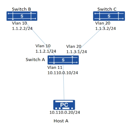
Control the packets received from interface Vlan11 of Switch A using policy-based routing:
- Specify the next hop for all TCP packets as 1.1.2.2
- Forward other packets using the traditional route table lookup method. Switch A is directly connected to Switch B and Switch C. There is no reachable route between Switch B and Switch C. Host A can successfully Telnet to Switch B but cannot Telnet to Switch C. Additionally, Host A can ping both Switch B and Switch C.
Procedure
1.IP addresses and VLAN configuration omitted 2.Configuration on Switch A:
# Create PBR rule
sonic(config)# pbr-map aaa seq 5sonic(config-pbr-map)# match ip-protocol tcpsonic(config-pbr-map)# set nexthop 1.1.2.2sonic(config-pbr-map)# exit# Apply the policy route map to interface
sonic(config)# interface vlan 11sonic(config-vlanif-11)# ip address 10.110.0.10/24sonic(config-vlanif-11)# pbr-policy aaasonic(config-vlanif-11)# exit# Configuration on Switch B and Switch C for static routes to Host A
sonic(config)# ip route 10.110.0.0/24 1.1.2.1sonic(config)# ip route 10.110.0.0/24 1.1.3.1Verify configuration
1.Verify the configuration
sonic# show pbr map detailpbr-map aaa valid: yes Seq: 5 rule: 304 Installed: 2(1) Reason: Valid IP Protocol Match: tcp nexthop 1.1.2.2 Installed: 1(1) Tableid: 100002.Perform Telnet and Ping from Host A, and verify if the results match the expectations:
Telnet from Host A to Switch B (telnet 1.1.2.2): Success
Telnet from Host A to Switch C (telnet 1.1.3.2): Failure
Ping from Host A to Switch C (ping 1.1.3.2): Success
Example of PBR strategy routing traceability matching scenario
Section titled “Example of PBR strategy routing traceability matching scenario”Network requirements
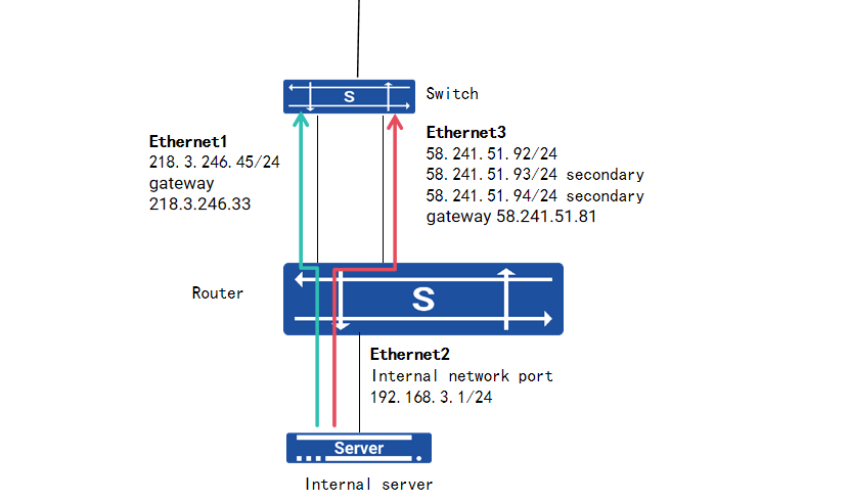
In the following network setup, traffic from external networks accessing the internal network via the Router device is restricted. The enterprise requires that public internet traffic entering through the two public network ports (Ethernet1 and Ethernet3) can access the same internal service. When all links are functioning normally, PBR (Policy-Based Routing) must be implemented to trace and mark traffic originating from different public network ports. Simultaneously, the SPI (Stateful Packet Inspection) function should be enabled to maintain session records. This ensures that return traffic from the internal network port (Ethernet2) to different public network ports can correctly identify the corresponding egress interfaces and next hops.
Procedure
interface ethernet 2ip address 192.168.3.1/24pbr-policy srcifstateful-packet-inspection enable tcpnat static tcp 58.241.51.92 2022 192.168.3.10 5201 dnat extendable test1nat static tcp 218.3.246.45 2022 192.168.3.10 5201 dnat extendable test2pbr-map srcif seq 5match src-ip 192.168.3.10/24match ip-protocol tcpset nexthop 58.241.51.95src_interface 3pbr-map srcif seq 6match src-ip 192.168.3.10/24match ip-protocol tcpset nexthop 218.3.246.33src_interface 1