
NAT-VPP Case
此内容尚不支持你的语言。
Introduction
Section titled “Introduction”This guide provides a step-by-step tutorial for configuring the Network Address Translation (NAT) capabilities of the Asterfusion ET2500 Open Intelligent Gateway running AsterNOS-VPP.
What This Guide Will Accomplish
Section titled “What This Guide Will Accomplish”By following this guide, you will start with an unconfigured AsterNOS VM and progressively build a complete, policy-based NAT gateway. The scenarios covered are:
- Policy-Based SNAT : Configuring the gateway to intelligently apply NAT to one internal network (VLAN 10) while allowing another (VLAN 20) to be routed without NAT.
- DNAT (Destination NAT) : Publishing a service from the private internal network (VLAN 10) to the outside world, making it accessible via the gateway’s public IP address.
- Multi-Pool SNAT : Modifying the initial configuration to apply NAT to both internal networks (VLAN 10 and VLAN 20), intelligently mapping each VLAN to its own dedicated public IP address from a NAT pool.
Preparation and Environmental Overview
Section titled “Preparation and Environmental Overview”Topology map
Section titled “Topology map”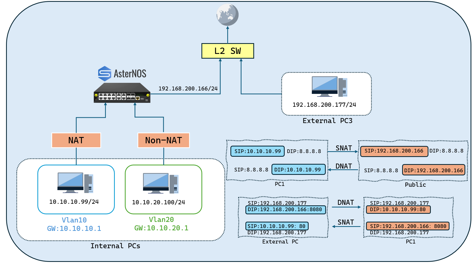
Network Planning and Preparation
Section titled “Network Planning and Preparation”Before you begin, please prepare your lab environment. The only prerequisite tasks are to physically connect the devices as shown in the topology and pre-configure the static IP addresses on the two end-user PCs (the Internal Server PC and the External Client PC).
The AsterNOS VM should start in a clean, unconfigured state. This guide will walk you through the steps to configure your AsterNOS VM to match the target configuration planoutlined in the table below.
- Lab Components (Phase 1):
| Device Type/Operating System | Role in Topology | Key Function in This Guide |
|---|---|---|
| ET2500 / AsterNOS | NAT Gateway | Device Under Test (DUT) for NAT configuration. |
| Physical PC / Windows | Internal Server (VLAN 10) | Server in the NAT zone (VLAN 10). |
| Physical PC / Windows | Internal Client (VLAN 20) | Client in the Non-NAT zone (VLAN 20). |
| Physical PC / Windows | External Client | External user for testing DNAT. |
- Target Configuration Plan (Phase 1):
| Device/Logical Interface | IP Address/Subnet | Default Gateway | Notes/Connection Point |
|---|---|---|---|
| AsterNOS VM (WAN) | 192.168.200.166/24 | 192.168.200.1 | Connects via Ethernet1 to External Switch |
| AsterNOS VM (VLAN 10 GW) | 10.10.10.1/24 | - | Logical Gateway for VLAN 10 (interface vlan 10) |
| AsterNOS VM (VLAN 20 GW) | 10.10.20.1/24 | - | Logical Gateway for VLAN 20 (interface vlan 20) |
| Internal Server PC | 10.10.10.99/24 | 10.10.10.1 | In VLAN 10, connects to AsterNOS Ethernet2 |
| Internal Client PC | 10.10.20.100/24 | 10.10.20.1 | In VLAN 20, connects to AsterNOS Ethernet3 |
| External Client PC | 192.168.200.177/24 | 192.168.200.1 | Connects to External Switch |
| Upstream Gateway | 192.168.200.1 | (To Internet) | Provides Internet access for the WAN segment |
- Required Tools:
To verify the DNAT configuration in Part Four, we will use the Netcat (ncat.exe) utility. Please prepare this tool in advance and place it in an easily accessible location (e.g., the Desktop) on both PCs.
Building the Basic Network
Section titled “Building the Basic Network”This section covers the initial setup of the WAN interface, internal VLANs, and all necessary IP addresses to build our network foundation. This prepares the gateway for the advanced policy-based NAT configuration in the next part.
Configuration steps
Section titled “Configuration steps”- Step 1: Login and Enter Configuration Mode
First, log in to the AsterNOS-VPP virtual machine. The default credentials are admin / asteros. After logging in, you will be at the Linux shell prompt (admin@sonic:~$).
Enter the AsterNOS command-line interface (CLI).
admin@sonic:\~$ sonic-cliEnter the global configuration mode.
sonic# configure terminal- Step 2: Configure WAN Interface and Default Route
Configure the external-facing Ethernet1 interface and set the default route for all outbound internet traffic.
Configure the WAN Interface
sonic(config)# interface ethernet 1sonic(config-if-1)# ip address 192.168.200.166/24sonic(config-if-1)# no shutdownsonic(config-if-1)# exitConfigure the Default Route
#Remember to replace 192.168.200.1 with your actual upstream gateway's IP address.sonic(config)# ip route 0.0.0.0/0 192.168.200.1- Step 3: Configure Internal VLANs and Interfaces
Now, we will create two separate internal networks (VLAN 10 and VLAN 20) and assign a physical port to each.
Create the VLANs
sonic(config)# vlan 10sonic(config-vlan-10)# exitsonic(config)# vlan 20sonic(config-vlan-20)# exitConfigure Ethernet2 as an Access Port for VLAN 10
sonic(config)# interface ethernet 2sonic(config-if-2)# no router-interfacesonic(config-if-2)# switchport access vlan 10sonic(config-if-2)# no shutdownsonic(config-if-2)# exitConfigure Ethernet3 as an Access Port for VLAN 20
sonic(config)# interface ethernet 3sonic(config-if-3)# no router-interfacesonic(config-if-3)# switchport access vlan 20sonic(config-if-3)# no shutdownsonic(config-if-3)# exitConfigure the Layer 3 Gateway Interfaces (SVIs) for each VLAN
Configure the gateway for VLAN 10sonic(config)# interface vlan 10sonic(config-vlanif-10)# ip address 10.10.10.1/24sonic(config-vlanif-10)# exit # Configure the gateway for VLAN 20sonic(config)# interface vlan 20sonic(config-vlanif-20)# ip address 10.10.20.1/24sonic(config-vlanif-20)# exitVerification: Check Basic Connectivity
Section titled “Verification: Check Basic Connectivity”Before proceeding, verify that both internal PCs can communicate with their respective gateways.
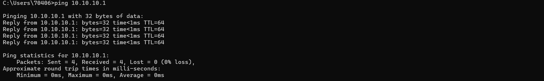
- Command: From your Internal Server PC (10.10.10.99), ping its gateway.
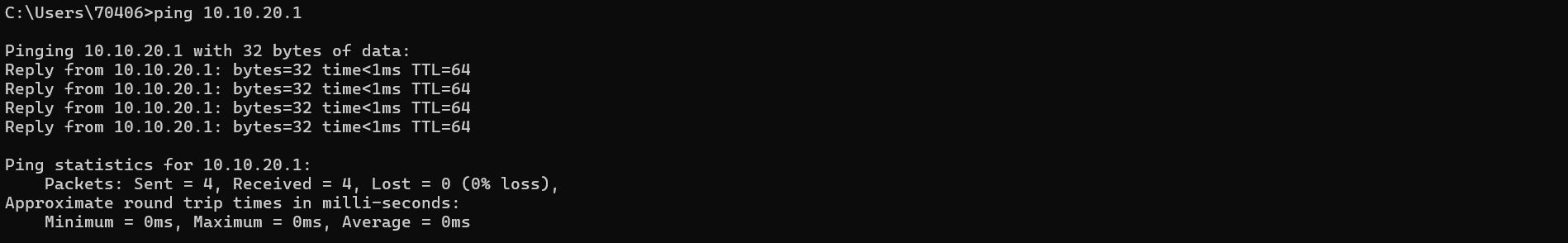
ping 10.10.10.1- Command: From your Internal Client PC (10.10.20.100), ping its gateway.
ping 10.10.20.100- Conclusion: If both pings are successful, your basic network structure is correctly configured, and you are ready to proceed to the next part.
Differentiated Outbound Access - Policy-Based NAT
Section titled “Differentiated Outbound Access - Policy-Based NAT”This section is the core of our advanced configuration. We will create an intelligent Access Control List (ACL) to apply different NAT policies to VLAN 10 and VLAN 20, perfectly replicating the logic from the ISR topology diagram.
Configuration steps
Section titled “Configuration steps”-Step 1: Define the NAT Boundary and Enable NAT Globally
First, we must activate the NAT engine and define the external-facing interface as the boundary where NAT policies are enforced.Define the WAN Interface as the NAT Boundary
sonic(config)# interface ethernet 1sonic(config-if-1)# nat-zone 1sonic(config-if-1)# exitEnable the NAT Service Globally
sonic(config)# nat enable-Step 2: Create the “Smart” ACL for Policy Control
This ACL will act as our “traffic director.” It contains rules to explicitly exempt VLAN 20 traffic from NAT while permitting VLAN 10 traffic for NAT processing. Rule priority is determined by the rule ID number; higher numbers are processed first.
Create the ACL Table
sonic(config)# access-list L3 SMART_NAT_ACL ingressCreate Rule to Exempt VLAN 20 (High Priority)
This rule matches traffic from the VLAN 20 subnet and applies the*** no-nat***action, instructing the NAT engine to bypass it.
sonic(config-l3-acl-SMART_NAT_ACL)# rule 20 packet-action no-nat src-ip 10.10.20.0/24Create Rule to Permit VLAN 10 (Low Priority)
This rule matches traffic from the VLAN 10 subnet and applies the permit action, allowing it to be processed by the NAT engine.
sonic(config-l3-acl-SMART_NAT_ACL)# rule 10 packet-action permit src-ip 10.10.10.0/24 #exitsonic(config-l3-acl-SMART_NAT_ACL)# exit-Step 3: Deploy the ACL and the Global SNAT Engine
With the policy defined, we now deploy it to the VLAN interfaces and create the NAT “execution engine” that will handle the permitted traffic.
Deploy the “Smart” ACL to Both VLAN Interfaces
By binding the ACL to the VLAN interfaces, we ensure all traffic entering the routing engine is first classified by our policy.
Bind ACL to VLAN 10sonic(config)# interface vlan 10sonic(config-vlanif-10)# acl SMART_NAT_ACLsonic(config-vlanif-10)# exit # Bind the same ACL to VLAN 20sonic(config)# interface vlan 20sonic(config-vlanif-20)# acl SMART_NAT_ACLsonic(config-vlanif-20)# exitCreate the Global SNAT Engine
This simple NAT binding will process any traffic that is permitted by the ACL.
Create the NAT address poolsonic(config)# nat pool WAN_POOL 192.168.200.166 # Create a global NAT binding without an ACLsonic(config)# nat binding GLOBAL_SNAT WAN_POOLVerification: Check NAT Translations
Section titled “Verification: Check NAT Translations”-Verify the NAT Path (VLAN 10)
- From yourInternal Server PC (10.10.10.99), ping its gateway.
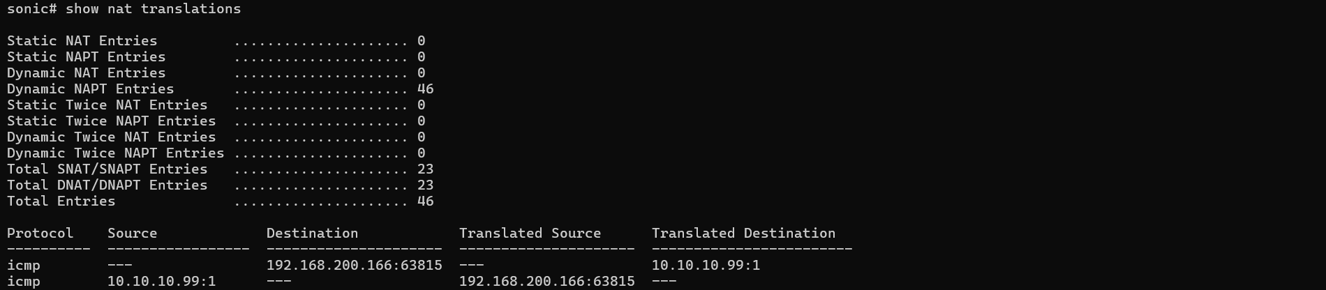
ping -t 8.8.8.8- On the AsterNOS VM,check the NAT table
sonic# show nat translations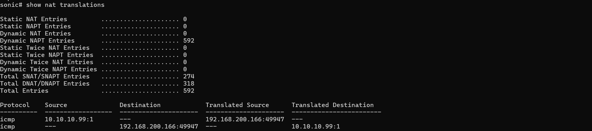
-Verify the Non-NAT Path (VLAN 20)
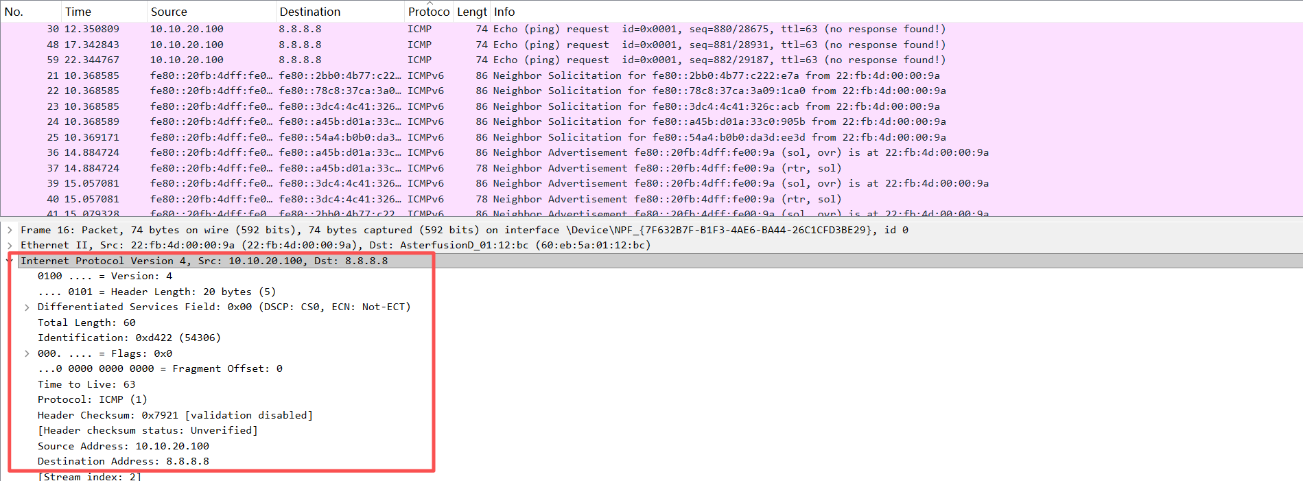
To definitively prove that VLAN 20 traffic is being routed without NAT, we must capture the packets as they exit the WAN interface using Port Mirroring (SPAN).
Configure SPAN on the AsterNOS VM.
This will copy all traffic exiting the WAN port (Ethernet1) to an unused port (e.g.,Ethernet4).
sonic(config)# mirror session 1 span direction tx src-ethernet 1 dst-ethernet 4Connect a separate PC with Wiresharkto the physical port corresponding to Ethernet4 and start capturing traffic.
While capturing,on the Internal Client PC (10.10.20.100), start a standard ping:
ping -t 8.8.8.8Expected Result:
In the Wireshark capture, you will see ICMP packets with the original, untranslated source IP address. This is the definitive proof that the no-nat rule is working as intended.
Publishing an Internal Service - DNAT Configuration and Verification
Section titled “Publishing an Internal Service - DNAT Configuration and Verification”Now that outbound traffic is working, the final part is to configure DNAT (Destination Network Address Translation). This will allow external users to access a service running on your private internal network. This is commonly known as “port forwarding.”
Configuration steps
Section titled “Configuration steps”Step 1: Add the DNAT Port Forwarding Rule and Save Configuration
This step tells the gateway to forward incoming traffic on a specific public port to our internal server. After adding this final rule, we will save the entire configuration to ensure it persists after a reboot.
- On your AsterNOS VM, enter the global configuration mode (sonic(config)#).
- Add the static DNAT rule. This rule maps port 8080 on the public IP to port 80 on the internal server.
sonic(config)# nat static tcp 192.168.200.166 8080 10.10.10.99 80 dnat- Save the complete configuration.
sonic(config)# exitsonic# writeStep 2: Prepare the Internal Test Service
To verify the DNAT rule, we need a simple service running on our internal server that can accept the forwarded connections. We will use the versatile Netcat tool for this.
- On your Internal Server PC (10.10.10.99), open a Command Prompt (CMD).
- Navigate to the directory where you have placed ncat.exe.
- Start Netcat in listening mode on port 80. It will now act as a simple server.
C:\Users\YourUser> ncat -l -p 80Verification
Section titled “Verification”With the DNAT rule configured and the internal service running, we will perform a final end-to-end test.
- Verification Operation
- On your External Client PC (192.168.200.177), open a new Command Prompt (CMD).
- Navigate to the directory where you have placed ncat.exe.
- Use Netcat to connect to the public IP and forwarded port of the AsterNOS gateway.
C:\Users\YourUser> ncat 192.168.200.166 8080- Delving into the Data Plane: Capturing the Evidence
On your AsterNOS VM, while the Netcat connection is active, go to the Linux shell.
Execute the following command to find the session related to your External Client PC.
sudo docker exec syncd vppctl show nat44 sessions | grep 192.168.200.177Expected Result and Interpretation The output will show a complete TCP session entry, proving that both DNAT and the return-path SNAT are working in the data plane.

The o2i (Outside-to-Inside) flow line is the DNAT proof.
It shows a packet from the External Client (192.168.200.177) destined for the public port (192.168.200.166:8080) being rewritten with the new destination of the Internal Server (10.10.10.99:80).
The i2o (Inside-to-Outside) flow line is the return SNAT proof.
It shows the reply from the Internal Server (10.10.10.99:80) has its source rewritten to appear as if it came from the gateway’s public port (192.168.200.166:8080).
-
Conclusion:
The successful two-way communication, combined with this specific data plane evidence, provides definitive proof that your NAT Gateway is fully and correctly configured for both SNAT and DNAT operations.
(Advanced) Upgrading to Multi-Pool Policy NAT
Section titled “(Advanced) Upgrading to Multi-Pool Policy NAT”This section guides you through modifying the completed Phase 1 configuration to achieve a more advanced NAT scenario.Our New Goal: Instead of exempting VLAN 20 from NAT, we will now apply NAT to both internal networks, but intelligently map each VLAN to its own dedicated public IP address.
This guide assumes you have completed Phase 1 and are starting from that final configuration state. We will now modify it.
Topology map
Section titled “Topology map”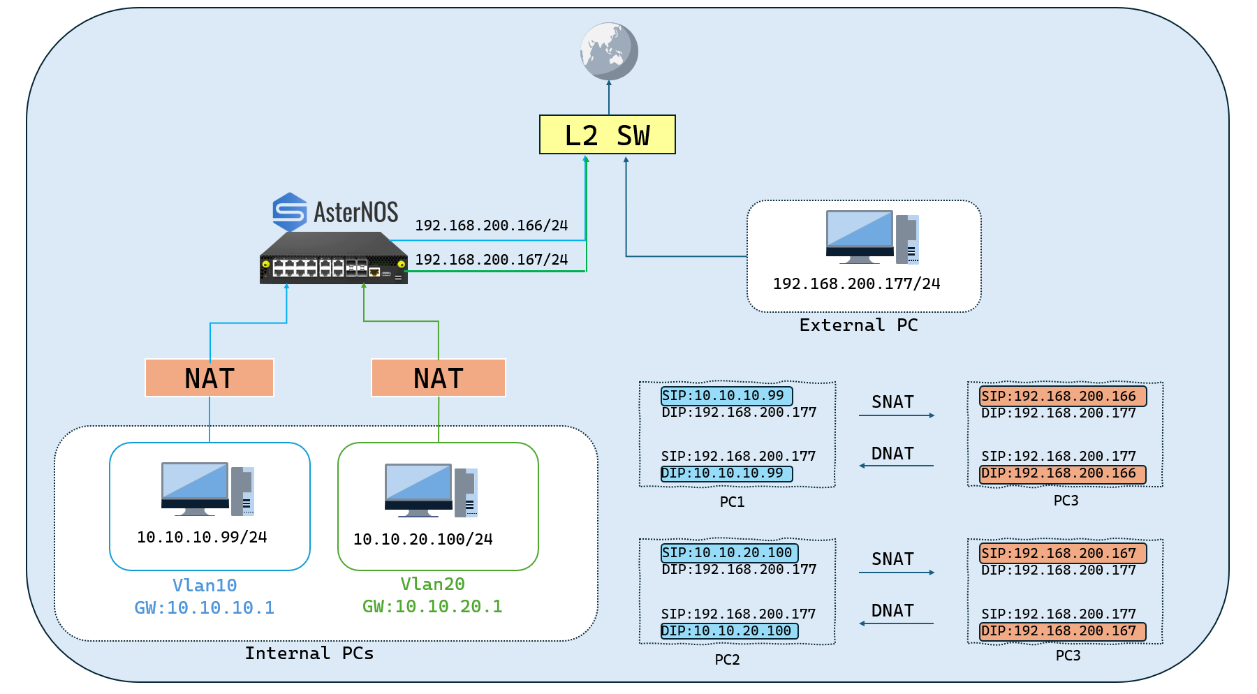
Network Planning and Preparation
Section titled “Network Planning and Preparation”With our new goal, the logical configuration of our network components will be updated. The key changes are:
- The NAT Gateway will now be assigned two public IP addresses on its WAN interface.
- TheInternal Client (VLAN 20) is no longer in a “Non-NAT” zone; its traffic will now be processed by NAT and mapped to a second, dedicated NAT pool.
-Lab Components (Phase 2):
| Device Type/Operating System | Role in Topology | Key Function in This Guide |
|---|---|---|
| ET2500 / AsterNOS 07 | NAT Gateway | Device Under Test (DUT) for Multi-Pool NAT. |
| Physical PC / Windows | Internal Server (VLAN 10) | Server in NAT Zone (mapped to Pool 1). |
| Physical PC / Windows | Internal Client (VLAN 20) | Client in NAT Zone (mapped to Pool 2). |
| Physical PC / Windows | External Client | External user for testing NAT. |
-Target Configuration Plan (Phase 2):
| Device/Logical Interface | IP Address/Subnet | Default Gateway | Notes/Connection Point |
|---|---|---|---|
| AsterNOS VM (WAN) | 192.168.200.166/24 192.168.200.167/24 | 192.168.200.1 | Connects via Ethernet1 to External Switch |
| AsterNOS VM (VLAN 10 GW) | 10.10.10.1/24 | - | Logical Gateway for VLAN 10 |
| AsterNOS VM (VLAN 20 GW) | 10.10.20.1/24 | - | Logical Gateway for VLAN 20 |
| Internal Server PC | 10.10.10.99/24 | 10.10.10.1 | In VLAN 10, connects to AsterNOS Ethernet2 |
| Internal Client PC | 10.10.20.100/24 | 10.10.20.1 | In VLAN 20, connects to AsterNOS Ethernet3 |
| External Client PC | 192.168.200.177/24 | 192.168.200.1 | Connects to External Switch |
| Upstream Gateway | 192.168.200.1 | (To Internet) | Provides Internet access for the WAN segment |
Configuration steps
Section titled “Configuration steps”- Step 1: Modify WAN Interface (Add Secondary IP)
To apply NAT using a second public IP, the gateway must first “own” that IP. We will add 192.168.200.167 as a secondary address on our existing WAN interface.
sonic# configure terminalsonic(config)# interface ethernet 1sonic(config-if-1)# ip address 192.168.200.167/24 secondarysonic(config-if-1)# exit- Step 2: Remove Old NAT Policy
Before building the new logic, we must completely remove the old “SNAT & No-NAT” policy.
Unbind ACL from VLAN Interfaces
#This removes the "traffic director" from the VLAN interfaces.**sonic(config)# interface vlan 10sonic(config-vlanif-10)# no acl SMART_NAT_ACLsonic(config-vlanif-10)# exit
sonic(config)# interface vlan 20sonic(config-vlanif-20)# no acl SMART_NAT_ACLsonic(config-vlanif-20)# exit
Delete the Global SNAT Binding and Pool
sonic(config)# no nat binding GLOBAL_SNATsonic(config)# no nat pool WAN_POOLDelete the Old “Smart” ACL
sonic(config)# access-list L3 SMART_NAT_ACLsonic(config-l3-acl-SMART_NAT_ACL)# no rule 20sonic(config-l3-acl-SMART_NAT_ACL)# no rule 10sonic(config-l3-acl-SMART_NAT_ACL)# exitsonic(config)# no access-list SMART_NAT_ACL- Step 3: Configure New Multi-Pool NAT Policy
Now we build the new, more advanced logic from scratch.
Create Two New NAT Pools
sonic(config)# nat pool POOL_PC1 192.168.200.166sonic(config)# nat pool POOL_PC2 192.168.200.167Create Two New ACLs (to Classify Traffic)
sonic(config)# access-list L3 ACL_PC1 ingresssonic(config-l3-acl-ACL_PC1)# rule 10 packet-action permit src-ip 10.10.10.0/24sonic(config-l3-acl-ACL_PC1)# exit
sonic(config)# access-list L3 ACL_PC2 ingresssonic(config-l3-acl-ACL_PC2)# rule 10 packet-action permit src-ip 10.10.20.0/24sonic(config-l3-acl-ACL_PC2)# exit
Create New NAT Bindings
sonic(config)# nat binding BIND_PC1 POOL_PC1 ACL_PC1sonic(config)# nat binding BIND_PC2 POOL_PC2 ACL_PC2Apply New ACLs to VLAN Interfaces
sonic(config)# interface vlan 10sonic(config-vlanif-10)# acl ACL_PC1sonic(config-vlanif-10)# exit
sonic(config)# interface vlan 20sonic(config-vlanif-20)# acl ACL_PC2sonic(config-vlanif-20)# exit
Save the New Configuration
sonic(config)# exitsonic# write- Step 4: Verification
Now we verify that both VLANs are being correctly NAT’d to their different public IPs. The PC setups (10.10.10.99 and 10.10.20.100) remain unchanged from Phase 1.
Test 1 (VLAN 10):
From your Internal Server PC (10.10.10.99), start a ping to the External Client PC (192.168.200.177).
On your AsterNOS VM, check the NAT table: show nat translations.
Expected Result: You will see entries showing 10.10.10.99 being translated to 192.168.200.166.
Test 2 (VLAN 20):
From your Internal Client PC (10.10.20.100), start a ping to the External Client PC (192.168.200.177).
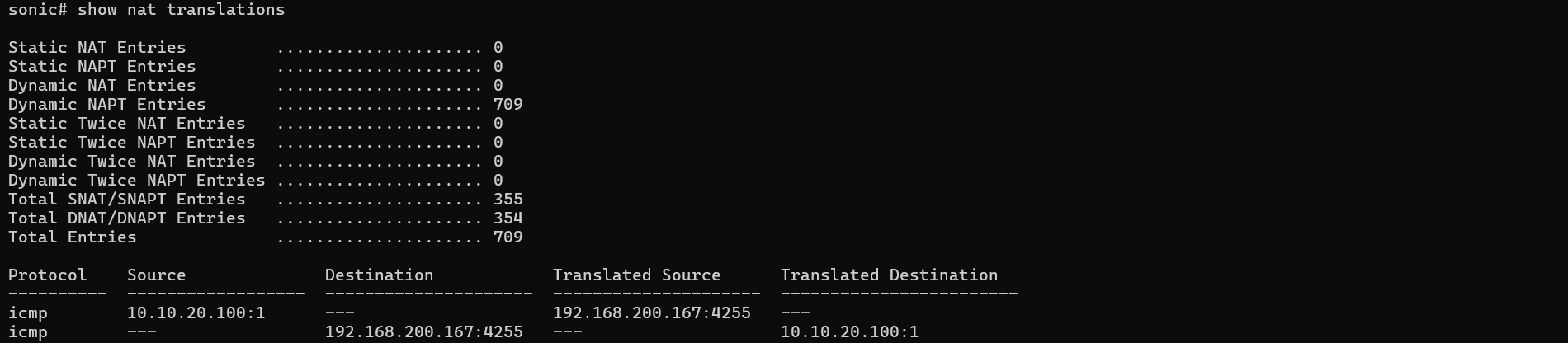
On your AsterNOS VM, check the NAT table again: show nat translations.
Expected Result: You will see new entries showing 10.10.20.100 being translated to 192.168.200.167.
Conclusion
Section titled “Conclusion”This guide has demonstrated that AsterNOS-VPP is a powerful, high-performance, and flexible NAT gateway solution. The completed experiments verify that AsterNOS-VPP provides the essential capabilities required for complex enterprise and service provider edge scenarios.