
Interface Management Configuration Guide
Ethernet Interface Configuration
Section titled “Ethernet Interface Configuration”Introduction
Section titled “Introduction”Ethernet interfaces are commonly used for carrying out business-related tasks and data transmission. They are often referred to as ports.
Numbering Scheme
Section titled “Numbering Scheme”The numbering scheme for Ethernet interfaces in this product series is as follows: EthernetX. Here, X represents the interface number, starting from 1 and increasing incrementally.
Default Configuration of Interfaces
Section titled “Default Configuration of Interfaces”| Parameter | Default value |
|---|---|
| Interface management status | UP |
| Interface FEC (Forward Error Correction) | Disabled |
| Interface description | N/A |
| Interface MTU (Maximum Transmission Unit) | 9100 bytes |
| Interface POE (Power over Ethernet) supply | Disabled |
| Interface LLDP (Link Layer Discovery Protocol) function | Disabled |
| Interface MAC address | Same as device MAC address |
Basic Configuration of Interfaces
Section titled “Basic Configuration of Interfaces”The product series supports interface speeds of 1G, 2.5G, and 10G.
| Operation | Command | Description |
|---|---|---|
| Enter the system configuration view | configure | |
| Enter the interface view | interface Ethernet ID | |
| Set interface description | description String | |
| Set interface speed | speed {1000|2500|10000} | Different types of interfaces support different configuration parameters. Please execute the speed ? command in the relevant interface view to view specific options. |
| Enable interface | no shutdown | By default, the Ethernet interface is on. Execute the “shutdown” command to close the interface business function and set the physical state of the interface to “down” at the same time. Note: The power supply of the POE power interface is not affected by this command. |
| Modify interface FEC mode | fec {rs|fc} | By default, the FEC mode is disabled. The FEC mode must be consistent at both ends of the link for the interface to come up. Use the no fec command to disable the FEC mode for the interface. |
| Enable interface POE supply function | poe enable | By default, the POE supply function for the interface is disabled. Use the no poe enable command to disable the POE supply for the interface |
Configuring Layer 2/3 Mode Switching for Ethernet Interfaces
Section titled “Configuring Layer 2/3 Mode Switching for Ethernet Interfaces”By default, the device’s interfaces do not belong to any VLAN and have no IP address configured. When an interface is configured with an IP address, VRF, or other Layer 3 attributes, it automatically switches to Layer 3 mode. If you need to change the Layer 2/3 mode of an interface, you should first remove the Layer 3 attribute configurations from the interface. Afterward, execute the no router-interface command.
| Operation | Command | Description |
|---|---|---|
| Enter the system configuration view | configure | |
| Enter the interface view | interface Ethernet ID | |
| Switch the interface operation mode to layer 2. | no router-interface |
Maintenance Interface
Section titled “Maintenance Interface”| Operation | Command | Description |
|---|---|---|
| View interface description | show interface description | |
| View interface POE supply information | show interface poe [detail] | |
| View interface status | show interface status | |
| View interface module information | show interface transceiver eeprom dom [ethernet ID] | |
| View interface statistics: | show counters interface [ethernet ID] | |
| Clear interface statistics | clear counters interface |
Port Isolation Configuration
Section titled “Port Isolation Configuration”Introduction
Section titled “Introduction”Port isolation allows the isolation of ports within the same VLAN. By adding ports to an isolation group, isolation between Layer 2 data packets and multicast packets can be achieved for the ports within the isolation group. Traffic between ports within the isolation group and ports not added to the isolation group is not affected by the isolation group and can flow bidirectionally.
Configuring Port Isolation Groups
Section titled “Configuring Port Isolation Groups”| Operation | Command | Description |
|---|---|---|
| Enter the system configuration view | configure | |
| Create and enter isolation group view | port-isolate-group ID | |
| Enter interface view | interface ethernet ID | |
| Add interface to isolation group | port-isolate ID |
Configuration Example
Section titled “Configuration Example”A cell has multiple users, and now requires that the users cannot interoperate with each other’s Layer 2 messages, but all can access the external network.
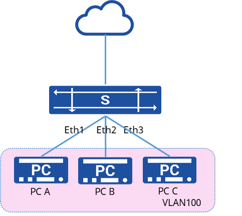
1.Create a VLAN and add the interface to the VLAN
sonic(config)# vlan 100sonic(config)# port-group ethernet 1-4sonic(config-port-group-1-4)# switchport access vlan 1002.Create port isolation group
sonic(config)# port-isolate-group 1sonic(config-port-isolate-group-1)# interface 1,2,31.View the port ioslation group configuration
sonic# show port-isolate-group+------------+-------------+--------+| Group ID | Interface | Mode |+============+=============+========+| 1 | Ethernet1 | L2 || | Ethernet2 | || | Ethernet3 | |+------------+-------------+--------+2.No interoperability between PCs, all PCs can access the external network
Interface Bulk Configuration
Section titled “Interface Bulk Configuration”Introduction
Section titled “Introduction”When configuring a specific function (e.g., port shutdown) across multiple interfaces, individually entering each interface’s view and executing commands can become cumbersome. To simplify this process, the interface bulk configuration feature can be utilized to configure interfaces in batches, thereby reducing the configuration workload.
There is no upper limit to the number of interfaces that can be included in a bulk configuration, only constrained by system resources. However, if a significant number of interfaces are involved, executing commands within the bulk interface configuration view might take longer. When performing bulk interface configuration, if the interfaces listed already possess existing configurations, attempting to enter the bulk configuration view will result in failure. In such cases, the interface list needs to be reselected.
Once inside the bulk interface configuration view, you can utilize the ”?” command to explore the supported command lines for bulk configuration.
Interface Bulk Configuration
Section titled “Interface Bulk Configuration”| Operation | Command | Description |
|---|---|---|
| Enter the system configuration view | configure | |
| Enter the interface group configuration view | port-group ethernet ID-ID | This command only supports interfaces with consecutive ID numbers for bulk configuration |
| Enter the lag group configuration view | port-group lag ID-ID | This command only supports lags with consecutive ID numbers for bulk configuration |
Loopback Interface Configuration
Section titled “Loopback Interface Configuration”Introduction
Section titled “Introduction”The Loopback interface is a type of virtual interface. Once created, the physical layer of the Loopback interface remains in an “up” state unless manually disabled. Due to this characteristic, the Loopback interface can be applied in the following scenarios:
- Source Address for Device-generated IP Packets: Because the Loopback interface address is stable and a unicast address, it is often regarded as an identifier for the device. By allowing or prohibiting packets carrying the Loopback interface address to pass through authentication or security servers, it is possible to permit or restrict packets generated by specific devices. This simplifies packet filtering rules. However, it should be noted that when using the Loopback interface address as the source address for IP packets, routing configurations are needed to ensure the reachability of the Loopback interface to the destination route.
- Dynamic Routing Protocols: In certain dynamic routing protocols, when a router ID is not configured, the Loopback interface’s IP address is used as the router ID by default. In the context of the BGP protocol, to ensure that BGP sessions are not affected by physical interface failures, the source interface for transmitting BGP packets can be configured as the Loopback interface.
- In-band Device Management: The loopback interface can be utilized for device management within the network infrastructure.
Loopback Interface Configuration
Section titled “Loopback Interface Configuration”| Operation | Command | Description |
|---|---|---|
| Enter the system configuration view | configure | |
| Enter the loopback interface configuration view | interface loopback ID | |
| Configure the loopback interface | ip address ip-address | The IP address of the Loopback interface can only be modified and cannot be deleted |