
MC-LAG Configuration Guide
Introduction
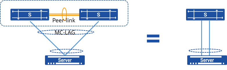
Section titled “Introduction”MC-LAG (Multi Chassis Link Aggregation Group) is a mechanism for achieving link aggregation across devices. It involves aggregating links between one device and two other devices, combining the benefits of regular link aggregation while providing device-level redundancy.
MC-LAG introduces a form of horizontal virtualization, where two physical devices are virtualized as a single logical device. This virtual “single device” is used to perform “one-to-one” link aggregation with the connected upstream or downstream devices.
The following information is synchronized between MC-LAG peers:
- System information
Ensures synchronization of MAC addresses for MC-LAG member ports, enabling the “system ID” field in LACP (Link Aggregation Control Protocol) messages sent to the server to be the same, achieving cross-device link aggregation.
- MC-LAG member port configuration information:
Records details like names of local and remote MC-LAG member ports for consistency checks.
- MC-LAG member port status information
Keeps track of the status of local and remote MC-LAG member ports to ensure isolation between the peer-link and MC-LAG member ports in fault-free scenarios, and to release isolation between the peer-link and the same-named port on the remote side in case of a failure in the remote MC-LAG member port.
- ARP (Address Resolution Protocol) information
ARP entries related to MC-LAG member ports are synchronized between MC-LAG peers.
- FDB (Forwarding Database) information:
FDB entries associated with MC-LAG member ports are synchronized between MC-LAG peers.
Explanation of Principles
Section titled “Explanation of Principles”As shown in the diagram, on two separate devices, a cross-device link aggregation group is established and connected to ordinary link aggregation ports on the user side. Once the MC-LAG is established, entries can be synchronized between devices. The direct link between Device1 and Device2 serves as the peer-link interface, used for protocol messages and forwarding traffic during failures. The links connecting the devices to users, acting as member interfaces of the MC-LAG, handle incoming traffic, distribute loads, and provide backup protection for the links.
In the context of MC-LAG, SONiC employs a lightweight Inter-Chassis Communication Protocol (ICCP) on the control plane, conducting only a limited amount of consistency checks and information synchronization while ensuring the functionality.
ICCP, defined in RFC7275, serves as the standard protocol for inter-chassis communication. In the MC-LAG implementation, the ICCP protocol establishes connections between MC-LAG peer devices using TCP port 8888. This streamlined ICCP protocol primarily focuses on configuring consistency checks and synchronizing ARP and MAC table entries.
Between the two MC-LAG peer devices, the local_ip and peer_ip addresses are used as the source and destination addresses for establishing the TCP connection to form the ICCP neighbor relationship. Once the ICCP connection is successfully established, the system sends heartbeat messages to the peer every 1 second. If no heartbeat messages are received for 15 consecutive intervals, the connection is deemed timed out, leading to the termination of the ICCP connection.
MC-LAG Loop Prevention Mechanism
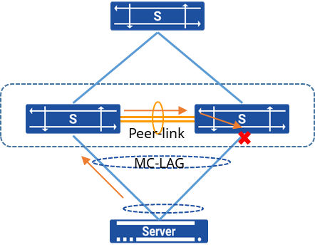
Section titled “MC-LAG Loop Prevention Mechanism”MC-LAG itself comes with a loop prevention mechanism, as shown in the diagram. When a device receives a broadcast packet from the MC-LAG side, this broadcast packet is transmitted through the Peer-link link to the opposite device. Due to the flow isolation between the peer-link link and the MC-LAG member interfaces, any traffic coming in from the peer-link port will not be forwarded out through the MC-LAG member interfaces. This effectively prevents the formation of loops.
MC-LAG Fault Handling
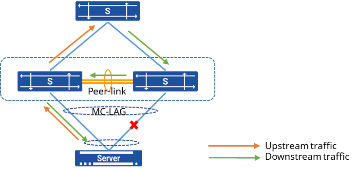
Section titled “MC-LAG Fault Handling”As illustrated in the diagram, in the event of a link failure on the MC-LAG side, the device will proactively update the interface information for the corresponding terminal’s MAC table entries and ARP table entries to reflect the peer-link interface. Consequently, downstream traffic will be forwarded through the peer-link interface to the other device, ensuring seamless fault handling for the user. Once the fault is rectified, and the MC-LAG interface is back up, traffic will resume its normal forwarding behavior.
MC-LAG Configuration
Section titled “MC-LAG Configuration”| Operation | Command | Description |
|---|---|---|
| Enter the system configuration view | configure terminal | |
| Enter the link-aggregation configuration view and create a link-aggregation group | interface link-aggregation lag-id | Only supported single domain |
| the range of 1 to 4095. | ||
| Create a MC-LAG domain | mclag domain domain-id | |
| Delete a MC-LAG domain | no mclag domain domain-id | |
| Configure peerlink interface | peer-link {ethernet|link-aggregation} name | |
| Configure the peer IP address for the MC-LAG control link | peer-address A.B.C.D | |
| Set the local IP address for the MC-LAG control link | local-address A.B.C.D | |
| Add a member lag port to the MC-LAG group | member lag lag-id | |
| Remove a member lag port from the MC-LAG group | no member lag lag-id | |
| Enter the configuration view for a VLAN interface | interface vlan vlan-id | |
| Modify the MAC address of a VLAN interface | mac_address HH:HH:HH:HH:HH:HH | |
| Configure dad to detect errdown delay time | dad detection-delay time | time: Delay time, range 0-512 |
| Configure dad detection and recovery delay time | dad recovery-delay {mlag|non-mlag} time | time: Delay time, range 0-512 |
| Configure the VRF where the dad link is located | dad vrf {default|string} | string:Specify VRF name |
| Configure the management port for dad detection | dad mgmt-interface interface_name | interface_name:The port name, such as Ethernet1, can be configured to prevent the backup device port errdown from simultaneously shutting down the IP port of the configuration management port, resulting in the device being unable to connect. |
Configuration Example
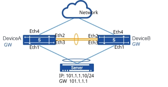
Section titled “Configuration Example”Network requirements
A server is dual-homed to an Ethernet network through M-LAG. The customer requires high service reliability. Link aggregation between the server and devices only achieves link-level reliability, and a fault on a device may cause service interruption. M-LAG can be configured. When devices work properly, links load balance traffic and a fault of any device does not affect services. High service reliability is therefore ensured.

Procedure
1.Create an aggregation port and add the physical interfaces connected to Server and Device C to the aggregation port group
# Device A
sonic(config)# interface link-aggregation 1sonic(config)# interface ethernet 1sonic(config-if-1)# link-aggregation-group 1# Device B
sonic(config)# interface link-aggregation 1sonic(config)# interface ethernet 1sonic(config-if-1)# link-aggregation-group 12.Create an aggregation port and add the interconnection port between Device A and Device B to the aggregation group as the peerlink interface
# Device A
sonic(config)# interface link-aggregation 2sonic(config)# interface ethernet 2sonic(config-if-2)# link-aggregation-group 2sonic(config)# interface ethernet 3sonic(config-if-3)# link-aggregation-group 2# Device B
sonic(config)# interface link-aggregation 2sonic(config)# interface ethernet 2sonic(config-if-2)# link-aggregation-group 2sonic(config)# interface ethernet 3sonic(config-if-3)# link-aggregation-group 23.Create VLAN100 to add all aggregation ports to VLAN
# Device A
sonic(config)# vlan 100sonic(config)# interface link-aggregation 1sonic(config-lagif-1)# switchport access vlan 100sonic(config)# interface link-aggregation 2sonic(config-lagif-2)# switchport access vlan 100sonic(config)# interface vlan 100sonic(config-vlanif-100)# ip address 101.1.1.1/24sonic(config-vlanif-100)# mac-address 00:00:00:11:22:10# Device B
sonic(config)# vlan 100sonic(config)# interface link-aggregation 1sonic(config-lagif-1)# switchport access vlan 100sonic(config)# interface link-aggregation 2sonic(config-lagif-2)# switchport access vlan 100sonic(config)# interface vlan 100sonic(config-vlanif-100)# ip address 101.1.1.1/24sonic(config-vlanif-100)# mac-address 00:00:00:11:22:104.Create VLAN200 and configure the IP address to add the peerlink interface to the VLAN
# Device A
sonic(config)# vlan 200sonic(config)# interface link-aggregation 2sonic(config-lagif-2)# switchport trunk vlan 200sonic(config-lagif-2)# switchport trunk vlan 100sonic(config)# interface vlan 200sonic(config-vlanif-200)# ip address 10.1.1.24/24# Device B
sonic(config)# vlan 200sonic(config)# interface link-aggregation 2sonic(config-lagif-3)# switchport trunk vlan 200sonic(config-lagif-2)# switchport trunk vlan 100sonic(config)# interface vlan 200sonic(config-vlanif-200)# ip address 10.1.1.48/245.Create an MC-LAG and specify the member interface, peerlink interface and peerlink port IP address
# Device A
sonic(config)# mclag domain 1sonic(mclag-domain)# local-address 10.1.1.24sonic(mclag-domain)# peer-address 10.1.1.48sonic(mclag-domain)# peer-link lag 2sonic(mclag-domain)# member lag 1# Device B
sonic(config)# mclag domain 1sonic(mclag-domain)# local-address 10.1.1.48sonic(mclag-domain)# peer-address 10.1.1.24sonic(mclag-domain)# peer-link lag 2sonic(mclag-domain)# member lag 1Verify configuration
1.Check MC-LAG status
sonic# show mclag stateThe MCLAG's keepalive is: OKMCLAG info sync is: completedDomain id: 1MCLAG session Channel: Primary channelVRF Name: defaultconsistency Check Action: idleLocal Ip: 10.1.1.48Peer Ip: 10.1.1.24Peer Link Interface: PortChannel0003Keepalive time: 1sesssion Timeout : 15Peer Link Mac: 00:11:24:1a:1b:61Admin Role: NoneRole: StandbyMCLAG Interface: PortChannel0001Loglevel: DEBUG2.The server can ping the gateway and check the MAC address of the device
# Use the Server ping gateway address
Testuser@78:~$ping 101.1.1.1PING 101.1.1.1 (101.1.1.1) 56(84) bytes of data.64 bytes from 101.1.1.1: icmp_seq=1 ttl=64 time=3.38 ms64 bytes from 101.1.1.1: icmp_seq=2 ttl=64 time=1.33 ms64 bytes from 101.1.1.1: icmp_seq=3 ttl=64 time=1.32 ms64 bytes from 101.1.1.1: icmp_seq=4 ttl=64 time=1.29 ms^C--- 101.1.1.1 ping statistics ---4 packets transmitted, 4 received, 0% packet loss, time 3005msrtt min/avg/max/mdev = 1.291/1.835/3.389/0.897 ms# Display the MAC address on Device B device
sonic# show mac-addressNo. Vlan MacAddress Port Type----- ------ ----------------- --------------- -------1 101 00:51:82:11:0F:78 PortChannel0001 Dynamic3.Cut off the link between DeviceB and DeviceC, use the server ping gateway again, and still be able to ping, and check the MAC address of the device at this time
# Use the Server ping gateway address
Testuser@78:~$ping 101.1.1.1PING 101.1.1.1 (101.1.1.1) 56(84) bytes of data.64 bytes from 101.1.1.1: icmp_seq=1 ttl=64 time=3.38 ms64 bytes from 101.1.1.1: icmp_seq=2 ttl=64 time=1.33 ms64 bytes from 101.1.1.1: icmp_seq=3 ttl=64 time=1.32 ms64 bytes from 101.1.1.1: icmp_seq=4 ttl=64 time=1.29 ms^C--- 101.1.1.1 ping statistics ---4 packets transmitted, 4 received, 0% packet loss, time 3005msrtt min/avg/max/mdev = 1.291/1.835/3.389/0.897 ms# Display the MAC address on your Device B device
sonic# show mac-addressNo. Vlan MacAddress Port Type----- ------ ----------------- --------------- -------1 101 00:51:82:11:0F:78 PortChannel0002 DynamicExample of MCLAG network migration scenario
Section titled “Example of MCLAG network migration scenario”Network requirements
The server adopts a dual-homing access method to connect to the standard Ethernet network, utilizing cross-device link aggregation technology to ensure device-level service high availability. During normal operation, the links perform load sharing, and any single device failure will not impact services. Based on the above network configuration, when the enterprise needs to migrate one of the MCLAG devices, it is necessary to configure and save the startup delay time for the peerlink port. This prevents potential loops from occurring when the device rejoins the MCLAG network before the MCLAG is fully established, thereby ensuring network stability.
Procedure
# Device A
sonic(config)# interface link-aggregation 1sonic(config)# interface ethernet 1sonic(config-if-1)# link-aggregation-group 1sonic(config)# interface link-aggregation 2sonic(config)# interface ethernet 2sonic(config-if-2)# link-aggregation-group 2sonic(config)# interface ethernet 3sonic(config-if-3)# link-aggregation-group 2sonic(config)# vlan 100sonic(config)# interface link-aggregation 1sonic(config-lagif-1)# switchport access vlan 100sonic(config)# interface link-aggregation 2sonic(config-lagif-2)# switchport access vlan 100sonic(config)# interface vlan 100sonic(config-vlanif-100)# ip address 101.1.1.1/24sonic(config-vlanif-100)# mac-address 00:00:00:11:22:10sonic(config)# vlan 200sonic(config)# interface link-aggregation 2sonic(config-lagif-2)# switchport trunk vlan 200sonic(config-lagif-2)# switchport trunk vlan 100sonic(config)# interface vlan 200sonic(config-vlanif-200)# ip address 10.1.1.24/24sonic(config)# mclag domain 1sonic(mclag-domain)# local-address 10.1.1.24sonic(mclag-domain)# peer-address 10.1.1.48sonic(mclag-domain)# peer-link lag 2sonic(mclag-domain)# member lag 1sonic(config)# interface ethernet 2sonic(config-if-2)# startup-delay 120sonic(config-if-2)# interface ethernet 3sonic(config-if-3)# startup-delay 120sonic# writesave running-config...Existing files will be overwritten, continue? [y/N]: yRunning command: /usr/local/bin/sonic-cfggen -d --print-data > /etc/sonic/config_db.json# Device B
sonic(config)# interface link-aggregation 1sonic(config)# interface ethernet 1sonic(config-if-1)# link-aggregation-group 1sonic(config)# interface link-aggregation 2sonic(config)# interface ethernet 2sonic(config-if-2)# link-aggregation-group 2sonic(config)# interface ethernet 3sonic(config-if-3)# link-aggregation-group 2sonic(config)# vlan 100sonic(config)# interface link-aggregation 1sonic(config-lagif-1)# switchport access vlan 100sonic(config)# interface link-aggregation 2sonic(config-lagif-2)# switchport access vlan 100sonic(config)# interface vlan 100sonic(config-vlanif-100)# ip address 101.1.1.1/24sonic(config-vlanif-100)# mac-address 00:00:00:11:22:10sonic(config)# vlan 200sonic(config)# interface link-aggregation 2sonic(config-lagif-2)# switchport trunk vlan 200sonic(config-lagif-2)# switchport trunk vlan 100sonic(config)# interface vlan 200sonic(config-vlanif-200)# ip address 10.1.1.48/24sonic(config)# mclag domain 1sonic(mclag-domain)# local-address 10.1.1.48sonic(mclag-domain)# peer-address 10.1.1.24sonic(mclag-domain)# peer-link lag 2sonic(mclag-domain)# member lag 1sonic(config)# interface ethernet 2sonic(config-if-2)# startup-delay 120sonic(config-if-2)# interface ethernet 3sonic(config-if-3)# startup-delay 120sonic# write save running-config... Existing files will be overwritten, continue? [y/N]: yRunning command: /usr/local/bin/sonic-cfggen -d --print-data > /etc/sonic/config_db.jsonThis configuration ensures that when devices in the network undergo migration or encounter failures, MCLAG can still be properly established after reboot, thereby preventing loop storms.