
QoS Configuration Guide
Introduction
Section titled “Introduction”QoS (Quality of Service) is a technology that addresses issues such as network latency and congestion. As a security mechanism in the network, QoS can provide better service capabilities to improve service quality. In normal circumstances, if the network is only used for specific time-insensitive applications, such as web applications or email setups, QoS may not be necessary. However, for critical applications and multimedia applications, QoS becomes particularly important. During network overload or congestion, QoS ensures that important business traffic is not affected by delays or losses while ensuring the efficient operation of the network.
Explanation of Principles
Section titled “Explanation of Principles”Priority Mapping
Section titled “Priority Mapping”Networks typically face various types of traffic, each with different performance and service requirements. Therefore, to meet the needs of different applications and services and ensure the performance of critical applications while improving the overall network performance, users can use different QoS priorities in different networks. This involves mapping the priority carried by the packet to the local priority processed by the device, providing differentiated QoS services based on the local priority.
The priority carried by the packet is called packet priority, for example: VLAN packets use 802.1p, and IP packets use DSCP.
The local priority, also known as TC (traffic class), corresponds to the eight queues at the egress by default. Differentiated services for packets of different priorities are implemented based on the scheduling methods of different egress queues.
Queue Scheduling
Section titled “Queue Scheduling”Queue scheduling algorithms are one of the core mechanisms for implementing network QoS control and an important part of network resource management. It controls the use of link bandwidth by different types of packets to provide different levels of service to different data streams.
Each interface of the device in the outbound direction is configured with 8 queues. They are identified by queue IDs from 0 to 7. Packets are assigned to different egress queues based on the mapping from local priority to egress queues, and then processed according to the configured queue scheduling method.
- Strict Scheduling
Strict priority scheduling. The scheduling is strictly based on the priority of the egress queue, and only when the high-priority queue is empty will the low-priority queue be scheduled. Users can put high-priority business packets into high-priority queues and non-critical business packets into low-priority queues to ensure that high-priority business can be scheduled first during congestion, ensuring business stability. The priority scheduling order for queues is: Queue7> Queue6> Queue5> Queue4> Queue3> Queue2> Queue1> Queue0. It is worth noting that this scheduling method may cause packets in low-priority queues to be scheduled late, leading to queue starvation.
- DWRR Scheduling
Weighted Round Robin scheduling. Queues are scheduled in a round-robin manner according to their weights. The device supports a mixed scheduling mode of STRICT and DWRR for different queues under the same interface. Queues configured with STRICT scheduling mode are given priority. When there are no packets in queues scheduled by the STRICT mode, queues are scheduled according to the weights in the DWRR mode. By default, the scheduling mode for queues is DWRR, with a weight of 100 for each queue.
Traffic Shaping
Section titled “Traffic Shaping”When the transmission rate of packets exceeds the reception rate, or when the downstream device interface speed is lower than that of the upstream device, it can lead to network congestion. Without restricting the size of user-generated traffic, a continuous burst of business data from numerous users can further congest the network. To ensure that limited network resources are effectively utilized to serve users, it’s necessary to impose limits on user-generated traffic. Typically, traffic specifications are evaluated using token buckets.
A token bucket can be envisioned as a container that holds a certain number of tokens. The device deposits tokens into the bucket at a predetermined rate. When the bucket is full, any excess tokens overflow, and no more tokens are added to the bucket. The token bucket is merely a method for measuring traffic and does not filter or take any action on the traffic, such as discarding packets; these operations are performed by other functionalities.
QoS Priority Configuration
Section titled “QoS Priority Configuration”| Configure Tasks | Instructions | Index |
|---|---|---|
| Configure priority mapping relationship | Required | Configuring Priority Mapping Relationship |
| Bind priority mapping relationship | Required | Binding Priority Mapping Relationship |
Configuring Priority Mapping Relationship
Section titled “Configuring Priority Mapping Relationship”By default, the mapping from the DSCP/802.1p priority carried in the packet to the local priority is as follows: all mapped to priority 0. The mapping from local priority to the egress queue is as follows: tc 0—queue 0, tc 1—queue 1, tc 2—queue 2, tc 3—queue 3, tc 4—queue 4, tc 5—queue 5, tc 6—queue 6, tc 7—queue 7.
| Operation | Command | Description |
|---|---|---|
| Enter the system configuration view | configure terminal | |
| Configure priority mapping relationship | qos map {dot1p_to_tc|dscp_to_t c|tc_to_queue} <profile_name> <in_value> <value> | dot1p_to_tc: Mapping from 802.1p priority to local priority. dscp_to_tc: Mapping from DSCP priority to local priority. tc_to_queue: Mapping from local priority to egress queue. in_value: Input priority (priority carried in the packet). value: Local priority. |
Binding Priority Mapping Relationship
Section titled “Binding Priority Mapping Relationship”| Operation | Command | Description |
|---|---|---|
| Enter the system configuration view | configure terminal | |
| Bind the specified mapping relationship between local priority and queue globally | qos-map-all bind tc_to_queue <profile name> | |
| Enter the interface view | interface ethernet <ID> | |
| Bind the QoS map to the specified interface | qos-map bind <type> <profile_name> | type: QoS map type, which includes dot1p_to_tc and dscp_to_tc |
QoS Queue Scheduling Configuration
Section titled “QoS Queue Scheduling Configuration”The device supports a hybrid scheduling mode of STRICT and DWRR for different queues under the same interface. Queues configured with STRICT mode for priority scheduling are given priority, and when there are no packets in the STRICT mode queues, DWRR queues are scheduled according to their weights. By default, the scheduling mode for queues is DWRR, with weights all set to 1.
| Operation | Command | Description |
|---|---|---|
| Enter the interface configuration view | interface ethernet<interface_num> | |
| Configure the queue scheduling mode for the interface | uc-tx-queue scheduler <queue_id > mode STRICT uc-tx-queue scheduler <queue_id > mode DWRR [weight <value>] |
Traffic Shaping Configuration
Section titled “Traffic Shaping Configuration”| Configure Tasks | Instructions | Index |
|---|---|---|
| Configure traffic shaping based on the interface | Optional | Configuring Traffic Shaping Based on Interface |
| Configure queue rate limiting | Required | Configuring Queue Rate Limiting |
| Configure traffic shaping based on flows | Required | Configuring Traffic Shaping Based on Flows |
Configuring Traffic Shaping Based on Interface
Section titled “Configuring Traffic Shaping Based on Interface”| Operation | Command | Description |
|---|---|---|
| Enter the interface configuration view | interface ethernet<interface_num> | |
| Traffic Shaping Configuration Based on Interface | port-shaper enable <pir> <pbs> | The PIR unit is bytes per second (byte/s). The PBS unit is bytes. Traffic shaping can be directly configured based on the interface, and it takes effect in the outbound direction of the interface. |
Configuring Queue Rate Limiting
Section titled “Configuring Queue Rate Limiting”| Operation | Command | Description |
|---|---|---|
| Enter the interface configuration view | interface ethernet<interface_num> | |
| Configure queue rate limiting | uc-tx-queue scheduler <queue_id> {<pir>|<pbs>} | pir pbs |
Configuring Traffic Shaping Based on Flows
Section titled “Configuring Traffic Shaping Based on Flows”| Configure Tasks | Instructions | Index |
|---|---|---|
| Create a traffic behavior | Required | |
| Configure a CAR (Committed Access Rate) template | Required | |
| Bind the traffic behavior to the interface | Required |
Creating a Traffic Behavior
Section titled “Creating a Traffic Behavior”| Operation | Command | Description |
|---|---|---|
| Enter the system configuration view | configure terminal | |
| Create a traffic behavio | traffic-behavior <traffic-behavior-name> |
Configuring a CAR Template
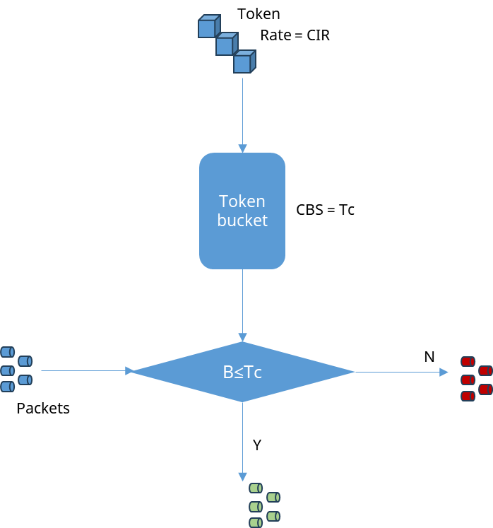
Section titled “Configuring a CAR Template”Single bucket single rate (SBSR) mode is a traffic control mechanism that uses a token bucket to regulate the forwarding rate of packets, aiming to control the average rate of traffic to ensure that the traffic on the network does not exceed a specific rate limit. When evaluating traffic, the parameters of the token bucket include:
- CIR (Committed Information Rate): The rate at which tokens are added to the token bucket, default unit is KBps.
- CBS (Committed Burst Size): The capacity of the token bucket, default unit is bytes, representing the size of the burst that can be accommodated by the token bucket.
In single bucket single rate mode, when the device receives a packet, it compares the number of tokens in the bucket. If there are enough tokens, the packet is forwarded. If there are not enough tokens, the packet is either dropped or buffered. Let Tc represent the number of tokens in the bucket, and Tc is initialized to CBS.
- If the length of the packet does not exceed the number of tokens Tc in the bucket, the packet is marked as green, and Tc is decremented by the size of the packet (Tc = Tc - B).
- If the length of the packet exceeds the number of tokens Tc in the bucket, the packet is marked as red, and Tc remains unchanged.
Dual token bucket dual rate (TBDR) mode uses two token buckets to control packet transmission, each defining the “CBS (Committed Burst Size)” and “PBS (Peak Burst Size)” respectively.
- CIR: Committed Information Rate, expressed in default units of KBps, represents the rate at which tokens are added to the C bucket.
- CBS: Committed Burst Size, expressed in default units of bytes, represents the maximum amount of data that can be transmitted from the C bucket.
- PIR: Peak Information Rate, expressed in default units of KBps, represents the rate at which tokens are added to the P bucket. PIR is greater than CIR.
- PBS: Peak Burst Size, expressed in default units of bytes, represents the maximum amount of data that can be transmitted from the P bucket.
Token addition method: Tokens are added to the C and P buckets at rates of CIR and PIR respectively. Since these two token buckets are independent, if one bucket runs out of tokens, incoming packets to that bucket will be discarded while the other bucket remains unaffected and continues to receive tokens. Tc and Tp represent the token counts in the C and P buckets respectively, with both initialized to CBS and PBS.
- If the length of the packet exceeds the token count in the P bucket (Tp), the packet is marked as red, and Tc and Tp remain unchanged.
- If the length of the packet is greater than Tc but less than Tp, the packet is marked as yellow, and Tp is decreased by the token count (B) while Tc remains unchanged.
- If the length of the packet does not exceed the token count in the C bucket (Tc), the packet is marked as green, and both Tp and Tc are decreased by the token count (B).
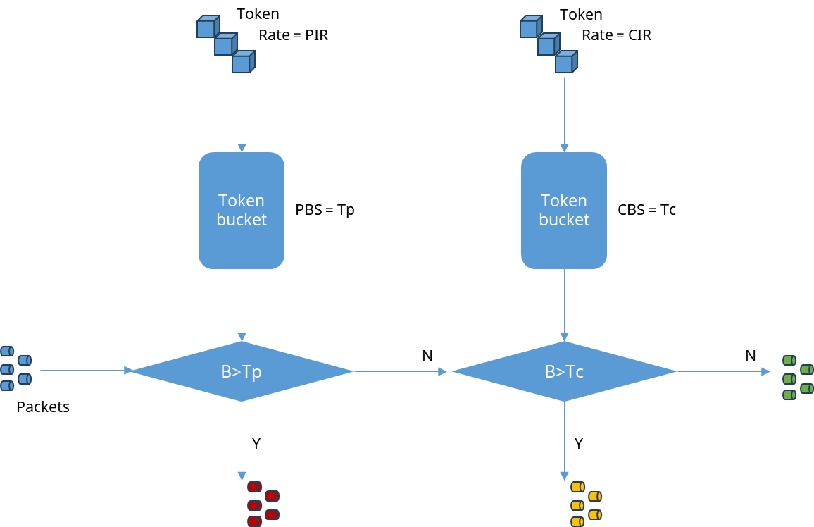
The Dual Token Bucket Dual Rate (TBDR) mode allows for more granular control over different types of traffic, enabling marking and management based on rate requirements and congestion conditions. It facilitates the implementation of more sophisticated QoS policies to ensure that different traffic classes receive appropriate treatment, thereby maintaining network stability and service quality.
| Operation | Command | Description |
|---|---|---|
| Enter Traffic behavior configuration view | traffic-behavior | |
| Configure CAR template | car {sr-tcm|tr-tcm} [meter-type {bytes|packets}] cir <cir> [cbs <cbs>] [pir <pir>] [pbs <pbs>] [yellow-packet-action {DROP|FORWARD|REMARK}][red-packet-action {DROP|FORWARD|REMARK}] [remark-dot1p <value>][remark-dscp <value>] [remark-tc <value>] | cir: Committed Information Rate, which represents the guaranteed rate of traffic that can pass through. cbs: Committed Burst Size, indicating the amount of committed burst traffic that can be passed through instantly. pir: Peak Information Rate, which represents the maximum rate of traffic that can pass through. pbs: Peak Burst Size, indicating the amount of peak burst traffic that can be passed through instantly. |
Binding Traffic Behavior
Section titled “Binding Traffic Behavior”By configuring a CAR (Committed Access Rate) template and binding it with an ACL (Access Control List), users can finely control which traffic needs to be rate-limited. This approach helps in managing bandwidth usage for specific types or sources of traffic, preventing certain flows from excessively consuming network resources and thereby balancing the overall network utilization.
| Operation | Command | Description |
|---|---|---|
| Enter ACL configuration view | access-list L3 name egress | |
| Bind the CAR template with the ACL | rule id traffic-behavior traffic-behavior-name | |
| Enter interface configuration view | interface ethernet interface-id | |
| Bind the behavior to the interface | acl name |
It is also possible to bind the CAR template directly to the port.
| Operation | Command | Description |
|---|---|---|
| Enter interface configuration view | interface ethernet interface-id | |
| Bind the behavior to the interface | traffic-behavior bind [egress] traffic-behavior-name | egress:bind in the direction of the output interface |
Display and Maintenance
Section titled “Display and Maintenance”| Operation | Command |
|---|---|
| View QoS map configuration | show qos map{all|dot1p_to_tc |dscp_to_tc|tc_to_queue} |
| View the interface mapping table | show interface qos-map-bind |
| View outbound queue statistics | show queue counters [<interface-name>] |
| View interface queue scheduling mode | show interface uc-tx-queue |
| View interface-based traffic shaping rules | show interface port-shaper |
| View configured behaviors and CAR policies | show traffic-behavior rule |
| View behavior hit statistics | show traffic-behavior counters |
Priority Mapping and Queue Scheduling Configuration Example
Section titled “Priority Mapping and Queue Scheduling Configuration Example”Network Requirement
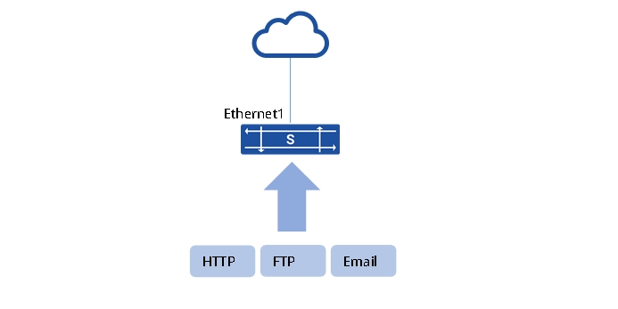
In a certain data center network structure as shown in the diagram below, there are three types of traffic accessing the Internet: HTTP, FTP, and Email, with corresponding DSCP values of 33, 35, and 27.
The current requirement is to configure the packet transmission priorities on the device as follows: HTTP > FTP > Email. In case of congestion, ensure the priority transmission of HTTP packets. HTTP data must be transmitted first before sending other data, and the ratio of FTP to Email traffic should be controlled at 2:1.
Procedure
1.Assign IP Addresses to Interfaces for Network Access
2.Configure DSCP-to-Priority Mapping
sonic(config)# qos map dscp_to_tc profile1 33 4sonic(config)# qos map dscp_to_tc profile1 35 3sonic(config)# qos map dscp_to_tc profile1 27 2sonic(config)# interface ethernet 1sonic(config-if-1)# qos-map bind dscp_to_tc profile13.Configure mapping from local priority to egress queue
sonic(config)# qos map tc_to_queue test 0 0sonic(config)# qos map tc_to_queue test 1 1sonic(config)# qos map tc_to_queue test 2 2sonic(config)# qos map tc_to_queue test 3 3sonic(config)# qos map tc_to_queue test 4 4sonic(config)# qos map tc_to_queue test 5 5sonic(config)# qos map tc_to_queue test 6 6sonic(config)# qos map tc_to_queue test 7 7sonic(config)# qos-map-all bind tc_to_queue4.Configure DWRR Scheduling on Ethernet1
sonic(config)# interface ethernet 1sonic(config-if-1)# uc-tx-queue scheduler 4 mode STRICTsonic(config-if-1)# uc-tx-queue scheduler 3 mode DWRR weight 2sonic(config-if-1)# uc-tx-queue scheduler 2 mode DWRR weight 1Verify configuration
1.View configuration
sonic# show qos map dscp_to_tc{"profile1":{"27":"2","33":"4","35":"3"}}sonic# show interface qos-map-bind{"Ethernet1":{"dscp_to_tc_map":"[DSCP_TO_TC_MAP|profile1]"}}sonic# show interface uc-tx-queue{"Ethernet1|4":{"SCHEDULER|scheduler.Ethernet1_2":{"type":"STRICT"}}"Ethernet1|3":{"SCHEDULER|scheduler.Ethernet1_3":{"type":"DWRR"}}"Ethernet1|2":{"SCHEDULER|scheduler.Ethernet1_4":{"type":"DWRR"}}}When congestion occurs, queue4 should be prioritized, and there should be no packet drops in queue4. This means that the packets from the HTTP traffic (DSCP 33) in queue4 should be serviced without any drops.
Traffic Shaping Configuration Example
Section titled “Traffic Shaping Configuration Example”Network requirements
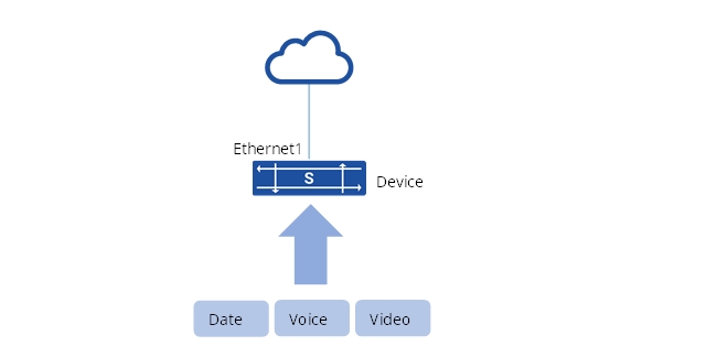
A data center network structure is shown below, the services from the network side of the network are data, voice and video, carrying 802.1p priorities of 2, 3 and 4 respectively.
Bandwidth jitter may occur because the traffic rate on the ingress side of the Device is greater than the rate on the egress side. To reduce bandwidth jitter while ensuring bandwidth requirements for various services, it is required that:
- Device egress bandwidth is limited to 1000Mbit/s;
- Data bandwidth limited to 200Mbit/s;
- Voice bandwidth is limited to 300Mbit/s;
- Video bandwidth limited to 500Mbit/s;
Procedure
1.Configure each interface IP to enable users to access the network through the Device.
2.Configure priority mapping for dot1p_to_tc.
sonic(config)# qos map dot1p_to_tc profile1 2 2sonic(config)# qos map dot1p_to_tc profile1 3 3sonic(config)# qos map dot1p_to_tc profile1 4 4sonic(config)# interface ethernet 1sonic(config-if-1)# qos-map bind dot1p_to_tc profile13.Configure port traffic shaping on Ethernet1 of the Device, set pir=12500000 byte/s, pbs=1280000 byte.
sonic(config)# interface ethernet 1sonic(config-if-1)# port-shaper enable 12500000 12800004.Configure queue traffic shaping policies.
sonic(config)# interface ethernet 1sonic(config-if-1)# uc-tx-queue scheduler 2 mode STRICTsonic(config-if-1)# uc-tx-queue scheduler 2 pir 200000000sonic(config-if-1)# uc-tx-queue scheduler 3 mode STRICTsonic(config-if-1)# uc-tx-queue scheduler 3 pir 300000000sonic(config-if-1)# uc-tx-queue scheduler 4 mode STRICTsonic(config-if-1)# uc-tx-queue scheduler 4 pir 500000000Verify configuration
1.Configuration Verification
sonic# show qos map dot1p_to_tcsonic# show interface qos_map_bindsonic# show interface port-shaper2.Streaming verification
After successful configuration, check the port count through the command show interfaces counters and check the queue reception through the command show queue counters 1 on the Device, both meet the requirements.