
IP Multicast Configuration Guide
IP multicast is a method of transmitting data in computer networks that allows a sender to deliver data to multiple receivers simultaneously, rather than being limited to point-to-point or broadcast transmission. A key concept of multicast is the “multicast group,” which is a collection of receivers interested in a specific data stream.
Multicast has the following characteristics in network data transmission:
- Many-to-Many Communication: Multicast enables a sender to send data to a multicast group, and multiple receivers in the multicast group can simultaneously receive the same data stream. This communication mode is suitable for scenarios where multiple devices share the same data, such as real-time video streams, online gaming, etc.
- Bandwidth Efficiency: Unlike broadcasting, multicast transmits only to receivers interested in a specific data stream. This can significantly save network bandwidth because data is only sent to where it is needed, rather than to every node.
- Applicability to Multicast Domains: Multicast can be used within a local area network (LAN) or across a wide area network (WAN). This makes it suitable for communication needs across different geographical locations.
- Multiplexing: In a multicast group, multiple receivers can share the same data. As a result, the sender only needs to send the data once, rather than sending separately to each receiver.
- Use of IGMP and MLD: In IPv4 networks, IGMP (Internet Group Management Protocol) is used to manage multicast group members. In IPv6 networks, MLD (Multicast Listener Discovery) is used to achieve similar functionality.
- Support for Various Applications: Multicast is widely used in various scenarios, including streaming media, video conferencing, online gaming, data synchronization for distributed applications, and more.
In summary, IP multicast is an efficient data transmission method that addresses the many-to-many communication needs in modern networks by delivering data to multiple receivers simultaneously, effectively saving network resources.
Introduction
Section titled “Introduction”By default, when a Layer 2 device receives a multicast data packet, it broadcasts the multicast packet within the VLAN. This not only wastes bandwidth but also poses a security risk. To control this broadcast behavior, you can configure IGMP Snooping on switches to build multicast forwarding entries. Alternatively, you can manually configure interfaces to join specific multicast groups. This allows users on those interfaces to receive multicast data for the specified group in a stable and consistent manner. With this configuration, when a multicast data packet with a destination IP matching the multicast group is received, it will only be forwarded to interfaces within the VLAN that are configured for that multicast IP address.
Explanation of Principles
Section titled “Explanation of Principles”In IGMP, ports have two roles:
- Member Ports: Member ports refer to the switch ports connected to host devices such as computers, routers, etc. These ports listen to IGMP messages sent by hosts to determine which multicast groups the hosts are interested in. Based on this information, the switch can decide which member ports to forward multicast data to.
- Router Ports: Router ports are switch ports connected to routers. Routers are responsible for providing multicast services to multiple subnets in the network. Router ports listen to IGMP messages sent by routers to determine which multicast groups the router is a member of. Switches forward multicast data to these ports so that routers can distribute multicast data across various subnets.
Configuring Static Multicast
Section titled “Configuring Static Multicast”| Operation | Command | Description |
|---|---|---|
| Enter the VLAN view | vlan ID | |
| Enable IGMP Snooping function | igmp-snooping enable | |
| Configure a static router port | igmp-snooping mrouter ethernet interface-name | |
| Configure a static member port | interface l2mc-static-group ethernet interface-name vlan-id ip-address |
Display and Maintenance
Section titled “Display and Maintenance”| Operation | Command | Description |
|---|---|---|
| View IGMP enablement information | show vlan igmp-snooping | |
| Display IGMP Snooping router port information | show vlan igmp-snooping mrouter | |
| View membership information for multicast groups | show l2-multicast-table | |
| Check the aging time for IGMP Snooping router ports | show vlan igmp-snooping mrouter-aging |
Configuration Example
Section titled “Configuration Example”Network requirements
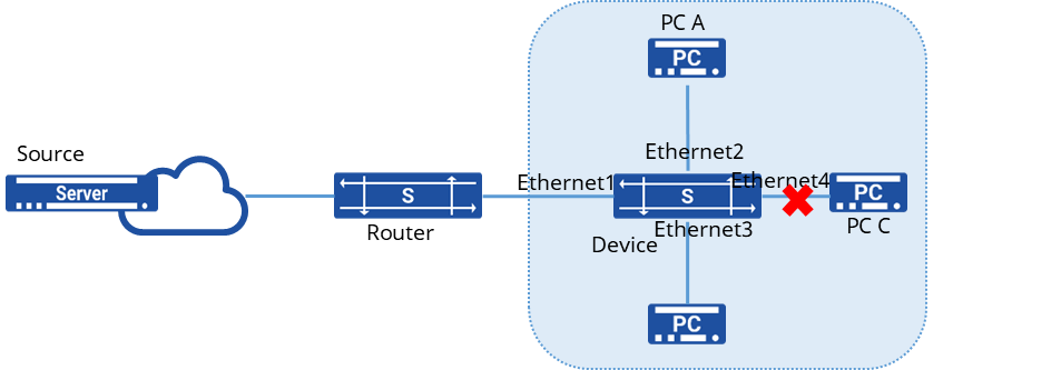
Router through the Device connected to the user network, the network has A, B, C three users, where only two users A and B need to receive multicast data from multicast group 224.1.1.1, C does not need to receive.
Procedure
1.Create a VLAN and add member interfaces
sonic(config)# vlan 100sonic(config)# port-group ethernet 1-4sonic(config-port-group-1-4)# switchport access vlan 1002.Enable IGMP Snooping on the interface and add interfaces Ethernet2, 3 to the multicast group in a static manner
sonic(config)# interface ethernet 1sonic(config-if-1)# igmp snooping enablesonic(config)# interface ethernet 2sonic(config-if-2)# igmp snooping enablesonic(config)# interface ethernet 3sonic(config-if-3)# igmp snooping enablesonic(config)# interface ethernet 4sonic(config-if-4)# igmp snooping enablesonic(config)# interface l2mc-static-group ethernet 2 100 224.1.1.1sonic(config)# interface l2mc-static-group ethernet 3 100 224.1.1.1Verify configuration
1.View multicast group information
sonic# show l2-multicast-tableTotal L2_multicast_forwarding_group counters: 2(Source,Group) Interface Vlan-------------------- ----------- ------(0.0.0.0, 224.1.1.1) Ethernet2 100 Ethernet3 1002.Send a multicast message with destination IP 224.1.1.1 to confirm that only A and B can receive the multicast message and C cannot receive the multicast message.
IGMP Snooping Configuration
Section titled “IGMP Snooping Configuration”Introduction
Section titled “Introduction”IGMP Snooping (Internet Group Management Protocol Snooping) is a network switch technology used to intelligently manage the transmission of multicast data based on the actual needs of receivers (hosts or routers) during multicast communication. IGMP Snooping listens to IGMP messages on the network to understand which devices are interested in specific multicast groups and makes decisions on which ports to forward multicast data based on this information.
IGMP is a protocol used in IPv4 networks to manage multicast group membership relationships between hosts and routers. Hosts can notify routers about their interest in specific multicast groups by sending IGMP messages, and routers maintain multicast group membership tables based on these messages. IGMP Snooping is the technology that implements this management mechanism on switches.
Explanation of Principles
Section titled “Explanation of Principles”The specific handling of different IGMP actions by switches running IGMP Snooping is as follows:
General Group Query Messages
When the switch receives IGMP General Group Query messages, it forwards them out through all ports in the VLAN except the receiving port.
For the receiving port, the switch handles it as follows:
- If the dynamic router port is already included in the router port list, its aging timer is reset.
- If the dynamic router port is not yet included in the router port list, it is added to the router port list, and its aging timer is started.
Membership Report Messages
- When hosts receive IGMP Query messages or want to join a multicast group, they send IGMP Membership Report messages to the IGMP querier.
- When the switch receives IGMP Membership Report messages, it forwards them out through all router ports in the VLAN. For the receiving port, the switch handles it as follows:
- If there is no forwarding table entry for the multicast group, one is created, and the port is added as a dynamic member port to the outgoing port list, and its aging timer is started.
- If there is an existing forwarding table entry for the multicast group but the port is not included in the outgoing port list, the port is added as a dynamic member port to the outgoing port list, and its aging timer is started.
- If there is an existing forwarding table entry for the multicast group and the port is already included in the outgoing port list as a dynamic member port, its aging timer is reset.
Leaving Multicast Groups
When hosts running IGMPv2 or IGMPv3 leave multicast groups, they send IGMP Leave Group messages to notify the multicast router that they are leaving a specific multicast group.
- If the switch does not have a forwarding table entry for the multicast group or if the port is not included in the outgoing port list for the corresponding multicast group, the switch does not forward the Leave Group message to any port and discards it directly.
- If there is a forwarding table entry for the multicast group and the port is included in the outgoing port list for the corresponding multicast group, the switch forwards the Leave Group message out through all router ports in the VLAN. Additionally, since the switch does not know if there are other members of the multicast group on the receiving port, it does not immediately remove the port from the outgoing port list for the multicast group. Instead, it resets the aging timer for the port.
IGMP Snooping Configuration
Section titled “IGMP Snooping Configuration”Configuring Basic IGMP Snooping Functionality
Section titled “Configuring Basic IGMP Snooping Functionality”| Operation | Command | Description |
|---|---|---|
| Enter the VLAN view | vlan ID | |
| Enable IGMP Snooping function | igmp-snooping enable | |
| Enable IGMP Snooping querier | igmp-snooping querier enable | |
| Configure the source address for IGMP queries | igmp-snooping querier-ip ip-address |
Configuring IGMP Snooping Port Aging Time
Section titled “Configuring IGMP Snooping Port Aging Time”After receiving different IGMP protocol messages, the device starts aging timers for member ports with different durations:
- When member ports of the device receive Report messages from downstream hosts, the port aging time is set to: Robustness factor × General Query Interval + Maximum Response Time.
- When member ports of the device receive Leave messages from downstream hosts, the port aging time is set to: Specific Query Interval × Robustness factor.
| Operation | Command | Description |
|---|---|---|
| Enter the VLAN view | vlan ID | |
| Configure the IGMP Snooping general query interval | igmp-snooping query-interval value | |
| Configure the IGMP Snooping maximum response time | igmp-snooping query-max-response-time value | |
| Configure the IGMP Snooping specific query interval | igmp-snooping last-member-query-interval value | |
| Configure the IGMP Snooping robustness factor | igmp-snooping robustness value |
Enabling Fast Leave on Member Interfaces
Section titled “Enabling Fast Leave on Member Interfaces”Fast Leave on a port means that when the switch receives an IGMP leave message from a host indicating it is leaving a multicast group, the switch immediately removes that port from the outgoing port list for the corresponding forwarding table entry. Subsequently, when the switch receives a specific IGMP query message for that multicast group, it will no longer forward it out of that port.
| Operation | Command | Description |
|---|---|---|
| Enter the VLAN view | vlan ID | |
| Enable fast leave | igmp-snooping fast-leave enable |
Enabling IGMP Snooping Proxy Function
Section titled “Enabling IGMP Snooping Proxy Function”When there are numerous member hosts in the network or when member hosts frequently join/leave multicast groups, a large number of IGMP join/leave messages may be generated, resulting in significant processing pressure on the access devices. To reduce the number of IGMP join and leave messages received by upstream devices, IGMP Snooping Proxy functionality can be configured on edge devices to allow them to act as proxies for downstream hosts to send join and leave messages to upstream devices.
Handling of join messages:
- Upon receiving a join message for a multicast group on a port, if a forwarding table entry exists for that group and its outgoing port list already includes the dynamic member port, reset the aging timer for that entry.
- If a forwarding table entry exists for the multicast group but its outgoing port list does not include the port, add the port as a dynamic member port to the outgoing port list and start its aging timer.
- If no forwarding table entry exists for the multicast group on the device, create one, add the port as a dynamic member port to the outgoing port list, start its aging timer, and send a report message for that group to all router ports.
Handling of leave messages:
- Upon receiving a leave message for a multicast group on a port, send a specific query message for that group to the port.
- Only send a leave message for the group to all router ports when removing the last member port from the corresponding forwarding table entry for that multicast group.
Handling of general group query messages:
- Upon receiving a general group query message, forward it to all ports in the VLAN except the receiving port.
- Generate report messages based on locally maintained group membership relationships and forward them to all router ports simultaneously.
| Operation | Command | Description |
|---|---|---|
| Enter the VLAN view | vlan ID | |
| Enable IGMP Snooping function | igmp-snooping enable | |
| Enable IGMP Snooping Proxy function | igmp-snooping-proxy enable |
Configuration Example
Section titled “Configuration Example”Network requirements
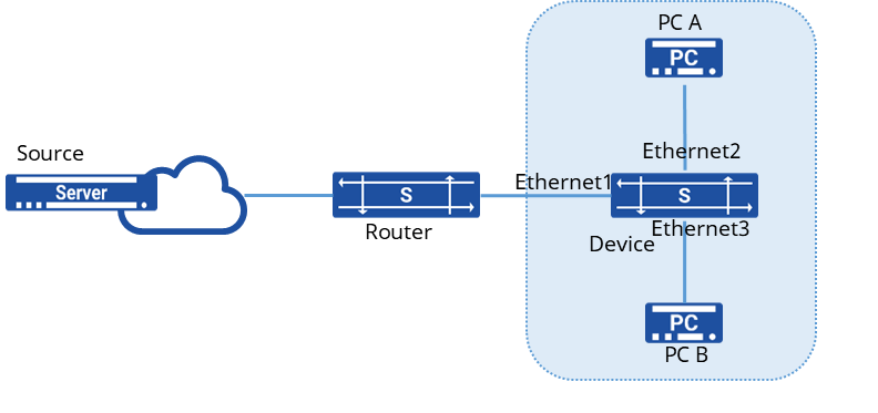
Router connects to user network as IGMP querier through Device, there are two users in the network, PC A and PC B. IGMP Snooping is running on Device, multicast source sends data to multicast group 224.1.1.1,225.1.1.1.
Procedure
1.Create VLANs and add member interfaces
sonic(config)# vlan 100sonic(config-vlan-100)# igmp snooping enablesonic(config)# port-group ethernet 1-3sonic(config-port-group-1-3)# switchport access vlan 100Verify configuration
1.View multicast group information
sonic# show l2-multicast-tableTotal L2_multicast_forwarding_group counters: 2(Source,Group) Interface Vlan-------------------- ----------- ------(0.0.0.0, 224.1.1.1) Ethernet2 100 Ethernet3 100(0.0.0.0, 225.1.1.1) Ethernet2 100 Ethernet3 1002.Send multicast messages with destination IP 224.1.1.1 and 225.1.1.1 respectively to confirm that A and B can receive the multicast messages.
MLD Snooping Configuration
Section titled “MLD Snooping Configuration”Introduction
Section titled “Introduction”MLD Snooping (Multicast Listener Discovery Snooping) is an IPv6 Layer 2 multicast protocol. In an IPv6 network, to avoid wasting bandwidth by broadcasting multicast packets within a local area network (LAN), MLD Snooping can be deployed in the Layer 2 network to achieve precise forwarding of multicast packets. Similar to an IPv4 multicast network, Layer 2 multicast devices can listen to and analyze MLD messages between multicast users and upstream routers. Based on this information, the devices establish Layer 2 multicast forwarding entries to control the forwarding of multicast data packets.
Explanation of Principles
Section titled “Explanation of Principles”The specific handling of different MLD actions by switches running MLD Snooping is as follows:
General Group Query Messages
When the switch receives MLD General Group Query messages, it forwards them out through all ports in the VLAN except the receiving port.
For the receiving port, the switch handles it as follows:
- If the dynamic router port is already included in the router port list, its aging timer is reset.
- If the dynamic router port is not yet included in the router port list, it is added to the router port list, and its aging timer is started.
MLD Report Messages A host will send an MLD Report message to the MLD querier in the following two situations:
- When a member host of a multicast group receives an MLD Query message, it responds with an MLD Membership Report message.
- If a host wants to join a multicast group, it proactively sends an MLD Membership Report message to the MLD querier to declare its membership in the multicast group.
When the switch receives an MLD Membership Report message, it forwards the message through all router ports within the VLAN, parses the multicast group address that the host wants to join from the message, and processes the receiving port as follows:
- If there is no forwarding entry corresponding to the multicast group, it creates a forwarding entry, adds the port as a dynamic member port to the outgoing port list, and starts its aging timer.
- If there is an existing forwarding entry for the multicast group, but the outgoing port list does not include the port, it adds the port as a dynamic member port to the outgoing port list and starts its aging timer.
- If there is an existing forwarding entry for the multicast group and the outgoing port list already includes the dynamic member port, it resets the aging timer.
Leaving Multicast Groups
When a host leaves a multicast group, it sends an MLD Leave Group message to inform the multicast router that it has left a specific multicast group.
- If the switch does not have a forwarding entry for the multicast group, or if the outgoing port list for the multicast group does not include the port, the switch will not forward the message to any port and will discard it.
- If there is a forwarding entry for the multicast group and the outgoing port list for the multicast group includes the port, the switch will forward the message through all router ports within the VLAN. Since the switch does not know whether there are other members of the multicast group on the receiving port, it will not immediately remove the port from the outgoing port list of the forwarding entry for the multicast group but will reset its aging timer.
MLD Snooping Configuration
Section titled “MLD Snooping Configuration”Configuring Basic MLD Snooping Functionality
Section titled “Configuring Basic MLD Snooping Functionality”| Operation | Command | Description |
|---|---|---|
| Enter the VLAN view | vlan ID | |
| Enable MLD Snooping function | mld-snooping enable | |
| Enable MLD Snooping querier | mld-snooping querier enable | |
| Configure the source address for MLD queries | mld-snooping querier-ip ip-address |
Configuring MLD Snooping Port Aging Time
Section titled “Configuring MLD Snooping Port Aging Time”After receiving different MLD protocol messages, the device starts aging timers for member ports with different durations:
- When member ports of the device receive Report messages from downstream hosts, the port aging time is set to: Robustness factor × General Query Interval + Maximum Response Time.
- When member ports of the device receive Leave messages from downstream hosts, the port aging time is set to: Specific Query Interval × Robustness factor.
| Operation | Command | Description |
|---|---|---|
| Enter the VLAN view | vlan ID | |
| Configure the MLD Snooping general query interval | mld-snooping query-interval value | |
| Configure the MLD Snooping maximum response time | mld-snooping query-max-response-time value | |
| Configure the MLD Snooping specific query interval | mld-snooping last-member-query-interval value | |
| Configure the MLD Snooping robustness factor | mld-snooping robustness value |
Enabling Fast Leave on Member Interfaces
Section titled “Enabling Fast Leave on Member Interfaces”Fast Leave on a port means that when the switch receives an MLD leave message from a host indicating it is leaving a multicast group, the switch immediately removes that port from the outgoing port list for the corresponding forwarding table entry. Subsequently, when the switch receives a specific MLD query message for that multicast group, it will no longer forward it out of that port.
| Operation | Command | Description |
|---|---|---|
| Enter the VLAN view | vlan ID | |
| Enable fast leave | mld-snooping fast-leave enable |
Enabling MLD Snooping Proxy Function
Section titled “Enabling MLD Snooping Proxy Function”When there are numerous member hosts in the network or when member hosts frequently join/leave multicast groups, a large number of MLD join/leave messages may be generated, resulting in significant processing pressure on the access devices. To reduce the number of MLD join and leave messages received by upstream devices, MLD Snooping Proxy functionality can be configured on edge devices to allow them to act as proxies for downstream hosts to send join and leave messages to upstream devices.
Handling of join messages:
- Upon receiving a join message for a multicast group on a port, if a forwarding table entry exists for that group and its outgoing port list already includes the dynamic member port, reset the aging timer for that entry.
- If a forwarding table entry exists for the multicast group but its outgoing port list does not include the port, add the port as a dynamic member port to the outgoing port list and start its aging timer.
- If no forwarding table entry exists for the multicast group on the device, create one, add the port as a dynamic member port to the outgoing port list, start its aging timer, and send a report message for that group to all router ports.
Handling of leave messages:
- Upon receiving a leave message for a multicast group on a port, send a specific query message for that group to the port.
- Only send a leave message for the group to all router ports when removing the last member port from the corresponding forwarding table entry for that multicast group.
Handling of general group query messages:
- Upon receiving a general group query message, forward it to all ports in the VLAN except the receiving port.
- Generate report messages based on locally maintained group membership relationships and forward them to all router ports simultaneously.
| Operation | Command | Description |
|---|---|---|
| Enter the VLAN view | vlan ID | |
| Enable MLD Snooping function | mld-snooping enable | |
| Enable MLD Snooping Proxy function | mld-snooping-proxy enable |
Multicast VLAN Configuration
Section titled “Multicast VLAN Configuration”Introduction
Section titled “Introduction”When users in different VLANs have the same multicast data requirements, the upstream router needs to send multiple copies of the same multicast packet, each carrying a different VLAN, to different VLANs. With multicast VLAN functionality deployed on Layer 2 devices, the upstream router no longer needs to replicate the multicast stream in each user VLAN. Instead, the data stream is duplicated within the multicast VLAN and then sent to the Layer 2 devices. This approach avoids unnecessary duplication of multicast streams on the upstream router, saving network bandwidth and reducing the burden on the upstream router.
Explanation of Principles
Section titled “Explanation of Principles”In a multicast VLAN, VLANs are divided into multicast VLANs and user VLANs. The multicast VLAN is the VLAN to which the interfaces connected to multicast sources belong, used to aggregate multicast streams. The user VLAN is the VLAN to which multicast member hosts belong, used to receive multicast traffic from the multicast VLAN. Multiple user VLANs can be bound to a multicast VLAN.
The implementation process of multicast VLAN functionality consists of two parts: protocol message forwarding and multicast data forwarding:
Protocol Message Forwarding
- Replace the Tag of IGMP Report messages from user VLANs with the Tag of the corresponding multicast VLAN and send them out from the router ports of the multicast VLAN.
- Replace the Tag of IGMP Query messages from the multicast VLAN with the Tag of the corresponding user VLAN and send them out from the member ports of the user VLAN.
- Merge the learned entries from IGMP Snooping in user VLANs into the multicast VLAN.
Multicast Data Forwarding
- If the forwarding table entry corresponding to the multicast VLAN is found, the outgoing ports and outgoing port VLAN IDs can be determined. Then, the data packet is copied and sent to each member port in each user VLAN.
- If the corresponding forwarding table entry is not found, the data packet will be discarded or broadcast according to user policy.
Multicast VLAN Configuration
Section titled “Multicast VLAN Configuration”| Operation | Command | Description |
|---|---|---|
| Enter the system configuration view | configure | |
| Configure the multicast vlan | igmp-snooping mvlan multicast-vlan user-vlan | multicast-vlan: Multicast VLAN; user-vlan: User VLAN, supports configuring multiple VLANs separated by commas ’,’ or configuring a range using ’-‘ |
Display and Maintenance
Section titled “Display and Maintenance”| Operation | Command | Description |
|---|---|---|
| View multicast VLAN configuration | show vlan igmp-snooping mvlan vlan-id vlan-id |
Configuration Example
Section titled “Configuration Example”Network requirements
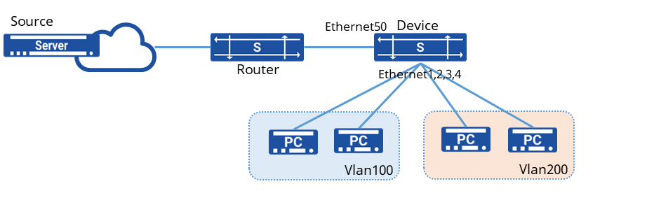
The service VLAN used to transmit multicast data between Router and Device is VLAN 10, while the downstream user hosts belong to VLAN 100 and VLAN 200 respectively, and all need to receive multicast data from Multicast Source. By configuring the multicast VLAN one-to-one multifunction based on user VLANs, for multiple copies of the same multicast demand from different user hosts, Router only needs to send one copy of multicast data to VLAN 10, reducing the bandwidth waste between Router and Device.
Procedure
1.Create a VLAN and enable IGMP Snooping
sonic(config)# vlan 100sonic(config-vlan-100)# igmp snooping enablesonic(config)# vlan 200sonic(config-vlan-200)# igmp snooping enable2.Create a multicast VLAN and enable IGMP Snooping
sonic(config)# vlan 10sonic(config-vlan-10)# igmp snooping enable3.Add the interface to the specified VLAN
sonic(config)# vlan 100sonic(config)# vlan 200sonic(config)# vlan 10sonic(config)# interface ethernet 1sonic(config-if-1) switchport access vlan 100sonic(config)# interface ethernet 2sonic(config-if-2) switchport access vlan 100sonic(config)# interface ethernet 3sonic(config-if-3) switchport access vlan 200sonic(config)# interface ethernet 4sonic(config-if-4) switchport access vlan 200sonic(config)# interface ethernet 50sonic(config-if-50) switchport access vlan 104.Bind user Vlan100, Vlan200 under multicast VLAN
sonic(config)# igmp-snooping mvlan 20 200,201Verify configuration
View multicast VLAN configuration
sonic# show vlan igmp-snooping mvlan+-------------+-------------+| MVLAN ID | UVLAN IDS |+=============+=============+| 20 | 200 || | 100 |+-------------+-------------+PIM-SM Configuration
Section titled “PIM-SM Configuration”Introduction
Section titled “Introduction”PIM, short for Protocol Independent Multicast, refers to the ability to utilize either static routes or any unicast routing protocol (including RIP, OSPF, IS-IS, BGP, etc.) to generate a unicast routing table that provides routing for IP multicast. Multicast routing is independent of the unicast routing protocol used, as long as the corresponding multicast routing entries can be created via the unicast routing protocol. As a multicast routing solution, it directly leverages the routing information from the unicast routing table to perform an RPF (Reverse Path Forwarding) check on multicast packets. After the check passes, multicast routing entries are created to forward the multicast packets. As an intra-domain multicast routing protocol, PIM supports two modes: Dense Mode (PIM-DM) and Sparse Mode (PIM-SM). The current version only supports Sparse Mode.
In the ASM (Any-Source Multicast) model, PIM-SM uses a “pull mode” to forward multicast packets. It is typically deployed in networks where multicast group members are relatively large in scale and sparsely distributed. Based on this sparse network model, its implementation works as follows:
- A crucial PIM router is maintained in the network: the Rendezvous Point (RP), which serves any group members or multicast sources that may appear at any time. All PIM routers in the network know the location of the RP.
- When a group member appears (a user host joins a multicast group G via IGMP), the last-hop router sends a Join message toward the RP, hop by hop, to create a (*, G) entry and build an RPT (Rendezvous Point Tree) rooted at the RP.
- When an active multicast source appears (a multicast source sends the first multicast data packet to a multicast group G), the first-hop router encapsulates the multicast data in a Register packet and unicasts it to the RP. The RP then creates an (S, G) entry to register the source information.
In the ASM model, key mechanisms of PIM-SM include neighbor discovery, DR election, RP discovery, RPT construction, multicast source registration, SPT switchover, and assert.
Basic Concepts
Section titled “Basic Concepts”RPF Check
Section titled “RPF Check”In unicast routing and forwarding, a unicast packet travels along a point-to-point path. A router only needs to consider “where the packet needs to go”—the destination address—to determine which interface to forward it out of.
Multicast routing and forwarding are different. Because the destination address of a multicast packet is a multicast address, which merely identifies a group of receivers, it’s impossible to locate the receivers based on the destination address. However, the “source location” of the multicast packet—its source address—is definite. Therefore, the forwarding of multicast packets primarily relies on their source address to ensure the correctness of the forwarding path.
Upon receiving a multicast packet, a router consults the unicast routing table using the packet’s source address to find the route back to the packet’s source. It then checks whether the outgoing interface in the routing table entry for reaching the source matches the incoming interface on which the multicast packet was received. If they match, the multicast packet is considered to have arrived on the correct interface, thereby ensuring the correctness and uniqueness of the entire forwarding path. This process is called an RPF check. This “correct interface” is commonly referred to as the RPF interface, which is the interface that passes the RPF check.
Neighbor Discovery
Section titled “Neighbor Discovery”Each interface enabled with the PIM protocol on a PIM router periodically sends out Hello messages. The Hello message is encapsulated in a multicast packet with a destination address of 224.0.0.13 (representing all PIM routers on the same network segment), a source address of the interface’s IP address, and a TTL value of 1.
The purposes of the Hello message are: to discover PIM neighbors, to negotiate various PIM protocol parameters, and to maintain neighbor relationships.
DR Election
Section titled “DR Election”On a network segment where multicast sources or group members reside, multiple PIM routers are typically connected. These PIM routers become neighbors by exchanging Hello messages, which carry DR priority and the interface address on that segment. Each PIM router compares its own parameters with the information carried in the received Hello messages to elect a DR, which will be responsible for sending and receiving multicast packets on behalf of the source or group members on that segment. The election rules are as follows:
- The router with the higher DR priority wins (provided all PIM routers on the segment support DR priority in Hello messages).
- If the DR priorities are equal, or if at least one PIM router on the segment does not support carrying DR priority in Hello messages, the router with the numerically larger IP address wins.
If the current DR fails, causing PIM neighbor relationships to time out, a new round of DR election will be triggered among the remaining PIM neighbors.
In the ASM model, the primary roles of the DR are as follows:
- On the shared segment connected to a multicast source, the DR is responsible for sending Register registration messages to the RP. The DR connected to the multicast source is called the source-side DR.
- On the shared segment connected to group members, the DR is responsible for sending Join messages to the RP. The DR connected to group members is called the member-side DR.
RP Discovery
Section titled “RP Discovery”The Rendezvous Point (RP) is a crucial PIM router within the network, responsible for handling source-side DR registration information and group member join requests. All PIM routers in the network must know the address of the RP, which functions similarly to a central hub for supply and demand information.
A single RP can serve multiple multicast groups simultaneously, but a specific multicast group can only correspond to one RP. Currently, the RP can be configured using the following methods:
- Static RP: Configure the same RP address on all PIM routers within the network to statically designate the RP’s location.
- Dynamic RP: Select several PIM routers within the PIM domain and configure them as C-RP (Candidate-RP) to dynamically elect the RP through a process. Simultaneously, a BSR (Bootstrap Router) must be elected by configuring C-BSR (Candidate-BSR). The BSR collects advertisement information from the C-RPs and disseminates it to all PIM routers within the PIM-SM domain.
The current version only supports Static RP.
RPT Construction
Section titled “RPT Construction”The PIM-SM RPT (Rendezvous Point Tree) is a multicast distribution tree rooted at the RP, with the PIM routers connected to group members as its leaves. When a group member appears in the network (i.e., a user host joins a multicast group G via IGMP), the member-side DR sends a Join message towards the RP. This process creates (*, G) entries hop-by-hop along the path to the RP, ultimately forming an RPT rooted at the RP. During the RPT construction process, when a PIM router sends a Join message, it performs an RPF check: it looks up the unicast route to reach the RP. The outgoing interface of this unicast route becomes the upstream interface, and the next hop becomes the RPF neighbor. The Join message is then forwarded hop-by-hop starting from the member-side DR until it reaches the RP.
Multicast Source Registration
Section titled “Multicast Source Registration”In a PIM-SM network, any newly active multicast source must first “register” with the RP before its multicast traffic can be delivered to group members. The specific process is as follows:
- The multicast source sends its multicast packets to the source-side DR.
- Upon receiving the multicast packets, the source-side DR encapsulates them within a Register message and sends it to the RP.
- The RP receives the Register message, decapsulates it, establishes an (S, G) entry, and forwards the multicast data down the RPT towards the group members.
SPT Switchover
Section titled “SPT Switchover”In a PIM-SM network, a multicast group corresponds to only one RP and initially relies on a single RPT. Without SPT switchover, all multicast packets destined for the group must first be encapsulated in register messages sent to the RP. The RP then decapsulates them and forwards the packets along the RPT. This makes the RP a mandatory transit point for all multicast traffic, which can place a significant burden on it as the packet rate increases. To address this issue, PIM-SM allows either the RP or the member-side DR to trigger an SPT switchover to alleviate the load on the RP.
RP-Triggered SPT Switchover:
- After receiving a register message from the source-side DR, the RP forwards the encapsulated multicast packet down the RPT towards the group members. Simultaneously, the RP sends a Join message hop-by-hop towards the source-side DR.
- During this process, (S, G) entries are created on the PIM routers along the path, establishing an SPT from the RP back to the source.
Once the SPT is successfully built, the source-side DR can forward multicast packets directly to the RP along this tree, freeing both the source-side DR and the RP from the frequent encapsulation and decapsulation process.
Member-side DR Triggered SPT Switchover:
The member-side DR periodically monitors the forwarding rate of multicast packets. Once it detects that the forwarding rate for an (S, G) stream exceeds a configured threshold, it triggers an SPT switchover:
- The member-side DR sends a Join message hop-by-hop towards the source-side DR, creating (S, G) entries and establishing an SPT directly from the source-side DR to itself.
- After the SPT is established, the member-side DR sends a Prune message hop-by-hop up the RPT towards the RP, removing the corresponding downstream interface from the (*, G) entry. Once pruning is complete, the RP stops forwarding the multicast traffic for that group down the RPT to this member-side DR.
- If the newly built SPT does not pass through the RP, the RP will then send a Prune message hop-by-hop towards the source-side DR, removing the corresponding downstream interface from the (S, G) entry on that path. After this pruning, the source-side DR stops forwarding multicast packets for that group along the “source-side DR -> RP” segment of the SPT.
By default, devices generally do not have a multicast packet forwarding rate threshold configured. Therefore, both the RP and the member-side DR typically trigger their respective SPT switchover processes upon receiving the first multicast packet for a given (S, G) stream.
Assert Mechanism
Section titled “Assert Mechanism”When multiple PIM routers connected to the same network segment pass the RPF check and attempt to forward multicast packets onto that segment, the Assert mechanism is needed to ensure that only one PIM router forwards the multicast packets onto the segment. After receiving identical multicast packets from a neighbor router, a PIM router sends an Assert message to all PIM routers on the segment via multicast, using the permanent group address 224.0.0.13 as the destination.
Upon receiving the Assert message, other PIM routers compare their own parameters with those carried in the received message to participate in an Assert election. The election rules are as follows:
- The router with the higher unicast routing protocol preference wins.
- If the preferences are equal, the router with the lower metric (cost) to the multicast source wins.
- If the above are all equal, the router with the numerically higher downstream interface IP address wins.
Based on the Assert election result, routers perform different actions:
- The downstream interface of the winner is called the Assert Winner and becomes responsible for subsequently forwarding multicast packets onto that network segment.
- The downstream interface of the loser is called the Assert Loser. It will not forward multicast packets onto that segment subsequently, and the PIM router also removes it from the downstream interface list in the (S, G) entry.
After the Assert election concludes, only one downstream interface remains active on the segment, transmitting only one copy of the multicast packet. All Assert Losers can periodically resume multicast packet forwarding, thereby triggering periodic Assert elections.
PIM Configuration
Section titled “PIM Configuration”PIM Interface
Section titled “PIM Interface”| Operation | Command | Description |
|---|---|---|
| Enter the system configuration view | configure | |
| Enter the interface view | interface ethernet interface_id | |
| Enable PIM functionality | ip pim |
Configure static RP
Section titled “Configure static RP”| Operation | Command | Description |
|---|---|---|
| Enter the system configuration view | configure | |
| Configure static RP | ip pim rp A.B.C.D A.B.C.D/M | A.B.C.D is the RP address; A.B.C.D/M is the multicast group address (with subnet mask) |
Configuring the Source-Side DR
Section titled “Configuring the Source-Side DR”| Operation | Command | Description |
|---|---|---|
| Enter the system configuration view | configure | |
| Enter the interface view | interface ethernet interface_id | Interface connected to the multicast source |
| Enable PIM functionality | ip pim | |
| Enable source-side DR registration | unknown-multicast trap | at the system configuration level, configure to send unknown multicast packets to the CPU |
Configuring the Member-side DR
Section titled “Configuring the Member-side DR”| Operation | Command | Description |
|---|---|---|
| Enter the system configuration view | configure | |
| Enter the VLANIF view | interface vlan vlan-id | VLAN connected to host terminals |
| Enable PIM functionality | ip pim | |
| Enable IGMP functionality | ip igmp |
Configure static multicast route
Section titled “Configure static multicast route”| Operation | Command | Description |
|---|---|---|
| Enter the system configuration view | configure | |
| Enter the interface view | interface ethernet interface_id | |
| Configure static multicast route | ip mroute ethernet interface_id A.B.C.D A.B.C.D |
Display and Maintenance
Section titled “Display and Maintenance”| Operation | Command | Description |
|---|---|---|
| Display PIM interface information | show ip pim interface | |
| Display PIM neighbor information | show ip pim neighbor | |
| Display RP information | show ip pim rp-info | |
| Display multicast routing information | show ip mroute | |
| Display RPF interface information | show ip pim rpf |
Configuration Example
Section titled “Configuration Example”Network requirements
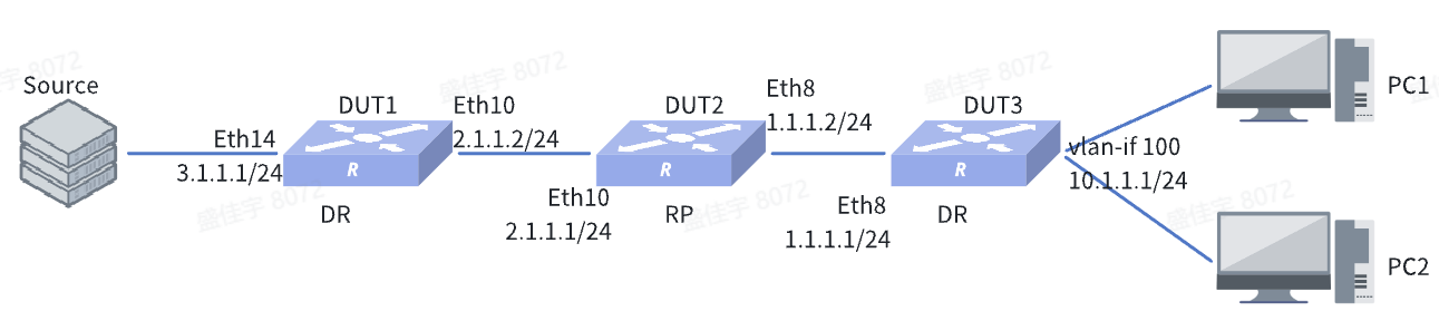
The host and the multicast source are interconnected at Layer 3 through three devices, with all devices running the OSPF protocol. The requirement is for host PC to be able to subscribe to services from the multicast source over the Layer 3 network.
Procedure
1.DUT3
Assign IP addresses to interfaces
sonic(config)# interface ethernet 8sonic(config-if-8)# ip address 1.1.1.1/24sonic(config-if-8)# interface ethernet 14sonic(config-if-14)# switchport access vlan 100sonic(config-if-14)# interface ethernet 15sonic(config-if-15)# switchport access vlan 100sonic(config-if-15)# exitsonic(config)# interface vlan 100sonic(config-vlanif-100)# ip address 10.1.1.1/24sonic(config-vlanif-100)# exitconfigure OSPF
sonic(config)# router ospfsonic(config-router)# ospf router-id 10.1.0.218sonic(config-router)# network 1.1.1.0/24 area 10sonic(config-router)# network 10.1.1.0/24 area 10sonic(config-router)# exitconfigure PIM-related settings
sonic(config)# interface ethernet 8sonic(config-if-8)# ip pimsonic(config-if-8)# exitsonic(config)# interface vlan 100sonic(config-vlanif-100)# ip pimsonic(config-vlanif-100)# ip igmpsonic(config-vlanif-100)# exitsonic(config)# ip pim rp 2.1.1.1 224.10.10.0/24sonic(config)# unknown-multicast trap2.DUT2
Assign IP addresses to interfaces
sonic(config)# interface ethernet 8sonic(config-if-8)# ip address 1.1.1.2/24sonic(config-if-8)# interface ethernet 10sonic(config-if-10)# ip address 2.1.1.1/24sonic(config-if-10)# exitconfigure OSPF
sonic(config)# router ospfsonic(config-router)# ospf router-id 10.1.0.217sonic(config-router)# network 1.1.1.0/24 area 10sonic(config-router)# network 2.1.1.0/24 area 10sonic(config-router)# exitconfigure PIM-related settings
sonic(config)# interface ethernet 8sonic(config-if-8)# ip pimsonic(config-if-8)# interface ethernet 10sonic(config-if-10)# ip pimsonic(config)# ip pim rp 2.1.1.1 224.10.10.0/24sonic(config)# unknown-multicast trap3.DUT1
Assign IP addresses to interfaces
sonic(config)# interface ethernet 10sonic(config-if-10)# ip address 2.1.1.2/24sonic(config-if-8)# interface ethernet 14sonic(config-if-14)# ip address 3.1.1.1/24sonic(config-if-14)# exitconfigure OSPF
sonic(config)# router ospfsonic(config-router)# ospf router-id 10.1.0.212sonic(config-router)# network 2.1.1.0/24 area 10sonic(config-router)# network 3.1.1.0/24 area 10sonic(config-router)# exitconfigure PIM-related settings
sonic(config)# interface ethernet 10sonic(config-if-10)# ip pimsonic(config-if-8)# interface ethernet 14sonic(config-if-14)# ip pimsonic(config)# ip pim rp 2.1.1.1 224.10.10.0/24sonic(config)# unknown-multicast trapVerify configuration
The device establishes PIM dynamic forwarding entries, enabling the on-demand multicast data to be correctly forwarded to the PC.