
PPPoE Interface Configuration Guide
Introduction
Section titled “Introduction”PPPoE(Point-to-Point Protocol over Ethernet) is an Ethernet-based WAN access protocol defined by RFC 2516.It combines the authentication, accounting, and link control functions of the PPP(Point-to-Point Protocol) with the flexible networking features of the Ethernet.It is mainly used to establish point-to-point logical connections in a shared Ethernet environment.
Explanation of Principles
Section titled “Explanation of Principles”PPPoE connection establishment is divided into two phases:
- Discovery phase.
The discovery phase is completed by the following packets:
1.PADI(PPPoE Active Discovery Initiation):The client broadcasts a PADI packet to find an available PPPoE server.
2.PADO(PPPoE Active Discovery Offer):The server responds to the PADO message, indicating that the service is available.
3.PADR(PPPoE Active Discovery Request):The client selects the server and sends a PADR request.
4.PADS(PPPoE Active Discovery Session-confirmation):The server assigns the Session ID to confirm the session establishment.
- Session phase.
1.Based on the PPP Protocol, LCP(Link Control Protocol) negotiation is completed, authentication packet(CHAP) authentication, and IPCP(IP Control Protocol) completes IP address assignment.
PPPoE session termination phase:
- Session termination phase.
1.PADT(PPPoE Active Discovery Terminate):This parameter is generated by a client or server to notify the peer to release PPPoE session resources
PPPoE Client Configuration
Section titled “PPPoE Client Configuration”Dial interface configuration
Section titled “Dial interface configuration”Create a logical interface for a PPPoE client to centrally manage PPP parameters and bind physical interfaces.
| Operation | Command | Description |
|---|---|---|
| Enter the system configuration view | configure | |
| Create a Dialer interface | interface dialer ID | ID is Dialer ID |
PPP authentication user name and password configuration
Section titled “PPP authentication user name and password configuration”Configure authentication management. The PPPoE server can use this information to verify the client validity. Ensure that the user name and password are the same as those configured on the PPPoE server.
| Operation | Command | Description |
|---|---|---|
| Enter the Dialer interface configuration view | interface dialer | |
| Configure the PPP authentication user name and password | ppp chap username username password |
MTU configuration
Section titled “MTU configuration”PPPoE encapsulation consumes 8 bytes (6 bytes PPPoE header + 2 bytes PPP protocol number). To avoid fragmentation and increase the risk of packet loss, flexible adjustment is required. In addition, ensure that the end-to-end MTU is consistent.
| Operation | Command | Description |
|---|---|---|
| Enter the Dialer interface configuration view | interface dialer | |
| Configure MTU | mtu mtu | the value of MTU,the default value is 1492 |
NAT configuration
Section titled “NAT configuration”To enable Intranet devices to access the Internet through PPPoE public IP addresses, the NAT(network address translation) is required.
| Operation | Command | Description |
|---|---|---|
| Enter the Dialer interface configuration view | interface dialer | |
| Configure nat-zone | nat-zone id |
Port binding configuration
Section titled “Port binding configuration”Associate a physical interface with a Dialer interface to enable PPPoE traffic to be transmitted over a specified physical link.
| Operation | Command | Description |
|---|---|---|
| Enter the interface view | interface ethernet ID | |
| Configure Binding a PPPoE client | pppoe-client id | The ID here is the ID of a dialer interface |
PPPoE Server Configuration
Section titled “PPPoE Server Configuration”PPPoE Server is used to provide layer 2 discovery (PADI/PADO) and layer 3 session capabilities for PPPoE clients in the access network. Through username/password authentication, it dynamically assigns network parameters such as IP addresses and DNS to clients, and supports large-scale concurrent session control.
On the SONiC device, PPPoE Server is usually deployed on the physical port or sub interface, which carries the terminal or access server downward, and accesses the Internet through the three-layer gateway or NAT outlet upward.
pppoe-server interface configuration
Section titled “pppoe-server interface configuration”Create a logical interface for a PPPoE client to centrally manage PPP parameters and bind physical interfaces.
| Operation | Command | Description |
|---|---|---|
| Enter the system configuration view | configure | |
| Create a Dialer interface | interface pppoe-server ID | The ID configuration range is from 0 to 7 |
ac-name configuration
Section titled “ac-name configuration”Create the Access Concentrator name for the PPPoE server, which will be carried in the PADO message as an optional field.
| Operation | Command | Description |
|---|---|---|
| Enter the pppoe server interface configuration view | interface pppoe-server ID | The ID configuration range is from 0 to 7 |
| Configure Access Concentrator Name | ac-name string | The range of String configuration is 1~63 |
DNS Server Configuration
Section titled “DNS Server Configuration”Configure the DNS IP sent by the PPPoE server to the client as an optional field.
| Operation | Command | Description |
|---|---|---|
| Enter the pppoe server interface configuration view | interface pppoe-server ID | The ID configuration range is from 0 to 7 |
| Configure the DNS server IP provided by the server to the client | dns-server A.B.C.D | The range of String configuration is 1~63 |
Service type configuration
Section titled “Service type configuration”Configure the service name of the PPPoE server and include this field in the PADO message; Simultaneously supports two switches, one for specifying the acceptance of any service type from the client, and a total of for specifying the allowed service types for the client to be empty. This field is optional.
| Operation | Command | Description |
|---|---|---|
| Enter the pppoe server interface configuration view | interface pppoe-server ID | The ID configuration range is from 0 to 7 |
| Configure the service type of the server | service-name string | Specify service name |
| Enable allowing all types of services on the client side | accept-any-service enable | Allow/Cancel Enable |
| Enable allowing client service type to be empty | accept-blank-service enable | Allow/Cancel Enable |
keepalive configuration
Section titled “keepalive configuration”Configure the keep alive interval on the PPPoE server side. If the retry count is exceeded, the dead connection will be disconnected. This field is optional.
| Operation | Command | Description |
|---|---|---|
| Enter the pppoe server interface configuration view | interface pppoe-server ID | The ID configuration range is from 0 to 7 |
| Configure the keep alive interval of the server | keepalive interval | Interval: The configuration range is 0~65535 |
Local ip configuration
Section titled “Local ip configuration”Configure the local IP address of the PPPoE server, which is the layer 3 address used to establish PPP connections, and be careful not to conflict with the remote ip pool.
| Operation | Command | Description |
|---|---|---|
| Enter the pppoe server interface configuration view | interface pppoe-server ID | The ID configuration range is from 0 to 7 |
| Configure the local IP address of the server | local-ip A.B.C.D v4/v6 mask | Configuration example: local-ip 192.168.3.1 255.255.255.0 |
MRU configuration
Section titled “MRU configuration”Configure the maximum receiving unit on the PPPoE server side, which defaults to 1492. The final receiving unit size will be negotiated with the mru value on the client side. The final mtu value can be viewed on the PPP interface through the ifconfig command to determine the negotiation result. Note that the MTU value on the server side is determined entirely based on the MRU negotiation results, otherwise the default value of 1492 will be used. This field is optional.
| Operation | Command | Description |
|---|---|---|
| Enter the pppoe server interface configuration view | interface pppoe-server ID | The ID configuration range is from 0 to 7 |
| Configure the MRU of the server | mru value | Value configuration range: 1312~10218 |
Remote ip pool configuration
Section titled “Remote ip pool configuration”Configure the PPPoE server to provide users with an address pool for dial-up authentication addresses, specifying pre configured IP ports that support both range and mask configuration methods.
| Operation | Command | Description |
|---|---|---|
| Enter the pppoe server interface configuration view | interface pppoe-server ID | The ID configuration range is from 0 to 7 |
| Configure the address pool provided by the server for the client | remote-ip-pool string | String: The configuration range is 1~32 |
| In the system configuration view, configure ip pool | ip-pool string | String: The configuration range is 1~32 |
| Enter the IP pool configuration view | ip-mask ip-address | IP address: supports configuring A.B.C.D/mask or A:: B/mask |
| Enter the IP pool configuration view | ip-range start-ip end-ip | Start ip, end ip: both support configuring A.B.C.D/A/B |
Session-max configuration
Section titled “Session-max configuration”Configure PPPoE server-side to support the maximum number of dial-up authentication sessions established for clients. This field is optional.
| Operation | Command | Description |
|---|---|---|
| Enter the pppoe server interface configuration view | interface pppoe-server ID | The ID configuration range is from 0 to 7 |
| Configure the maximum number of dial-up authentication sessions that the server can establish for clients | session-max value | Value: The configuration range is 1~65535 |
Example of PPPoE Client Configuration
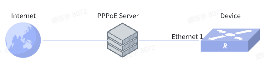
Section titled “Example of PPPoE Client Configuration”Network requirements
When a PPPoE server connects to the device, set an authentication user name and password on the server. The device has been configured with a PPPoE client and correctly obtained an IP address from the server address pool, and can access the Internet.
Procedure
1.Create Dialer interface 1
sonic(config)# interface dialer 12.Configure the same user name and password as the PPPoE server
sonic(config-dialerif-1)# ppp chap username test1 123abc3.Configure MTU
sonic(config-dialerif-1)# mtu 14924.Configure the port binds the Dialer interface
sonic(config-dialerif-1)# exitsonic(config)# interface ethernet 1sonic(config-if-1)# pppoe-client 1Verify configuration
The device interface has been successfully assigned to the IP address in the PPPoE server address pool, after the default route is configured, the device can access the Internet.
Example of PPPoE Server Configuration
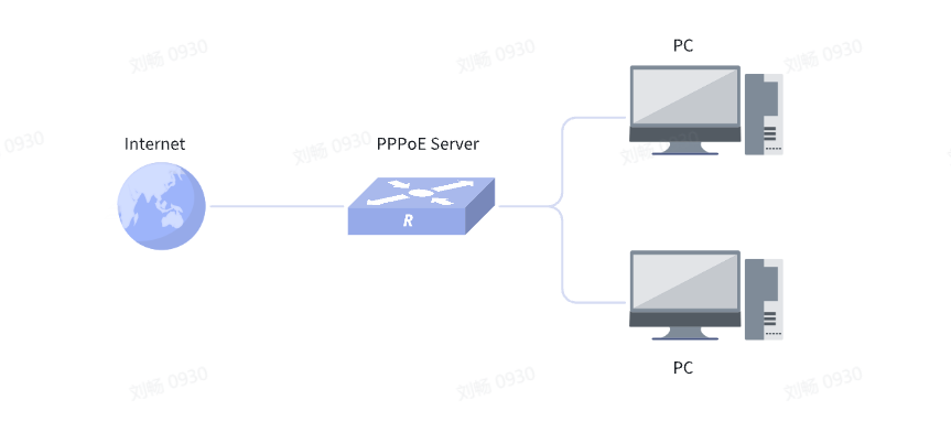
Section titled “Example of PPPoE Server Configuration”Network requirements
The PPPoE client accesses the SONiC device through the two-layer Ethernet. The device, as the PPPoE server, provides user authentication, session establishment and address allocation capabilities. The client successfully obtains the address pool IP and accesses the upstream network or Internet through the device.
Procedure
1.Configure ip pool and configure pppoe server interface
sonic(config)# ip-pool pppoe-pool1sonic(config-ippool-pppoe-pool1)# ip-range 192.168.15.10 192.168.15.20sonic(config)# interface pppoe-server 12.Configure ip pool and configure pppoe server interface
sonic(config-if-pppoeserver-1)# ppp chap username test1 test13.Configure the address pool for client IP allocation
sonic(config-if-pppoeserver-1)# remote-ip-pool pppoe-pool14.Configure the local IP address of the server
sonic(config-if-pppoeserver-1)# local-ip 192.168.15.1 255.255.255.05.Configure other server parameters
sonic(config-if-pppoeserver-1)# dns-server 8.8.8.8sonic(config-if-pppoeserver-1)# ac-name pppoe-server-1sonic(config-if-pppoeserver-1)# keepalive 15sonic(config-if-pppoeserver-1)# mru 1400sonic(config-if-pppoeserver-1)# service-name TESTsonic(config-if-pppoeserver-1)# session-max 3006.Port binding pppoe server interface
sonic(config)# interface ethernet 2sonic(config-if-2)# pppoe-server 1Verify configuration
The PC can successfully obtain the IP address in the remote ip pool through dial-up authentication of the pppoe server service provided by the device. As the server, the device can view the relevant statistics and session establishment status corresponding to each server interface.