
Reliability Configuration Guide
BFD Configuration
Section titled “BFD Configuration”Introduction
Section titled “Introduction”Bidirectional Forwarding Detection (BFD) is a unified network-wide detection mechanism used to quickly monitor the forwarding connectivity status of links or IP routes within a network. When certain links do not provide hardware detection, applications rely on the upper-layer protocol’s own Hello message mechanism for fault detection. However, the fault detection time of upper-layer protocols is usually above 1 second, which is unacceptable for some applications. The BFD protocol was developed in this context. BFD provides a standardized, media-independent, and protocol-independent fast fault detection mechanism, enabling rapid detection and monitoring of the forwarding connectivity status of links or IP routes in the network. This improves network performance. By quickly detecting communication failures between neighboring systems, users can establish backup channels more quickly to recover communication and ensure network reliability.
Explanation of Principles
Section titled “Explanation of Principles”BFD (Bidirectional Forwarding Detection) is used to establish sessions between two network devices to detect bidirectional forwarding paths and provide services to upper-layer applications. BFD itself does not have a discovery mechanism; instead, it relies on upper-layer protocols to notify it of new neighbor relationships. When an upper-layer protocol establishes a new neighbor relationship, it informs BFD of the neighbor’s parameters, and BFD establishes a session based on the received parameters. Once the session is established, both parties periodically send BFD packets to each other quickly. If no BFD packets are received from the peer within the detection time, the bidirectional forwarding path is considered to have failed. The failure information is then communicated to the upper-layer application served by the session, which takes appropriate action.
BFD Configuration
Section titled “BFD Configuration”| Configure Tasks | Instructions | Index |
|---|---|---|
| Create a BFD session | Required | Creating a BFD Session |
| Configure the detection multiplier for the BFD session | Optional | Configuring the Detection Multiplier for the BFD Session |
| Configure the minimum transmit interval for BFD packets | Optional | Configuring the Minimum Transmit Interval for BFD Packets |
| Configure the BFD mode as passive | Optional | Configuring the BFD Mode as Passive |
| Configure the receive interval for BFD packets | Optional | Configuring the Receive Interval for BFD Packets |
| Configure the transmit interval for BFD packets | Optional | Configuring the Transmit Interval for BFD Packets |
| Terminate BFD session detection | Optional | Terminate BFD Session Detection |
| Configure the BFD session as single-arm echo function | Optional | Configuring Single-arm Echo Function |
| Configure BFD policy group and bind it to the peer | Optional | Configuring BFD Policy Group |
Creating a BFD Session
Section titled “Creating a BFD Session”| Operation | Command | Description |
|---|---|---|
| Enter the system configuration view | configure terminal | |
| Enter the BFD view | bfd | |
| Create a BFD session and enter the BFD-peer view | peer<ip-address>[{multihop|local-address<ip-address>|interface <interface-type> <interface-name>}] | <peer-address>: IP address of the peer device <session-name>: The name of the BFD session <local-address>: The desired local IP address for sourcing BFD packets <interface-type>: The type of the interface <interface-number>: Interface number |
Configuring the Detection Multiplier for the BFD Session
Section titled “Configuring the Detection Multiplier for the BFD Session”The detection time of a BFD session is determined by the local detection multiplier configured for that session. Users can adjust the local detection multiplier based on the actual network conditions to increase or decrease the detection time of the BFD session. For example, for a relatively stable link where frequent detection of link status is not necessary, you can increase the local detection multiplier.
The formula to calculate the BFD detection time is:
BFD Detection Time = Local Detection Multiplier x Transmission Interval
| Operation | Command | Description |
|---|---|---|
| Enter the BFD-peer view | peer <ip-address> | |
| Configure the detection multiplier for the BFD session | detect-multiplier<value> | The range of value is: 2-255 |
Configuring the Minimum Transmit Interval for BFD Packets
Section titled “Configuring the Minimum Transmit Interval for BFD Packets”BFD (Bidirectional Forwarding Detection) protocol relies on the Time To Live (TTL) field in its packets to play a crucial role in network operations. Used for swiftly detecting the availability of network paths, BFD monitors link status by sending probing packets. The TTL field specifies the maximum time or hop count that a packet can exist in the network.
Here’s how the TTL field functions:
- Limiting packet propagation: The TTL field restricts the scope of BFD probing packets within the network. When a packet reaches its designated TTL, it is discarded, preventing it from indefinitely propagating across the network.
- Rapid fault detection: TTL assists BFD in swiftly detecting link failures. If a probing packet fails to reach its destination within the specified TTL, BFD promptly concludes a link failure and notifies network devices to take appropriate actions, such as switching to alternate paths.
- Conserving network resources: By setting an appropriate TTL value, unnecessary network traffic can be minimized. Setting a TTL too high might waste bandwidth and processing resources, while setting it too low could burden network devices with frequent BFD packet processing.
| Operation | Command | Description |
|---|---|---|
| Enter the BFD-peer view | peer<ip-address> | |
| Configure the minimum transmit interval for BFD packets | minimum-ttl<value> | The range of value is: 1-254 |
Configuring the BFD Mode as Passive
Section titled “Configuring the BFD Mode as Passive”In passive mode, BFD (Bidirectional Forwarding Detection) operates by waiting for probe packets from the peer device and responding to them, rather than periodically sending its own probe packets.
Here’s how passive mode works:
- Waiting for peer probe packets: In passive mode, the device continuously listens for BFD probe packets from the peer device. These probe packets are typically sent at regular intervals.
- Responding to peer probe packets: Upon receiving BFD probe packets from the peer device, the device promptly responds. The response can be a simple acknowledgment or may include additional information such as packet sequence numbers.
- Detecting link status: The device determines the link status by responding to the peer’s probe packets. If no probe packets are received from the peer for a period of time, the device assumes that a link failure may have occurred and triggers the appropriate fault handling mechanism.
The advantage of passive mode is that it conserves bandwidth and processing resources since the device does not need to periodically send probe packets. It is suitable for scenarios where the link is stable, bandwidth is limited, or sensitivity to network resource consumption is high. However, passive mode may not promptly detect link failures because it relies on probe packets from the peer device.
| Operation | Command | Description |
|---|---|---|
| Enter the BFD-peer view | peer<ip-address> | |
| Configure the BFD mode as passive | passive-mode | The default value is active mode |
Configuring the Receive Interval for BFD Packets
Section titled “Configuring the Receive Interval for BFD Packets”| Operation | Command | Description |
|---|---|---|
| Enter the BFD-peer view | peer<ip-address> | |
| Configure the receive interval for BFD packets | receive-interval <value> | The range value is 10-60000 Unit is: ms |
Configuring the Transmit Interval for BFD Packets
Section titled “Configuring the Transmit Interval for BFD Packets”| Operation | Command | Description |
|---|---|---|
| Enter the BFD-peer view | peer<ip-address> | |
| Configure the transmit interval for BFD packets | transmit-interval <value> | The range value is 10-60000 Unit is: ms |
Terminate BFD Session Detection
Section titled “Terminate BFD Session Detection”| Operation | Command | Description |
|---|---|---|
| Enter the BFD-peer view | peer<ip-address> | |
| Terminate BFD session detection | shutdown |
Configuring Single-arm Echo Function
Section titled “Configuring Single-arm Echo Function”By configuring a unidirectional echo mode BFD session on the BFD-capable device, it can send BFD control packets to the non-BFD-capable device. When the non-BFD-capable device receives these packets, it simply loops them back at the IP layer. This loopback allows the BFD-capable device to detect link failures more quickly, as it can receive and process the echoed packets without waiting for a response from the non-BFD-capable device. This approach helps improve the efficiency of link failure detection in scenarios where only one device supports BFD.
| Operation | Command | Description |
|---|---|---|
| Enter the BFD-peer view | peer<ip-address> | |
| Configure the BFD session as single-arm echo function | echo-mode | |
| Configure the receive interval for BFD packets | echo-intervall <value> | The range value is 10-60000 Unit is: ms |
Configuring BFD Policy Group
Section titled “Configuring BFD Policy Group”Configuring BFD sessions individually can be time-consuming and inefficient, especially when dealing with a large number of sessions. By creating BFD policy groups, you can define common parameters for multiple BFD sessions and then simply bind the policy group to each peer, reducing the configuration workload and ensuring consistency across multiple sessions. This approach streamlines the configuration process and makes it more manageable, particularly in environments with numerous BFD sessions.
| Operation | Command | Description |
|---|---|---|
| Enter the BFD view | bfd | |
| Create a BFD policy group | profile<profile-name> | |
| Enter the BFD peer view | peer<ip-address> | |
| Bind BFD policy to peer | profile<profile-name> |
Display and Maintenance
Section titled “Display and Maintenance”| Operation | Command |
|---|---|
| Display the BFD session info | show bfd peers brief |
| Display the BFD session statistics info | show bfd peers counters |
BFD and BGP Linkage Configuration Example
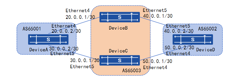
Section titled “BFD and BGP Linkage Configuration Example”Network requirements
In the network, Device A and Device D establish EBGP neighbors on Device B and Device C respectively, Device A can receive the route announced by BGP on Device D in the form of ECMP, and the next hops are Device B and Device C respectively. cut off Device A’s Ethernet 49 port The BFD can detect the link break quickly and converge the route quickly.
Procedure
1.Device A Configuration
# Interface configuration IP address
sonic(config)# interface ethernet 4sonic(config-if-4)# ip address 20.0.0.2/30sonic(config-if-4)# exitsonic(config)# interface ethernet 5sonic(config-if-5)# ip address 30.0.0.2/30sonic(config-if-5)# exitsonic(config)# interface loopback 0sonic(config-if-lo0)# ip address 10.1.15.10/32# Configuring EBGP connections
sonic(config)# router bgp 65003sonic(config-router)# bgp router-id 10.1.15.10sonic(config-router)# no bgp ebgp-requires-policysonic(config-router)# neighbor 20.0.0.1 remote-as 65003sonic(config-router)# neighbor 20.0.0.1 bfdsonic(config-router)# neighbor 20.0.0.1 description DeviceBsonic(config-router)# neighbor 30.0.0.1 remote-as 65003sonic(config-router)# neighbor 30.0.0.1 bfdsonic(config-router)# neighbor 30.0.0.1 description DeviceC2.Device B Configuration
# Interface configuration IP address
sonic(config)# interface ethernet 5sonic(config-if-5)# ip address 40.0.0.1/30sonic(config-if-5)# exitsonic(config)# interface loopback 0sonic(config-if-lo0)# ip address 10.1.15.20/32# Configuring EBGP connections
sonic(config)# router bgp 65003sonic(config-router)# bgp router-id 10.1.15.20sonic(config-router)# no bgp ebgp-requires-policysonic(config-router)# neighbor 20.0.0.2 remote-as 65001sonic(config-router)# neighbor 20.0.0.2 bfdsonic(config-router)# neighbor 20.0.0.2 description DeviceAsonic(config-router)# neighbor 40.0.0.2 remote-as 65002sonic(config-router)# neighbor 40.0.0.2 bfdsonic(config-router)# neighbor 40.0.0.2 description DeviceD3.Device C, device D configuration is similar
Verify configuration
1.View BGP, BFD session establishment.
2.Device on line speed forwarding can hit the traffic declared route on Device D, cut the link, verify the convergence time verify that the convergence time meets the millisecond requirements.
Monitor-Link Configuration
Section titled “Monitor-Link Configuration”Introduction
Section titled “Introduction”Monitor Link is an interface linkage solution that triggers changes in the up/down state of downstream interfaces based on the changes in the up/down state of a monitored device’s upstream interface. This triggering subsequently leads to topology protocol devices on downstream devices.
Explanation of Principles
Section titled “Explanation of Principles”Each Monitor Link group consists of two types of member interfaces: upstream interfaces and downstream interfaces. While a Monitor Link group can have multiple upstream or downstream interfaces, an interface can only belong to a single Monitor Link group.
- The upstream interface is the monitored interface, and its associated link is known as the upstream link. The state of the Monitor Link group is coordinated with the state of this interface. When all the uplink interfaces in the Monitor Link group are down, the Monitor Link group is considered down. Conversely, when all the uplink interfaces in the Monitor Link group are up, the Monitor Link group is considered up.
- The downstream interface is the monitoring interface, and its associated link is known as the downstream link. The state of this interface is synchronized with the state of the Monitor Link group. Changes in the up/down state of the Monitor Link group correspondingly affect the state of the downstream interface, ensuring consistency between the two.
Configuration Example
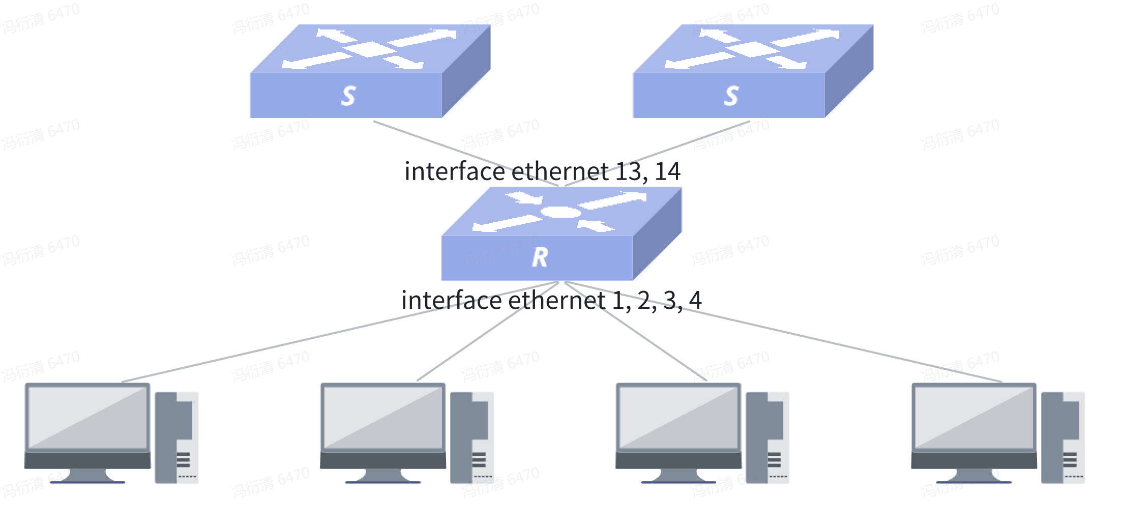
Section titled “Configuration Example”Network requirements
Device uses Ethernet ports 13,14 to connect to the uplink device and Ethernet ports 1,2,3,4 to connect to the downlink device. Requirements:
- When the upstream port all failure, need to promptly cut off the downstream port.
- When the uplink port restores connection, the downlink port connection is restored with a delay of 5 seconds to prevent frequent UP and DOWN of the downlink port caused by unstable link.
Procedure
# Create linkage group 1 and specify a delay time of 5 seconds
sonic(config)# monitor-link-group 1 5sonic(config-monitor-link-group-1)## Add uplink and downlink ports, support range configuration
sonic(config)# interface ethernet 13sonic(config-if-13)# monitor-link 1 uplinksonic(config)# interface ethernet 14sonic(config-if-14)# monitor-link 1 uplinksonic(config)# interface ethernet 1sonic(config-if-1)# monitor-link 1 downlinksonic(config)# interface ethernet 2sonic(config-if-2)# monitor-link 1 downlinksonic(config)# interface ethernet 3sonic(config-if-3)# monitor-link 1 downlinksonic(config)# interface ethernet 4sonic(config-if-4)# monitor-link 1 downlinkVerify configuration
sonic# show monitor-link+--------------+----------+------------------+---------------------+| Group Name | Delay | Uplink Members | Downlink Members |+==============+==========+==================+=====================+| 1 | 5 | Ethernet13 | Ethernet1 || | | Ethernet14 | Ethernet2 || | | | Ethernet3 || | | | Ethernet4 |+--------------+----------+------------------+---------------------+