
MAP Configuration Guide
Introduction
Section titled “Introduction”In the wave of transition from IPv4 to IPv6 networks, two primary conflicts persist:
- IPv4 Address Exhaustion vs Thriving IPv4 Services: The shortage of IPv4 addresses clashes with the continued vigorous development of IPv4-based services.
- Abundant IPv6 Address Space vs Scarce IPv6 Applications: The vast address space of IPv6 stands in contrast to the relative lack of widespread IPv6 applications.
On the IPv4 front, address reuse techniques (such as A+P) have seemingly alleviated the pressure of rapid IPv4 depletion. However, this requires significant investment in equipment and can adversely affect various applications to varying degrees. Regarding IPv6 development, the sensitivity to IPv4 address exhaustion differs among end-users, ICPs (Internet Content Providers), ISPs, and carriers, leading to an unbalanced development of the IPv6 ecosystem. While all parties are actively promoting IPv6 adoption, they harbor certain reservations. Furthermore, these two conflicts are interconnected: IPv4 address sharing mechanisms appear to slow down the development of the IPv6 industry chain, while the continuous evolution of the IPv6 ecosystem challenges the deployment scale of IPv4 sharing mechanisms.
To ensure the operation of existing IPv4 services while fostering the development of evolving IPv6 services, the 4over6 scenario has become a focal point for long-term evolution strategy research, given its ability to accommodate both IPv4 and IPv6 services. Within the 4over6 framework, various transition technologies have emerged. Among them, the Mapping of Address and Port (MAP) technology, which integrates stateless operation with dual translation/encapsulation techniques, has garnered significant attention as a leading IETF-recommended solution.
Definitions
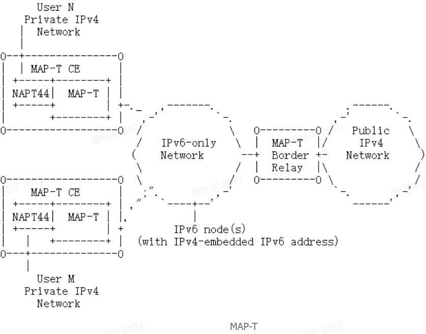
Section titled “Definitions”- MAP-T is the abbreviation for Mapping of Address and Port using Translation. It is defined as a stateless mapping and dual translation technology, and serves as an IPv6 transition technology within the 4over6 framework.
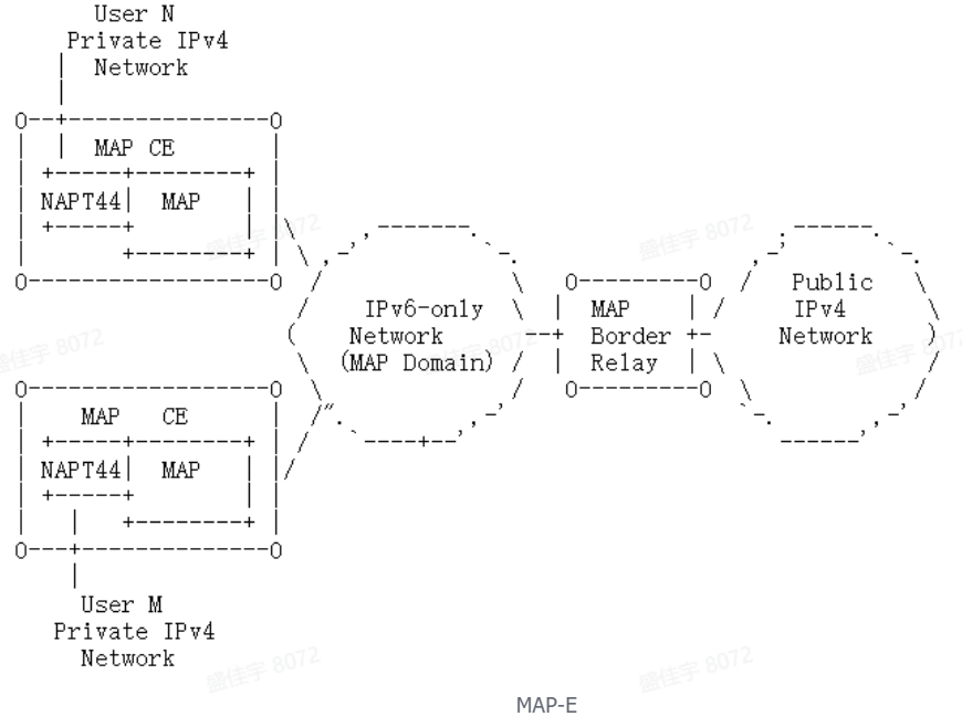
- MAP-E is the abbreviation for Mapping of Address and Port using Encapsulation. It is defined as a stateless mapping and dual encapsulation technology, and serves as an IPv6 transition technology within the 4over6 framework.
Architecture Overview
Section titled “Architecture Overview”The MAP technology combines stateless operation with dual translation/encapsulation techniques. MAP (Mapping of Address and Port) employs a stateless method for address and port multiplexing. Based on packet format, it is categorized into two types: dual-encapsulation MAP-E and dual-translation MAP-T. Fundamentally, MAP defines a stateless mechanism for address encapsulation or translation, enabling the transport of both IPv4 and IPv6 services over an IPv6-only network. The MAP domain, demarcated by border devices (MAP-CE and MAP-BR), is designed such that native IPv4 traffic resides exclusively outside its boundaries.
MAP-E / MAP-T Packet Processing Flow
Section titled “MAP-E / MAP-T Packet Processing Flow”Within the MAP domain, the network deploys an IPv6-only protocol stack. Traffic originating from IPv6 endpoints is natively carried over IPv6.
For traffic from IPv4 endpoints, an IPv6 tunnel must be established between a MAP-CE and a MAP-BR, or between two MAP-CEs. Depending on the method used to handle the IPv4 packets, the technology is categorized as either MAP-E or MAP-T
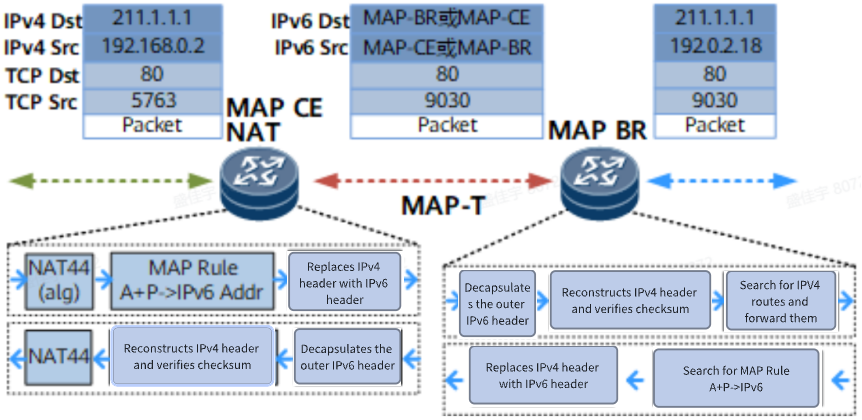
- MAP-T (Translation): Employs a translation method. The IPv4 header is translated into an IPv6 header, resulting in a packet with only a single IPv6 header.
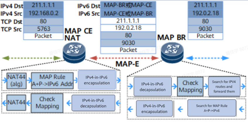
- MAP-E (Encapsulation): Employs an encapsulation method. The original IPv4 packet is encapsulated with an additional IPv6 header, resulting in an outer IPv6 header and an inner IPv4 header.

- MAP-T Data Processing Flow
- MAP-E Data Processing Flow
MAP-E / MAP-T Packet Processing Flow
Section titled “MAP-E / MAP-T Packet Processing Flow”Address Mapping
Section titled “Address Mapping”Address mapping between IPv4 and IPv6 is achieved by embedding specific portions of the IPv4 address and the port set identifier into an IPv6 address. The selected characteristic part from the IPv4 address is the IPv4-Addr-suffix, and from the Port-Set is the Port-Set Identifier (PSID). This process establishes a direct binding between the IPv4 address/port information and the IPv6 address, forming a stateless mapping.
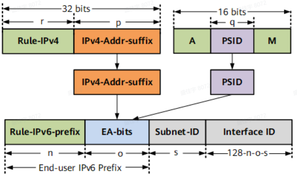
As illustrated in the preceding diagram depicting the mapping relationship between IPv4+Port and IPv6 addresses, the public IPv4 address and port set can be derived seamlessly by any node (whether a MAP-CE or MAP-BR) possessing the following key parameters:
- End-user IPv6 prefix (essential for obtaining the PSID)
- Rule IPv6 prefix
- EA-bits length
- Rule IPv4 prefix
- PSID offset
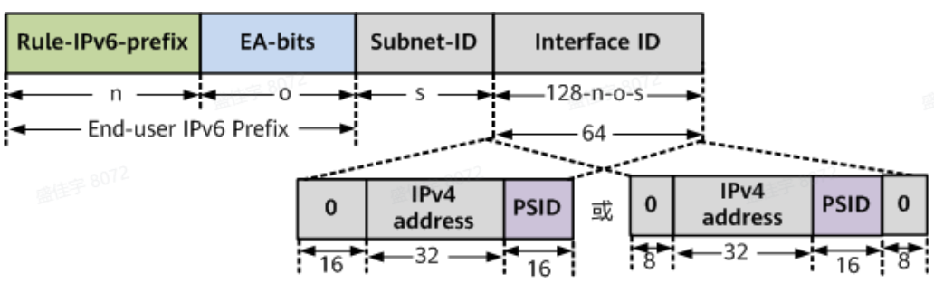
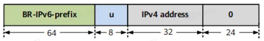
- Note: The length of the Subnet-ID is typically defined as 0. Furthermore, for a MAP-CE device, if the End-user-ipv6-prefix is longer than /64, it will override the Interface ID. The MAP technology constructs a unique identifier for a MAP-CE within the MAP domain by combining the IPv4 address and the Port-Set ID to form the Interface ID. This Interface ID is then appended to the End-user IPv6 prefix to synthesize a complete IPv6 address, which serves as the unique identifier for the MAP-CE. The Interface ID can be formed using one of two methods:
- RFC-compliant Method: The higher-order 16 bits are set to zero, combined with the IPv4 address field and the Port-Set ID field.
- Draft-compliant Method: The higher-order 8 bits and the lower-order 8 bits are set to zero, combined with the IPv4 address field and the Port-Set ID field. IPv4 Address Field Rules:
- If a public IPv4 address is assigned, the IPv4 address field is filled with this assigned address (32 bits in length).
- If an IPv4 prefix is assigned (e.g., to an enterprise user), the IPv4 address field must be right-padded with zeros to 32 bits. Example: If the assigned prefix is 1.1.1.0/29, the IPv4 address field must be set to 0x01010100 (in hexadecimal). Port-Set ID Field Rules:
- If the Port-Set ID value extracted from the EA-bits is less than 16 bits, it is right-padded with zeros to form a 16-bit field. Example: A Port-Set ID of 0xAC becomes 0xAC00.
- If an IPv4 prefix or a dedicated public IPv4 address is assigned (meaning no port sharing), there is no extractable Port-Set ID value. In this case, the Port-Set ID field is set to 0x0000. Through this process, a stateless, strong binding is established between the IPv4 address/port set of a user and their corresponding IPv6 address within the MAP domain. This binding enables the synthesized IPv6 address to uniquely identify the user across the entire MAP infrastructure.
Port Mapping
Section titled “Port Mapping”The “A+P” Concept
From the perspective of IPv4 addresses and transport-layer ports, the 32-bit IPv4 address space is limited. In contrast, the 16-bit transport-layer port space is currently underutilized. Therefore, the “A+P” (Address plus Port) model was introduced, which effectively extends the IPv4 address space by sharing public IPv4 addresses and partitioning the transport port space.
The MAP framework adopts this “A+P” concept, mapping a combination of a public IPv4 address and a port set to a private IPv4 address. Within MAP, the 16-bit transport-layer port number is divided into three distinct fields: A, Port-Set ID (PSID), and M.
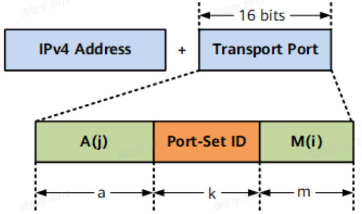
- Regarding A and a The port range 0-1023 is reserved for well-known ports. In MAP, this reserved range is recommended to be extended to 0-4095 (comprising 2¹² ports). This corresponds to a default recommended value of a = 4 (calculated as 16 total bits - 12 reserved bits = 4). The a parameter generally takes a non-zero value. If a = 0, it indicates that the entire port range is available for allocation.
- Regarding Port-Set ID (PSID) and k The length k of the Port-Set ID (PSID) determines the sharing ratio. The ratio value R = 2^k. This means the transport-layer port space is divided into 2^k distinct subsets, each allocated to a different CPE (Customer Premises Equipment) sharing the same public IPv4 address. Each CPE sharing the IPv4 address is assigned a unique PSID, which corresponds to a unique Port-Set.
- Regarding M and m The length m of the M field determines the contiguous length of ports within a single Port-Set. The contiguous length is 2^m. Through this division scheme:
- A total of 2^k Port-Sets are made available.
- Each Port-Set is identified by a unique PSID value.
- The number of ports contained within each PSID’s Port-Set is ((2^a) - 1) * (2^m). Example: MAP Mapping Rule Given a sharing ratio of R=1024 and a=4, we can derive m=2. Since each Port-Set is non-contiguous, the following table segments them for clarity. Taking PSID=0 as an example: When the prefix A is 0001 (listed as Contiguous Segment 1 in the table), the corresponding ports are:
- 0001000000000000 (4096)
- 0001000000000001 (4097)
- 0001000000000010 (4098)
- 0001000000000011 (4099) When the prefix A is 0010 (listed as Contiguous Segment 2), the corresponding ports are:
- 0010000000000000 (8192)
- 0010000000000001 (8193)
- 0010000000000010 (8194)
- 0010000000000011 (8195) This pattern continues for all possible values of A, establishing the complete correspondence between the PSID and its assigned Port-Set.
| PSID | Port-set-1(A=0001) | Port-set-2(A=0010) | … | Port-set-15(A=1111) |
|---|---|---|---|---|
| 0 | 4096,4097,4098,4099 | 8192,8193,8194,8195 | … | 61440,61441,61442,61443 |
| 1 | 4100,4101,4102,4103 | 8196,8197,8198,8199 | … | 61444,61445,61446,61447 |
| 2 | 4104,4105,4106,4107 | 8200,8201,8202,8203 | … | 61448,61449,61450,61451 |
| 3 | 4108,4109,4110,4111 | 8204,8205,8206,8207 | … | 61452,61453,61454,61455 |
| … | … | … | … | … |
| 1023 | 8188,8189,8190,8191 | 12284,12285,12286,12287 | … | 65532,65533,65534,65535 |
Mapping Rule Definitions
Section titled “Mapping Rule Definitions”The MAP technology utilizes three primary mapping rules:
- BMR (Basic Mapping Rule)
- FMR (Forwarding Mapping Rule)
- DMR (Default Mapping Rule) Note: Within the MAP-E context, the DMR is also referred to as the rule for handling “Destinations outside the MAP domain”. In the current implementation of the device’s MAP feature, the FMR is functionally consistent with the BMR and does not require separate configuration.
Basic Mapping Rule (BMR)(Mandatory)
Section titled “Basic Mapping Rule (BMR)(Mandatory)”The Basic Mapping Rule (BMR) is used to calculate the MAP Customer Edge (CE) device’s IPv4 address, Port-Set, and IPv6 address. Its primary function is to define the mapping relationship between an IPv6 address and the corresponding “IPv4 address + port” combination.
On the MAP-CE: The BMR is used to perform NAT44 translation on user IPv4 packets. Subsequently, it governs the encapsulation (for MAP-E) or translation (for MAP-T) of these translated packets into IPv6 format for transmission across the MAP domain.
On the MAP-BR: The BMR is applied to decapsulate (MAP-E) or translate (MAP-T) incoming IPv6 packets back into IPv4. For return traffic, the BR uses the same rule to re-encapsulate or re-translate the IPv4 packets into IPv6 and forwards them within the MAP domain towards the appropriate MAP-CE based on IPv6 routing.
The packets are then forwarded within the MAP domain to the destination MAP-CE via IPv6 routing. The fundamental parameters required for configuring the BMR include:
- Rule-IPv6-prefix
- Rule-IPv4-prefix
- EA-bits-length
- PSID-offset By configuring these parameters on a MAP-CE, the shared IPv4 address, the corresponding port set, and the MAP-CE’s own IPv6 address can be algorithmically derived. The MAP Domain can be logically partitioned into multiple sub-domains based on IPv4 subnets, where each IPv4 subnet segment constitutes a sub-domain. This architecture allows the Mapping Rule (MR) configuration for all MAP-CEs within a sub-domain to be simplified to a single, shared BMR. Each MAP-CE within the same sub-domain is configured with a unique End-user-IPv6-prefix but the same BMR.
Forwarding Mapping Rule (FMR)(Optional)
Section titled “Forwarding Mapping Rule (FMR)(Optional)”In the current device implementation, the FMR is functionally aligned with the BMR and does not require separate configuration. A detailed description is not provided at this time.
Default Mapping Rule (DMR)(Optional)
Section titled “Default Mapping Rule (DMR)(Optional)”- MAP-T: The Default Mapping Rule (DMR) handles packets whose destination IPv4 address lies outside the MAP Domain. These packets are forwarded by the MAP-BR to external networks. The DMR contains two parameters. Rule-IPv6-prefix: This is the IPv6 prefix of the MAP-BR. Rule-IPv4-prefix: This value is set to 0.0.0.0/0, making this rule function as the default route for IPv4 route matching on the MAP-CE. As illustrated in the figure below, when this rule is applied, the destination IPv6 address is formed by combining the DMR’s Rule-IPv6-prefix with the original destination IPv4 address.
- MAP-E: The rule is explicitly named “Destinations outside the MAP domain”, which more directly conveys its purpose. In MAP-E, where an IPv6 header encapsulates the original IPv4 packet, handling traffic destined outside the MAP domain simply requires adding an outer IPv6 header with the BR’s address. When this packet arrives at the MAP-BR, the device only needs to remove (decapsulate) the outer IPv6 header to reveal the original destination IPv4 address. Therefore, for MAP-E, configuring the “Destinations outside the MAP domain” rule essentially means configuring the IPv6 address of the MAP-BR.
MAP Configuration
Section titled “MAP Configuration”Enable MAP globally
Section titled “Enable MAP globally”| Operation | Command | Description |
|---|---|---|
| Enter the system configuration view | configure terminal | - |
| Enable MAP | map enable |
Configure MAP Rules
Section titled “Configure MAP Rules”| Operation | Command | Description |
|---|---|---|
| Enter the system configuration view | configure terminal | - |
| Configure BMR Rules | map-rule basic-mapping-rule rule_name rule-ip6-prefix ipv6_prefix rule-ip4-prefix ipv4_prefix ea-length Embedded_Address_bits psid-len psid_len psid-offset psid_offset | |
| Configure br-ipv6-address Rules | map-rule br-ipv6-address rule_name ipv6-address br_ipv6_address | Apply in MAP-E mode |
| Configure DMR Rules | map-rule default-mapping-rule rule_name ipv6-prefix ipv6_prefix | Apply in MAP-T mode |
| Configure local-ipv4-prefix Rules | map-rule local-ipv4-prefix rule_name | Within the MAP-CE domain, create a rule and then enter its local-ipv4-prefix rule view to configure the specific IP address prefix |
| Configure end-user-ipv6-prefix Rules | end-user-ipv6-prefix static X:X::X:X/M | Configuration within the MAP-CE Domain |
Create a MAP Domain
Section titled “Create a MAP Domain”| Operation | Command | Description |
|---|---|---|
| Enter the system configuration view | configure terminal | - |
| Create a MAP-E Domain | map-e domain domain_name {CE|BR} | |
| Create a MAP-T Domain | map-t domain domain_name {CE|BR} |
Bind a MAP Rule
Section titled “Bind a MAP Rule”| Operation | Command | Description |
|---|---|---|
| Enter the MAP domain configuration view | map-e domain domain_name {CE|BR} map-t domain domain_name {CE|BR} | - |
| Bind the BMR Rule | basic-mapping-rule rule_name | |
| Bind the br-ipv6-address Rule | br-ipv6-address rule_name | Apply in MAP-E mode |
| Bind the DMR Rule | default-mapping-rule rule_name | Apply in MAP-T mode |
| Bind the local-ipv4-prefix-rule | local-ipv4-prefix-rule rule_name | In the MAP-CE Domain |
Display and Maintenance
Section titled “Display and Maintenance”| Operation | Command | Description |
|---|---|---|
| Display port binding information | show map interface [role {CE|BR}] | - |
| Display MAP-E configuration | show map-e domain [name domain_name |role {CE|BR}] | |
| Display MAP-T configuration | show map-t domain [name domain_name |role {CE|BR}] | |
| Display MAP-E mode packet hit statistics | show map-e statistics [name domain_name |role {CE|BR}] | |
| Display MAP-T mode packet hit statistics | show map-t statistics [name domain_name |role {CE|BR}] |
Configuration Example
Section titled “Configuration Example”Network requirements
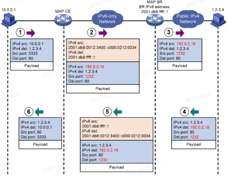
Network Setup and IPv4-IPv6 Address Translation Validation (Using MAP-E-BR as an Example)
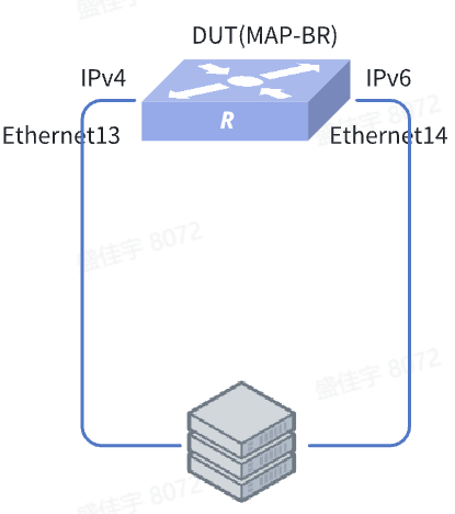
- Configure basic IP addresses on the device ports (Ethernet13 towards the IPv4 side, Ethernet14 towards the IPv6 side). Ensure the server ports are directly connected to the corresponding device ports.
sonic(config)# interface ethernet 13sonic(config-if-13)# ip address 192.0.2.1/24sonic(config-if-13)# interface ethernet 14sonic(config-if-14)# ip address 2001:db8:1012:1234::1/64- Enable the MAP-E-BR functionality on the port
sonic(config)# interface ethernet 13sonic(config-if-13)# nat64 map-zone-br enablesonic(config-if-13)# interface ethernet 14sonic(config-if-14)# nat64 map-zone-br enable- Configure a MAP rule and bind it to the MAP domain
sonic(config)# map-rule basic-mapping-rule BMR rule-ip6-prefix 2001:db8:1012::/48 rule-ip4-prefix 192.0.2.0/24 ea-length 16 psid-len 8 psid-offset 4sonic(config)# map-rule br-ipv6-address BRaddr ipv6-address 2001:db8:1012:1234::10/64sonic(config)# map-e domain test1 BRsonic(config-map-e-domain-test1)# basic-mapping-rule BMRsonic(config-map-e-domain-test1)# br-ipv6-address BRaddrVerify configuration
Send IPv4/IPv6 test traffic as per the configuration. The packets should be forwarded correctly with full connectivity.