
NAT-VRRP HA Case
此内容尚不支持你的语言。
Introduction
Section titled “Introduction”This guide configures and verifies two independent AsterNOS-VPP high-availability deployment models:
- Scenario 1: Dual-WAN dynamic NAT with SLA-based route switching, Monitor Link, and LAN-side VRRP. This scenario validates recovery of new outbound traffic after WAN or router failover.
- Scenario 2: Stateful NAT high availability with WAN/LAN VRRP Sync Group, PBR, TCP Stateful Packet Inspection, and HA synchronization. This scenario validates the continuity of established inbound and outbound SSH sessions during router failover.
Use Scenario 1 when recovery of new traffic is sufficient. Use Scenario 2 when established stateful sessions must continue without user reconnection.
The examples use documentation address ranges. Replace all IP addresses, interface numbers, next hops, credentials, and other deployment-specific parameters with values appropriate for the target network.
Configuration Reference
Section titled “Configuration Reference”The following tables summarize the AsterNOS-VPP commands used in this guide.
Interface Configuration
Section titled “Interface Configuration”| Command | Purpose |
|---|---|
interface ethernet <id> | Enter interface configuration mode |
ip address <ip>/<mask> | Configure an IPv4 address |
shutdown / no shutdown | Administratively disable or enable an interface |
VRRP Configuration
Section titled “VRRP Configuration”| Command | Purpose |
|---|---|
vrrp <vrid> | Create a VRRP instance |
vrrp <vrid> priority <value> | Configure VRRP priority |
vrrp <vrid> preempt | Enable VRRP preemption |
vrrp <vrid> ip <virtual-ip>/<mask> | Configure VRRP virtual IP address |
vrrp <vrid> sync-group <group-id> | Add a VRRP instance to a Sync Group |
vrrp <vrid> sync-group <group-id> priority-dec <value> | Configure priority reduction when Sync Group member failure occurs |
NAT Configuration
Section titled “NAT Configuration”| Command | Purpose |
|---|---|
nat enable | Enable NAT functionality |
nat-zone <zone-id> | Assign an interface to a NAT zone |
nat pool <pool-name> <pool-address> | Create a NAT address pool |
nat binding <binding-name> <pool-name> | Bind traffic to a NAT pool |
nat static tcp <public-ip> <public-port> <private-ip> <private-port> dnat extendable <rule-name> | Configure static TCP destination NAT |
Routing and Traffic Steering
Section titled “Routing and Traffic Steering”| Command | Purpose |
|---|---|
ip route <prefix> <next-hop> | Configure a static route |
sla <id> icmp-echo dst-ip <address> src-ip <address> | Configure an ICMP-based SLA probe |
track <id> | Create and enter a tracking object |
route <prefix> <next-hop> [dev <interface>] | Configure the tracked route in Track configuration mode |
sla <id> | Associate an SLA probe with the tracking object |
pbr-map <name> seq <number> | Create a policy-based routing rule |
pbr-policy <name> | Apply a PBR policy to an interface |
Monitor Link Configuration
Section titled “Monitor Link Configuration”| Command | Purpose |
|---|---|
monitor-link-group <name> <id> | Create a Monitor Link group |
monitor-link <group-name> uplink | Configure an interface as an uplink member |
monitor-link <group-name> downlink | Configure an interface as a downlink member |
HA Synchronization Configuration
Section titled “HA Synchronization Configuration”| Command | Purpose |
|---|---|
ha_sync enable | Enable HA synchronization |
ha_sync global | Enter global HA synchronization configuration mode |
domain_id <id> | Configure HA synchronization domain |
peer_address <address> | Configure peer synchronization address |
src_address <address> | Configure local synchronization address |
src_intfc <interface> | Configure the synchronization source interface |
Stateful Packet Inspection Configuration
Section titled “Stateful Packet Inspection Configuration”| Command | Purpose |
|---|---|
stateful-packet-inspection enable tcp | Enable TCP Stateful Packet Inspection |
Scenario 1: Dual-WAN Dynamic NAT Gateway with LAN-Side VRRP
Section titled “Scenario 1: Dual-WAN Dynamic NAT Gateway with LAN-Side VRRP”Scenario Overview
Section titled “Scenario Overview”Scenario 1 configures two AsterNOS-VPP routers as a dual-WAN dynamic NAT gateway with a shared LAN-side VRRP virtual address.
SLA and Track switch new traffic from ISP-A to ISP-B while the active router remains the VRRP Master. If both WAN uplinks on the active router fail, Monitor Link affects the LAN downlink and allows the standby router to take over the VRRP virtual gateway. Because the routers use different physical WAN addresses and do not synchronize session state, the validation focuses on recovery of new traffic flows.
Preparation and Environmental Overview
Section titled “Preparation and Environmental Overview”Network Topology Plan
Section titled “Network Topology Plan”The upstream network provides two isolated Layer 2 domains, one for each ISP. Both routers connect to both ISP domains. The downstream device connects the two router LAN interfaces to the application-server network.
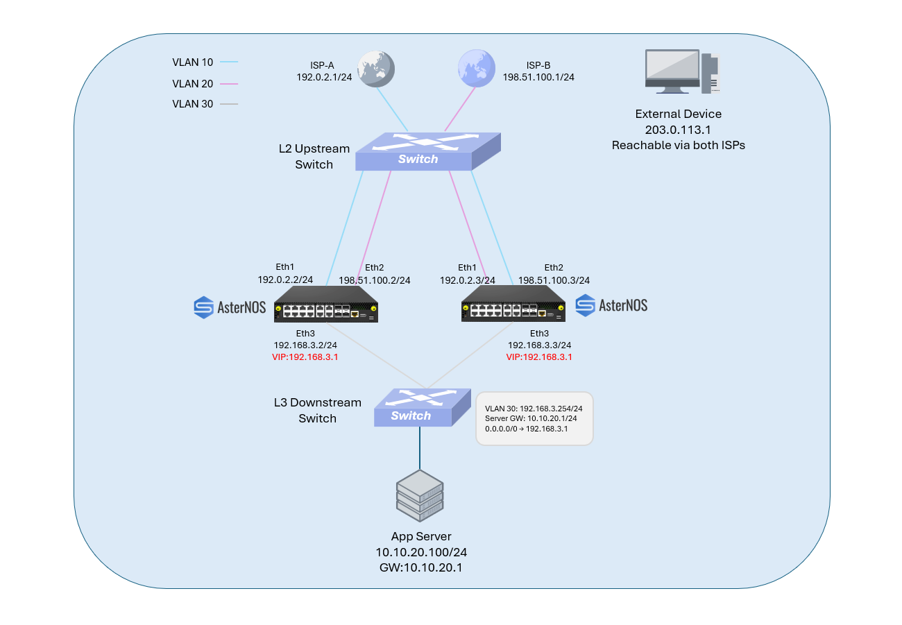
Target Configuration Plan
Section titled “Target Configuration Plan”Router Interface Plan
Section titled “Router Interface Plan”| Router | ISP-A / Ethernet1 | ISP-B / Ethernet2 | LAN / Ethernet3 | Initial VRRP Role |
|---|---|---|---|---|
| Router-A | 192.0.2.2/24 | 198.51.100.2/24 | 192.168.3.2/24 | Master candidate, priority 200 |
| Router-B | 192.0.2.3/24 | 198.51.100.3/24 | 192.168.3.3/24 | Backup candidate, priority 190 |
Shared Network Plan
Section titled “Shared Network Plan”| Network Function | Addressing | Purpose |
|---|---|---|
| ISP-A gateway | 192.0.2.1/24 | Preferred upstream next hop and SLA target |
| ISP-B gateway | 198.51.100.1/24 | Backup upstream next hop |
| LAN VRRP VIP | 192.168.3.1/24 | Stable virtual next hop for the downstream network |
| Downstream transit | 192.168.3.254/24 | Router-facing Layer 3 address |
| Application network | 10.10.20.0/24 | Internal server subnet; gateway 10.10.20.1 |
| App-Server | 10.10.20.100/24 | Internal traffic source |
| External test address | 203.0.113.1/32 | Destination reachable through either ISP |
Infrastructure Prerequisites
Section titled “Infrastructure Prerequisites”Before configuring the routers, ensure that the surrounding network is prepared as follows:
- Router-A Ethernet1 and Router-B Ethernet1 are in the ISP-A Layer 2 domain.
- Router-A Ethernet2 and Router-B Ethernet2 are in the ISP-B Layer 2 domain.
- Router-A Ethernet3 and Router-B Ethernet3 are in the same LAN Layer 2 domain.
- The downstream device routes
10.10.20.0/24toward the application server and uses192.168.3.1as its default route. - The external test address
203.0.113.1/32is reachable through both ISP networks. - The App-Server uses
10.10.20.1as its default gateway.
This guide includes only the Router-A and Router-B configuration commands. The upstream, downstream, and test hosts are treated as preconfigured infrastructure.
Configure Router-A
Section titled “Configure Router-A”sonic# configure
# Set the device hostnamesonic(config)# hostname Router-A
# Create the Monitor Link groupsonic(config)# monitor-link-group ml1 0
# Configure ISP-A as the preferred WANsonic(config)# interface ethernet 1sonic(config-if-1)# ip address 192.0.2.2/24sonic(config-if-1)# monitor-link ml1 uplinksonic(config-if-1)# nat-zone 1sonic(config-if-1)# exit
# Configure ISP-B as the backup WANsonic(config)# interface ethernet 2sonic(config-if-2)# ip address 198.51.100.2/24sonic(config-if-2)# monitor-link ml1 uplinksonic(config-if-2)# nat-zone 1sonic(config-if-2)# exit
# Configure the LAN interface and VRRPsonic(config)# interface ethernet 3sonic(config-if-3)# ip address 192.168.3.2/24sonic(config-if-3)# monitor-link ml1 downlinksonic(config-if-3)# vrrp 1sonic(config-if-3)# vrrp 1 priority 200sonic(config-if-3)# vrrp 1 ip 192.168.3.1/24sonic(config-if-3)# exit
# Enable dynamic NAT and create one pool for each WANsonic(config)# nat enablesonic(config)# nat pool ispa-pool 192.0.2.2sonic(config)# nat pool ispb-pool 198.51.100.2sonic(config)# nat binding ispa-binding ispa-poolsonic(config)# nat binding ispb-binding ispb-pool
# Probe the preferred ISP gatewaysonic(config)# sla 1 icmp-echo dst-ip 192.0.2.1 src-ip 192.0.2.2
# Install the preferred default route only while SLA 1 is healthysonic(config)# track 1sonic(config-track-1)# route 0.0.0.0/0 192.0.2.1 dev Ethernet1sonic(config-track-1)# sla 1sonic(config-track-1)# exit
# Install ISP-B as the backup default routesonic(config)# ip route 0.0.0.0/0 198.51.100.1 20
# Add the return route to the application-server networksonic(config)# ip route 10.10.20.0/24 192.168.3.254
# Save the configurationsonic(config)# endsonic# writeFailover roles:
SLA and Track control WAN route selection within the active router. Monitor Link triggers LAN-side VRRP failover only when all configured WAN uplinks are unavailable.
Configure Router-B
Section titled “Configure Router-B”sonic# configure
# Set the device hostnamesonic(config)# hostname Router-B
# Create the Monitor Link groupsonic(config)# monitor-link-group ml1 0
# Configure ISP-A as the preferred WANsonic(config)# interface ethernet 1sonic(config-if-1)# ip address 192.0.2.3/24sonic(config-if-1)# monitor-link ml1 uplinksonic(config-if-1)# nat-zone 1sonic(config-if-1)# exit
# Configure ISP-B as the backup WANsonic(config)# interface ethernet 2sonic(config-if-2)# ip address 198.51.100.3/24sonic(config-if-2)# monitor-link ml1 uplinksonic(config-if-2)# nat-zone 1sonic(config-if-2)# exit
# Configure the LAN interface and VRRPsonic(config)# interface ethernet 3sonic(config-if-3)# ip address 192.168.3.3/24sonic(config-if-3)# monitor-link ml1 downlinksonic(config-if-3)# vrrp 1sonic(config-if-3)# vrrp 1 priority 190sonic(config-if-3)# vrrp 1 ip 192.168.3.1/24sonic(config-if-3)# exit
# Enable dynamic NAT and create one pool for each WANsonic(config)# nat enablesonic(config)# nat pool ispa-pool 192.0.2.3sonic(config)# nat pool ispb-pool 198.51.100.3sonic(config)# nat binding ispa-binding ispa-poolsonic(config)# nat binding ispb-binding ispb-pool
# Probe the preferred ISP gatewaysonic(config)# sla 1 icmp-echo dst-ip 192.0.2.1 src-ip 192.0.2.3
# Install the preferred default route only while SLA 1 is healthysonic(config)# track 1sonic(config-track-1)# route 0.0.0.0/0 192.0.2.1 dev Ethernet1sonic(config-track-1)# sla 1sonic(config-track-1)# exit
# Install ISP-B as the backup default routesonic(config)# ip route 0.0.0.0/0 198.51.100.1 20
# Add the return route to the application-server networksonic(config)# ip route 10.10.20.0/24 192.168.3.254
# Save the configurationsonic(config)# endsonic# writeVerification
Section titled “Verification”Verification 1: Normal Dynamic NAT Through ISP-A
Section titled “Verification 1: Normal Dynamic NAT Through ISP-A”Check the VRRP and Routing State
Section titled “Check the VRRP and Routing State”Run the following commands:
# Check Router-Asonic# show vrrp summarysonic# show ip route
# Check Router-Bsonic# show vrrp summary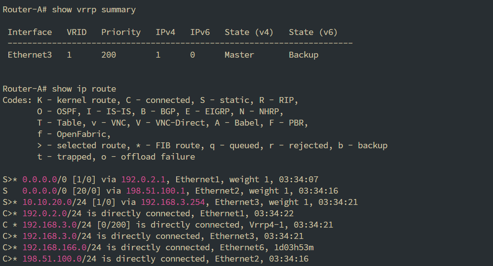

Generate and Verify Outbound Traffic
Section titled “Generate and Verify Outbound Traffic”From App-Server, generate traffic toward the external test address:
app-server$ ping -c 5 203.0.113.1Expected translated packets on the ISP-A path:
192.0.2.2 -> 203.0.113.1 ICMP Echo request203.0.113.1 -> 192.0.2.2 ICMP Echo replyThe source address 192.0.2.2 confirms that Router-A performs dynamic source NAT through ISP-A.

Verification 2: Single-WAN Failover Within Router-A
Section titled “Verification 2: Single-WAN Failover Within Router-A”Trigger the Failure
Section titled “Trigger the Failure”Disconnect Router-A Ethernet1 from the ISP-A network while keeping Router-A Ethernet2 and Ethernet3 available. Wait for the SLA and route tracking state to converge.
Check the Control-Plane Result
Section titled “Check the Control-Plane Result”Run on Router-A:
sonic# show sla briefsonic# show ip routesonic# show vrrp summary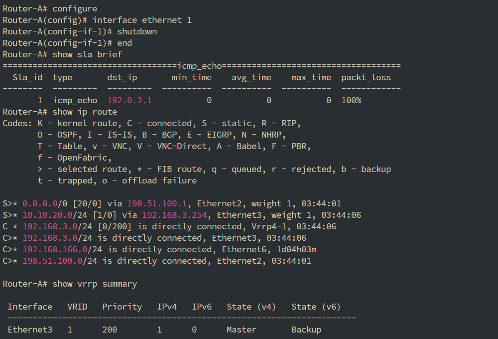
Verify NAT Through ISP-B
Section titled “Verify NAT Through ISP-B”From App-Server, generate traffic toward the same external test address:
app-server$ ping -c 5 203.0.113.1Expected translated packets on the ISP-B path:
198.51.100.2 -> 203.0.113.1 ICMP Echo request203.0.113.1 -> 198.51.100.2 ICMP Echo replyThe translated source address changes from 192.0.2.2 to 198.51.100.2, proving that routing and NAT follow the backup WAN path.

After completing this test, restore Router-A Ethernet1 and confirm that the preferred ISP-A route is active before proceeding.
Verification 3: Router-Level Failover After Dual-WAN Loss
Section titled “Verification 3: Router-Level Failover After Dual-WAN Loss”Trigger the Failure
Section titled “Trigger the Failure”Disconnect Router-A Ethernet1 and Ethernet2 from their upstream networks while keeping Router-A powered on.
Keeping Router-A running ensures that this test validates the combined Monitor Link + VRRP behavior rather than a simple device-power-loss timeout.
Verify Router-B Takeover
Section titled “Verify Router-B Takeover”Run on Router-B:
sonic# show vrrp summarysonic# show ip route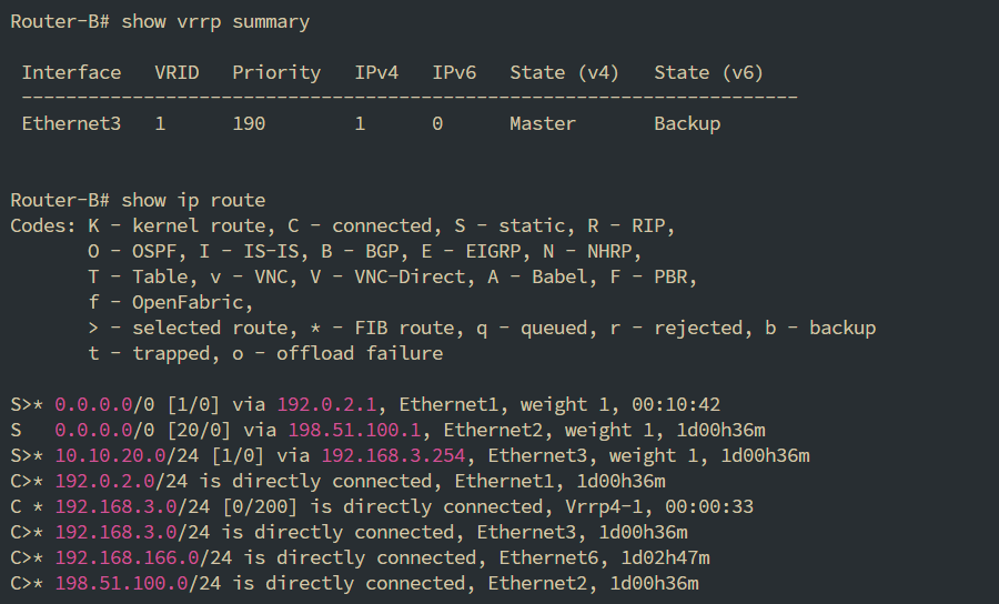
From App-Server, generate new traffic:
app-server$ ping -c 5 203.0.113.1Expected translated packets on Router-B’s ISP-A path:
192.0.2.3 -> 203.0.113.1 ICMP Echo request203.0.113.1 -> 192.0.2.3 ICMP Echo replyThe source address 192.0.2.3 proves that new traffic is now forwarded and translated by Router-B.

Expected behavior:
This scenario validates recovery for new traffic flows. Existing stateful sessions may be interrupted because Router-A and Router-B use different WAN addresses and no HA session synchronization is configured.
Scenario 2: Stateful NAT High Availability with VRRP Sync Group
Section titled “Scenario 2: Stateful NAT High Availability with VRRP Sync Group”Scenario Overview
Section titled “Scenario Overview”Scenario 2 publishes the same internal SSH service through two floating WAN virtual IP addresses and uses a LAN virtual IP as the downstream gateway. All three VRRP instances belong to one Sync Group and move between Router-A and Router-B as a coordinated set.
A dedicated HA link synchronizes the NAT and SPI session state required by the validated TCP flows. The verification covers continuity of established inbound static-NAT and outbound dynamic-NAT SSH sessions during failover. HA Sync also supports LB session synchronization, although LB is not configured or verified in this guide.
Preparation and Environmental Overview
Section titled “Preparation and Environmental Overview”Network Topology Plan
Section titled “Network Topology Plan”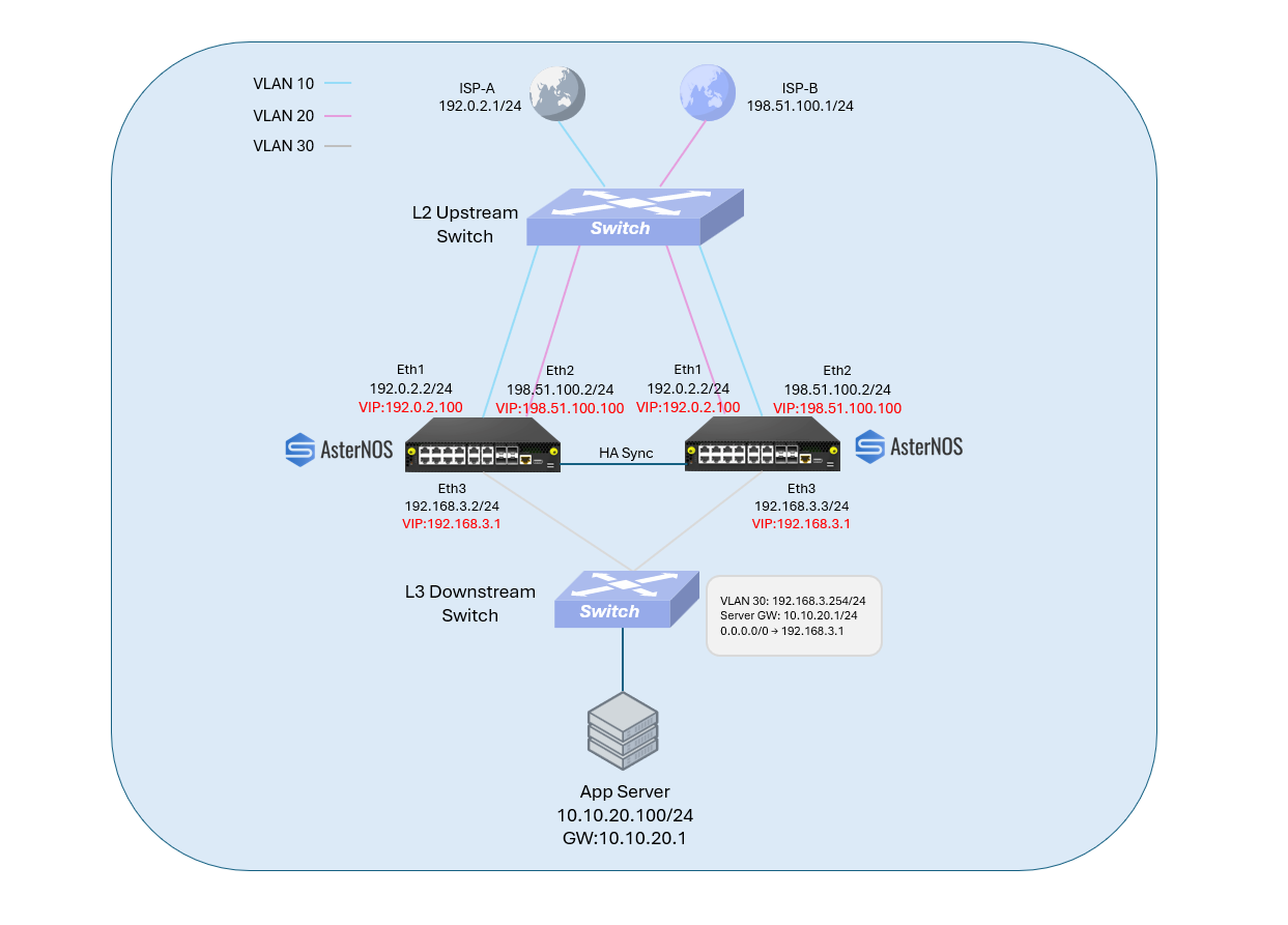
Target Configuration Plan
Section titled “Target Configuration Plan”Router Interface Plan
Section titled “Router Interface Plan”| Router | ISP-A / Ethernet1 | ISP-B / Ethernet2 | LAN / Ethernet3 | HA Sync / Ethernet4 | Initial VRRP Role |
|---|---|---|---|---|---|
| Router-A | 192.0.2.2/24 | 198.51.100.2/24 | 192.168.3.2/24 | 10.255.255.1/30 | Master candidate, priority 200 |
| Router-B | 192.0.2.3/24 | 198.51.100.3/24 | 192.168.3.3/24 | 10.255.255.2/30 | Backup candidate, priority 190 |
Shared Address and Service Plan
Section titled “Shared Address and Service Plan”| Function | Address or Port | Purpose |
|---|---|---|
| ISP-A next hop and test node | 192.0.2.1/24 | ISP-A gateway, SSH server, and external SSH client |
| ISP-B next hop and test node | 198.51.100.1/24 | ISP-B gateway and external SSH client |
| ISP-A WAN VIP | 192.0.2.100 | Floating public service and dynamic NAT address |
| ISP-B WAN VIP | 198.51.100.100 | Floating public service and dynamic NAT address |
| LAN VRRP VIP | 192.168.3.1 | Stable downstream next hop |
| Downstream transit | 192.168.3.254/24 | Router-facing downstream address |
| App-Server | 10.10.20.100/24 | Internal SSH server and outbound test client |
| Published service | WAN VIP TCP 2022 | Translated to 10.10.20.100:22 |
| HA Sync network | 10.255.255.0/30 | Dedicated session synchronization path |
| HA domain ID | 10 | Common HA synchronization domain |
VRRP Sync Group Plan
Section titled “VRRP Sync Group Plan”| Interface | VRID | Virtual IP | Sync Group |
|---|---|---|---|
| Ethernet1 | 2 | 192.0.2.100 | 1 |
| Ethernet2 | 3 | 198.51.100.100 | 1 |
| Ethernet3 | 1 | 192.168.3.1 | 1 |
Infrastructure Prerequisites
Section titled “Infrastructure Prerequisites”Before configuring the routers, ensure that:
- Both routers can reach
192.0.2.1through Ethernet1. - Both routers can reach
198.51.100.1through Ethernet2. - Router-A Ethernet3, Router-B Ethernet3, and the downstream transit interface share the same Layer 2 domain.
- The downstream device routes
10.10.20.0/24and uses192.168.3.1as its default route. - App-Server uses
10.10.20.1as its default gateway. - App-Server is configured as
10.10.20.100/24and SSH is listening on TCP port22. - The ISP-A test node can accept SSH connections when outbound dynamic NAT continuity is tested.
- Router-A Ethernet4 is directly connected to Router-B Ethernet4.
- The WAN and HA networks are isolated from one another.
This guide includes only the Router-A and Router-B configuration commands. The ISP test nodes, downstream device, and App-Server are treated as preconfigured infrastructure.
Deployment notes:
HA Sync synchronizes supported runtime session state; it does not synchronize device configuration. Router-A and Router-B must use consistent VRRP Sync Group, NAT, SPI, PBR, and routing configurations. In this validated scenario, failover is triggered by a VRRP Sync Group member interface state change. SLA and Track do not change VRRP ownership; loss of upstream reachability without a corresponding local interface-down event does not trigger the demonstrated failover.
Session reset when enabling TCP SPI:
Enabling TCP Stateful Packet Inspection on either router clears its existing TCP session state. Establish the validation sessions only after TCP SPI has been enabled on both routers.
Configure Router-A
Section titled “Configure Router-A”sonic# configure
# Set the device hostnamesonic(config)# hostname Router-A
# Configure ISP-A and its VRRP membersonic(config)# interface ethernet 1sonic(config-if-1)# ip address 192.0.2.2/24sonic(config-if-1)# nat-zone 1sonic(config-if-1)# vrrp 2sonic(config-if-1)# vrrp 2 priority 200sonic(config-if-1)# vrrp 2 preemptsonic(config-if-1)# vrrp 2 sync-group 1 priority-dec 20sonic(config-if-1)# vrrp 2 ip 192.0.2.100/24sonic(config-if-1)# exit
# Configure ISP-B and its VRRP membersonic(config)# interface ethernet 2sonic(config-if-2)# ip address 198.51.100.2/24sonic(config-if-2)# nat-zone 1sonic(config-if-2)# vrrp 3sonic(config-if-2)# vrrp 3 priority 200sonic(config-if-2)# vrrp 3 preemptsonic(config-if-2)# vrrp 3 sync-group 1 priority-dec 20sonic(config-if-2)# vrrp 3 ip 198.51.100.100/24sonic(config-if-2)# exit
# Configure the LAN interface and bind the return-path policysonic(config)# interface ethernet 3sonic(config-if-3)# ip address 192.168.3.2/24sonic(config-if-3)# vrrp 1sonic(config-if-3)# vrrp 1 priority 200sonic(config-if-3)# vrrp 1 preemptsonic(config-if-3)# vrrp 1 sync-group 1 priority-dec 20sonic(config-if-3)# vrrp 1 ip 192.168.3.1/24sonic(config-if-3)# exit
# Configure the dedicated HA synchronization linksonic(config)# interface ethernet 4sonic(config-if-4)# ip address 10.255.255.1/30sonic(config-if-4)# exit
# Enable NAT and publish the internal SSH service through both WAN VIPssonic(config)# nat enablesonic(config)# nat static tcp 192.0.2.100 2022 10.10.20.100 22 dnat extendable ispa-sshsonic(config)# nat static tcp 198.51.100.100 2022 10.10.20.100 22 dnat extendable ispb-ssh
# Use the floating WAN addresses for dynamic outbound NATsonic(config)# nat pool ispa-pool 192.0.2.100sonic(config)# nat pool ispb-pool 198.51.100.100sonic(config)# nat binding ispa-binding ispa-poolsonic(config)# nat binding ispb-binding ispb-pool
# Configure the normal and backup default routessonic(config)# ip route 0.0.0.0/0 192.0.2.1sonic(config)# ip route 0.0.0.0/0 198.51.100.1 20sonic(config)# ip route 10.10.20.0/24 192.168.3.254
# Preserve symmetric return routing for connections received through ISP-Asonic(config)# pbr-map ha-pbr seq 10sonic(config-pbr-ha-pbr-10)# match src-ip 10.10.20.0/24sonic(config-pbr-ha-pbr-10)# set nexthop 192.0.2.1sonic(config-pbr-ha-pbr-10)# src_interface 1sonic(config-pbr-ha-pbr-10)# exit
# Preserve symmetric return routing for connections received through ISP-Bsonic(config)# pbr-map ha-pbr seq 20sonic(config-pbr-ha-pbr-20)# match src-ip 10.10.20.0/24sonic(config-pbr-ha-pbr-20)# set nexthop 198.51.100.1sonic(config-pbr-ha-pbr-20)# src_interface 2sonic(config-pbr-ha-pbr-20)# exit
sonic(config)# interface ethernet 3sonic(config-if-3)# pbr-policy ha-pbrsonic(config-if-3)# exit# Enable TCP state trackingsonic(config)# stateful-packet-inspection enable tcp
# Configure HA session synchronizationsonic(config)# ha_sync enablesonic(config)# ha_sync globalsonic(config-ha-sync)# domain_id 10sonic(config-ha-sync)# peer_address 10.255.255.2sonic(config-ha-sync)# src_address 10.255.255.1sonic(config-ha-sync)# src_intfc ethernet 4sonic(config-ha-sync)# exit
# Save the configurationsonic(config)# endsonic# writeConfigure Router-B
Section titled “Configure Router-B”sonic# configure
# Set the device hostnamesonic(config)# hostname Router-B
# Configure ISP-A and its VRRP membersonic(config)# interface ethernet 1sonic(config-if-1)# ip address 192.0.2.3/24sonic(config-if-1)# nat-zone 1sonic(config-if-1)# vrrp 2sonic(config-if-1)# vrrp 2 priority 190sonic(config-if-1)# vrrp 2 preemptsonic(config-if-1)# vrrp 2 sync-group 1 priority-dec 20sonic(config-if-1)# vrrp 2 ip 192.0.2.100/24sonic(config-if-1)# exit
# Configure ISP-B and its VRRP membersonic(config)# interface ethernet 2sonic(config-if-2)# ip address 198.51.100.3/24sonic(config-if-2)# nat-zone 1sonic(config-if-2)# vrrp 3sonic(config-if-2)# vrrp 3 priority 190sonic(config-if-2)# vrrp 3 preemptsonic(config-if-2)# vrrp 3 sync-group 1 priority-dec 20sonic(config-if-2)# vrrp 3 ip 198.51.100.100/24sonic(config-if-2)# exit
# Configure the LAN interface and bind the return-path policysonic(config)# interface ethernet 3sonic(config-if-3)# ip address 192.168.3.3/24sonic(config-if-3)# vrrp 1sonic(config-if-3)# vrrp 1 priority 190sonic(config-if-3)# vrrp 1 preemptsonic(config-if-3)# vrrp 1 sync-group 1 priority-dec 20sonic(config-if-3)# vrrp 1 ip 192.168.3.1/24sonic(config-if-3)# exit
# Configure the dedicated HA synchronization linksonic(config)# interface ethernet 4sonic(config-if-4)# ip address 10.255.255.2/30sonic(config-if-4)# exit
# Enable NAT and install the same static service mappingssonic(config)# nat enablesonic(config)# nat static tcp 192.0.2.100 2022 10.10.20.100 22 dnat extendable ispa-sshsonic(config)# nat static tcp 198.51.100.100 2022 10.10.20.100 22 dnat extendable ispb-ssh
# Use the floating WAN addresses for dynamic outbound NATsonic(config)# nat pool ispa-pool 192.0.2.100sonic(config)# nat pool ispb-pool 198.51.100.100sonic(config)# nat binding ispa-binding ispa-poolsonic(config)# nat binding ispb-binding ispb-pool
# Configure the normal and backup default routessonic(config)# ip route 0.0.0.0/0 192.0.2.1sonic(config)# ip route 0.0.0.0/0 198.51.100.1 20sonic(config)# ip route 10.10.20.0/24 192.168.3.254
# Preserve symmetric return routing for connections received through ISP-Asonic(config)# pbr-map ha-pbr seq 10sonic(config-pbr-ha-pbr-10)# match src-ip 10.10.20.0/24sonic(config-pbr-ha-pbr-10)# set nexthop 192.0.2.1sonic(config-pbr-ha-pbr-10)# src_interface 1sonic(config-pbr-ha-pbr-10)# exit
# Preserve symmetric return routing for connections received through ISP-Bsonic(config)# pbr-map ha-pbr seq 20sonic(config-pbr-ha-pbr-20)# match src-ip 10.10.20.0/24sonic(config-pbr-ha-pbr-20)# set nexthop 198.51.100.1sonic(config-pbr-ha-pbr-20)# src_interface 2sonic(config-pbr-ha-pbr-20)# exit
sonic(config)# interface ethernet 3sonic(config-if-3)# pbr-policy ha-pbrsonic(config-if-3)# exit# Enable TCP state trackingsonic(config)# stateful-packet-inspection enable tcp
# Configure HA session synchronizationsonic(config)# ha_sync enablesonic(config)# ha_sync globalsonic(config-ha-sync)# domain_id 10sonic(config-ha-sync)# peer_address 10.255.255.1sonic(config-ha-sync)# src_address 10.255.255.2sonic(config-ha-sync)# src_intfc ethernet 4sonic(config-ha-sync)# exit
# Save the configurationsonic(config)# endsonic# writeVerification
Section titled “Verification”Static NAT Through Both WAN VIPs
Section titled “Static NAT Through Both WAN VIPs”From the ISP-A test node, connect to the App-Server through the ISP-A WAN VIP:
isp-a$ ssh -p 2022 <username>@192.0.2.100From the ISP-B test node, connect to the same App-Server through the ISP-B WAN VIP:
isp-b$ ssh -p 2022 <username>@198.51.100.100Expected result:
- Both SSH sessions are established successfully.
Initial VRRP Sync Group State
Section titled “Initial VRRP Sync Group State”Before triggering the failover, check the VRRP state on both routers:
# Check Router-ARouter-A# show vrrp summary
# Check Router-BRouter-B# show vrrp summary
Expected initial state:
| Router | Ethernet1 / VRID 2 | Ethernet2 / VRID 3 | Ethernet3 / VRID 1 |
|---|---|---|---|
| Router-A | Master | Master | Master |
| Router-B | Backup | Backup | Backup |


WAN-to-LAN Session Continuity
Section titled “WAN-to-LAN Session Continuity”Establish the SSH Session
Section titled “Establish the SSH Session”From the ISP-B test node, connect to the App-Server through the ISP-B WAN VIP:
isp-b$ ssh -p 2022 <username>@198.51.100.100Confirm that the SSH session is stable before triggering the failover. Keep the session open.
Trigger the Sync Group Failover
Section titled “Trigger the Sync Group Failover”On Router-A, shut down Ethernet1:
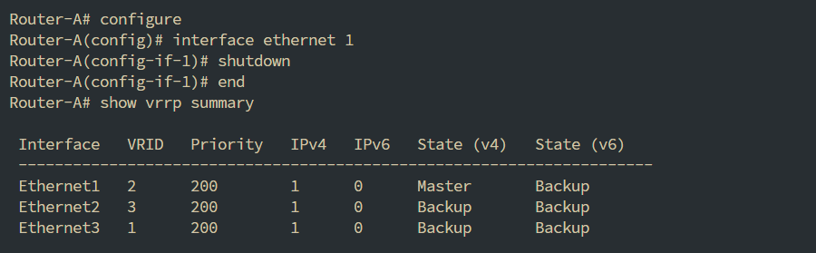
Router-A# configureRouter-A(config)# interface ethernet 1Router-A(config-if-1)# shutdownRouter-A(config-if-1)# exitRouter-A(config)# endEthernet1 carries VRID 2, which is a member of Sync Group 1. Its failure causes the remaining WAN and LAN VRRP members to move to Router-B as one coordinated group.
Verify the VRRP State
Section titled “Verify the VRRP State”Run the following commands after the state has converged:
# Check Router-ARouter-A# show vrrp summary
# Check Router-BRouter-B# show vrrp summary
Expected result:
| Router | Ethernet1 / VRID 2 | Ethernet2 / VRID 3 | Ethernet3 / VRID 1 |
|---|---|---|---|
| Router-A | Master | Backup | Backup |
| Router-B | Master | Master | Master |
Router-B should become Master for both WAN VIPs and the LAN VIP.
On Router-A:
- Ethernet2 and Ethernet3 should no longer remain active Master members.
- Ethernet1 may still display
Masterinshow vrrp summaryafter the interface has been shut down.
The displayed state of the administratively down interface may not be refreshed after it loses connectivity. This does not mean that Router-A still actively owns or advertises the Ethernet1 virtual IP. Router-B becoming Master for VRID 2 is the effective takeover result.

Verify Session Continuity
Section titled “Verify Session Continuity”Return to the SSH session that was established through:
198.51.100.100:2022Expected result:
- The existing SSH session remains connected.
- A brief pause may occur during the VRRP transition.
- The user is not required to reconnect or authenticate again.
LAN-to-WAN Session Continuity
Section titled “LAN-to-WAN Session Continuity”Restore the Initial VRRP State
Section titled “Restore the Initial VRRP State”Restore Router-A Ethernet1:
Router-A# configureRouter-A(config)# interface ethernet 1Router-A(config-if-1)# no shutdownRouter-A(config-if-1)# exitRouter-A(config)# endAfter the VRRP state stabilizes, confirm that Router-A has recovered the Master role:
Router-A# show vrrp summaryRouter-B# show vrrp summaryExpected state:
| Router | Ethernet1 / VRID 2 | Ethernet2 / VRID 3 | Ethernet3 / VRID 1 |
|---|---|---|---|
| Router-A | Master | Master | Master |
| Router-B | Backup | Backup | Backup |
Establish the Outbound SSH Session
Section titled “Establish the Outbound SSH Session”From App-Server, connect to the ISP-A test node:
app-server$ ssh <username>@192.0.2.1Confirm that the SSH session is stable before triggering the failover. Keep the session open.
This connection is initiated from the LAN and is dynamically translated through the ISP-A WAN VIP.
Trigger the Sync Group Failover
Section titled “Trigger the Sync Group Failover”Shut down Router-A Ethernet1 again:
Router-A# configureRouter-A(config)# interface ethernet 1Router-A(config-if-1)# shutdownRouter-A(config-if-1)# exitRouter-A(config)# endVerify the VRRP state:
Router-A# show vrrp summaryRouter-B# show vrrp summaryExpected result:
| Router | Ethernet1 / VRID 2 | Ethernet2 / VRID 3 | Ethernet3 / VRID 1 |
|---|---|---|---|
| Router-A | Master | Backup | Backup |
| Router-B | Master | Master | Master |
Verify Session Continuity
Section titled “Verify Session Continuity”Return to the SSH session initiated from App-Server to 192.0.2.1.
Expected result:
- The existing SSH session remains connected.
- A brief pause may occur while the VRRP Sync Group changes ownership.
- The user is not required to reconnect.
Recovery
Section titled “Recovery”Restore Router-A Ethernet1:
Router-A# configureRouter-A(config)# interface ethernet 1Router-A(config-if-1)# no shutdownRouter-A(config-if-1)# exitRouter-A(config)# endVerify the VRRP state:
Router-A# show vrrp summaryRouter-B# show vrrp summaryBecause Router-A has the higher priority and preemption is enabled on every member, the expected recovered state is:
| Router | Ethernet1 / VRID 2 | Ethernet2 / VRID 3 | Ethernet3 / VRID 1 |
|---|---|---|---|
| Router-A | Master | Master | Master |
| Router-B | Backup | Backup | Backup |
Conclusion
Section titled “Conclusion”This guide has successfully demonstrated the comprehensive high-availability (HA) capabilities of the AsterNOS-VPP edge gateway. By walking through two distinct, enterprise-grade deployment scenarios, we have validated the system’s ability to deliver both link-level redundancy and seamless device-level resiliency.
- In Scenario 1, we built a robust dual-WAN routing architecture. By integrating dynamic NAT, SLA-based route tracking, and Monitor Link, the gateway ensures continuous outbound Internet access, intelligently routing around ISP failures and seamlessly transferring the LAN virtual gateway to a standby device when necessary.
- In Scenario 2, we elevated the architecture to support stateful session synchronization. Through the implementation of a VRRP Sync Group, policy-based return routing (PBR), and dedicated HA data links, AsterNOS-VPP successfully preserved established TCP connections—for both inbound published services and outbound dynamic NAT—during a complete device failover.
Together, these validated configurations confirm that AsterNOS-VPP is fully equipped to serve as a secure, uninterrupted, and highly reliable edge gateway, ensuring maximum uptime and seamless service delivery for mission-critical enterprise networks.