
Intelligent Lossless Network Configuration Guide
Static Intelligent Routing
Section titled “Static Intelligent Routing”In an AI intelligent computing network with an uplink and downlink bandwidth of 1:1, complex scenarios with multiple ingresses and multiple egresses are often encountered. In such scenarios, we hope to evenly distribute traffic with the same destination from multiple ingresses to multiple egresses while maintaining the order of data packets, that is, forwarding them flow by flow. However, in actual environments, traffic from multiple inlets often converges to one outlet, while there is no traffic on other outlets, resulting in unbalanced load sharing and network congestion. In response to this problem, Asterfusion proposed an intelligent routing algorithm that allocates VRFs based on source IP addresses, implements service isolation through VRFs, and forwards traffic based on policy routing, eliminating the traditional hash process to solve the problem of uneven load.
Static Intelligent Routing Workflow
Section titled “Static Intelligent Routing Workflow”- Routing learning process
- Local Leaf: After the tenant comes online, the local Leaf generates host routes under the default VRF of the downstream Server directly connected to the NIC through the ARP to host function, generates host routes under the VRF according to the IPs and tenant VRFs, and carries the tag to announce to the remote end.
- Spine: Spine receives the host route with the specified tag and generates a normal route locally and synchronizes it to the peer Leaf.
- Peer Leaf: When the peer Leaf receives the host route information with the specified tag, it generates the host/prefix route under the corresponding tenant VRF locally (the default VRF route is imported through tag filtering), and when the route status is Action, it will additionally be assigned with the tenant VRF route table hit information for the following policy route forwarding.
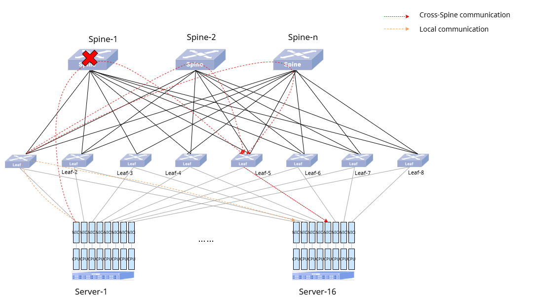
- Forwarding process According to the flow forwarding path, the flow forwarding model can be classified into local communication forwarding and cross-Spine communication forwarding as shown in the following figure:
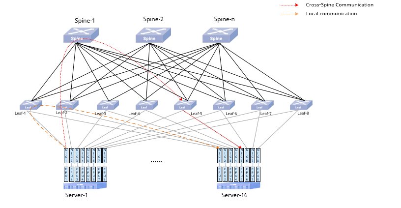
For the two types of communication forwarding, the specific processing flow of the device is as follows: (1) Local communication Forwarding path: traffic is sent from NIC1 of Server-1 to NIC1 of Server-16. After Leaf-1 receives the traffic sent from NIC1 of Server-1, it assigns VRF according to the source IP, queries the routing table of the corresponding VRF for guided forwarding, and finds that the destination IP belongs to NIC1 of Server-16, hits the local routing table, and forwards it to the destination NIC (NIC1 of Server-16) directly according to the next hop of the route. (2) Traffic path: traffic is sent from NIC1 of Server-1 to NIC5 of Server-16.
- After Leaf-1 receives the traffic sent from Server-1 NIC1, it assigns VRFs according to the source IP, queries the routing table of the corresponding VRFs, and finds that the destination IP belongs to NIC5 of Server-16, hits the remote routing table, and the destination IP is in the downlink ip-list of the opposite end. Then determine the corresponding policy route according to the routes of the source IP and the VRF where the tenant is located, and redirect to the specified next hop according to this policy route; finally, enter the Spine for forwarding according to the uplink interface corresponding to the next hop.
- Spine receives the traffic and queries the routing table for forwarding according to the standard L3 logic.
- Leaf-5 receives the traffic and forwards it to the destination NIC according to the default routing table.
Link Failure Handling
Section titled “Link Failure Handling”- Uplink Failure
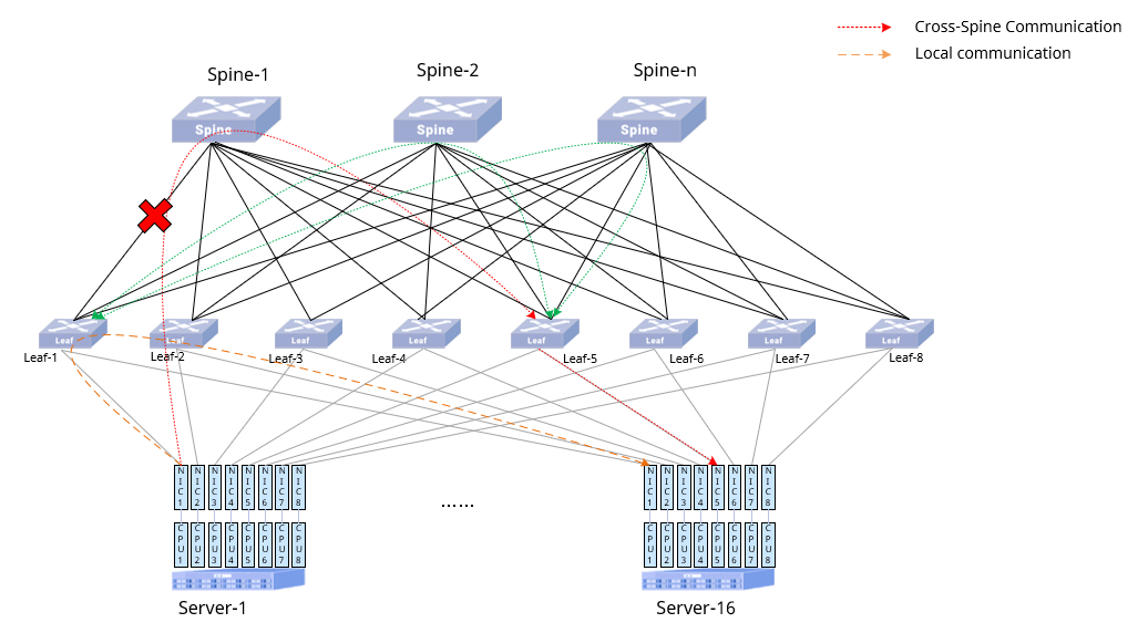
Processing flow of the device in case of uplink failure and recovery:
- If the link between Leaf-1 and Spine-1 fails, Leaf-1 senses the link failure, the policy route corresponding to the failed link is invalid, and the corresponding traffic goes through ECMP (Spine-2+Spine-3+…+ Spine-n), and the other traffic other traffic is still forwarded through the corresponding policy route.
- Other Leaf senses the change of the remote route, and the corresponding next hop is reduced from n Spines to (n-1) Spines causing its number to be less than the number of ports in the uplink list, then the policy route fails for the remote route, and then the corresponding next hop of the route is changed to ECMP (Spine-2+Spine-3+ …+ Spine-n), and other traffic is not affected.
- After the link is restored, Leaf-1 redistributes the corresponding policy route, and the corresponding traffic is restored to be forwarded according to the policy route.
- When other leafs sense the change of the corresponding remote route, the corresponding next hop is increased from (n-1) spines to n spines, and the number of next hops is greater than or equal to the number of ports in the uplink list, the policy route for the remote route takes effect, and it is restored from forwarding in accordance with ECMP to forwarding in accordance with the policy route.
- Spine Failure
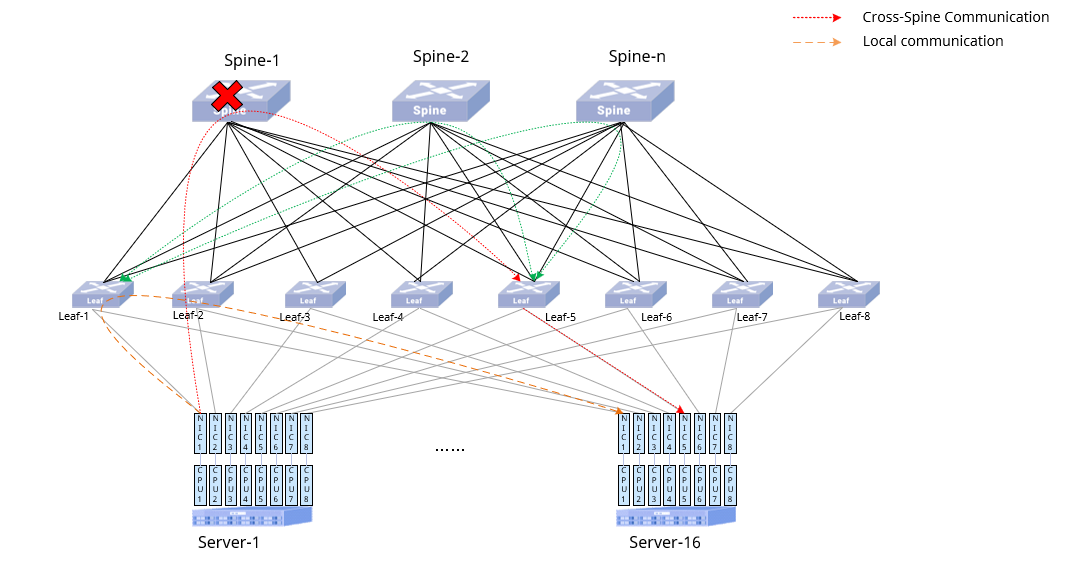
Device Handling Process During Spine Failure and Recovery:
- Spine Failure When a Spine fails, all Leaf devices detect that the number of next hops for all remote routes decreases from n Spines to (n-1) Spines. If the number of next hops is less than the configured number of ports in the uplink list, the policy-based routing for remote routes becomes invalid. Traffic forwarding then switches from policy-based routing to regular ECMP (Equal-Cost Multi-Path). In this failure scenario, traffic is forwarded using standard ECMP, so it is recommended to combine this with enhanced hash mechanisms.
- Spine Recovery After a Spine recovers, all Leaf devices detect that the number of next hops for all remote routes increases from (n-1) Spines back to n Spines. If the number of next hops meets or exceeds the configured number of ports in the uplink list, policy-based routing for remote routes is restored. Traffic forwarding then switches back from ECMP to policy-based routing.
Dynamic Intelligent Routing
Section titled “Dynamic Intelligent Routing”Three mainstream technologies currently dominate network load balancing: Flow-based ECMP (Equal-Cost Multi-Path) balancing, flowlet-based subflow balancing, and Packet-based ECMP balancing.
- Flow-based ECMP Balancing The most widely used load balancing algorithm leverages 5-tuple flow hashing. It performs well in scenarios with numerous flow connections, offering the advantage of zero packet reordering. However, it suffers from hash collisions in flow-sparse environments (e.g., AI training), leading to suboptimal load distribution.
- Flowlet-Based Subflow Balancing This technique relies on configuring the inter-flowlet time gap (GAP) for load balancing. Accurate GAP configuration becomes unfeasible if global path-level latency information is unavailable in the network.
- Packet-based ECMP Balancing Theoretically optimal for balancing granularity, but causes severe packet reordering issues at the receiver in practice. Dynamic Intelligent Routing is a sensing-driven load balancing technology. By detecting path quality through switches in the network, it dynamically adjusts local switch path selection to achieve flexible load balancing. It further supports dynamic weighted load balancing and introduces the Dynamic WCMP (Weighted Cost Multipath) algorithm by enhancing flow-based ECMP. Given that data centers and carriers predominantly use BGP as the underlying routing protocol, Dynamic Intelligent Routing extends BGP by defining a new extended community attribute. This attribute evaluates path quality based on multi-dimensional high-precision metrics, transmitted via BGP to guide traffic forwarding—improving overall load balancing efficiency and reducing application response time.
Path Quality Synchronization and Calculation
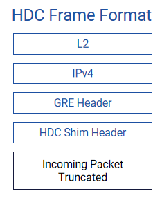
Section titled “Path Quality Synchronization and Calculation”Based on long-term observations in AI cluster networks, Dynamic Intelligent Routing incorporates critical parameters (bandwidth utilization, queue occupancy, and forwarding latency) as factors for comprehensive path quality assessment. Bandwidth/Queue Utilization: Collected from ASIC hardware registers with hundred-millisecond accuracy. Results are announced via BGP at 1-second intervals (weighted averaging prioritizes recent data) to reduce control-plane overhead. Forwarding Latency: Measured via HDC (High Delay Capture), an INT (In-Band Network Telemetry) technology that captures packets exceeding user-defined latency thresholds. Switches extract the first 150 bytes of such packets with metadata (ingress/egress ports, latency) and send them to collectors for high-precision latency analysis.
Path quality is propagated using the Path Bandwidth Extended Community attribute via BGP extensions. The synchronization logic is illustrated below:
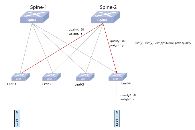
When NIC1 communicates with NIC2, NIC2 first advertises its IP to Leaf2. Leaf2 then advertises NIC2’s IP to the Spine while appending the corresponding link quality (calculated as the link quality toward NIC2 multiplied by Leaf2’s downlink weight). The Spine subsequently advertises NIC2’s IP to Leaf1, appending the corresponding link quality (calculated as the link quality toward Leaf2 multiplied by the Spine’s weight plus the accumulated path metric already carried in the routing information). Finally, Leaf1 aggregates the path quality and generates routing instructions to guide traffic forwarding.
WCMP (Weighted Cost Multipath) forwards traffic proportionally across paths, with ECMP as a special case. In Dynamic Intelligent Routing, WCMP dynamically adjusts route weights based on real-time path quality to achieve flexible load balancing.
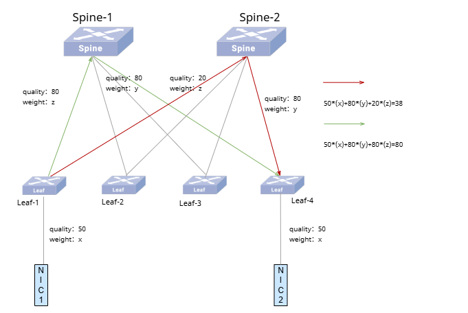
As shown above, when two paths exist between NIC1 and NIC2, assume Leaf1 calculates the comprehensive quality of the red path to NIC2 as 38 and the green path as 80 through path quality synchronization and computation algorithms. The WCMP provisioning then assigns a 3:7 weight ratio (30%:70%) to these paths. As global network traffic fluctuates, path quality dynamically changes. These updates are converted into path quality metrics, propagated via BGP to every Leaf switch, where dynamic WCMP routes are generated to guide traffic forwarding.
Dynamic Routing Workflow
Section titled “Dynamic Routing Workflow”- Route Learning Process
- Local Leaf: Generates Default VRF routes for directly connected NICs (via ARP or BGP). Tags routes with path quality and advertises to remote devices.
- Spine: Receives tagged routes, accumulates local path quality, and synchronizes routes to peer Leaf switches.
- Peer Leaf: Imports routes into tenant VRF (filtered by tags). For multi-path destinations, aggregates path quality and generates WCMP routes.
- Traffic Forwarding Process According to the flow forwarding path, the flow forwarding model can be classified into local communication forwarding and cross-Spine communication forwarding as shown in the following figure:
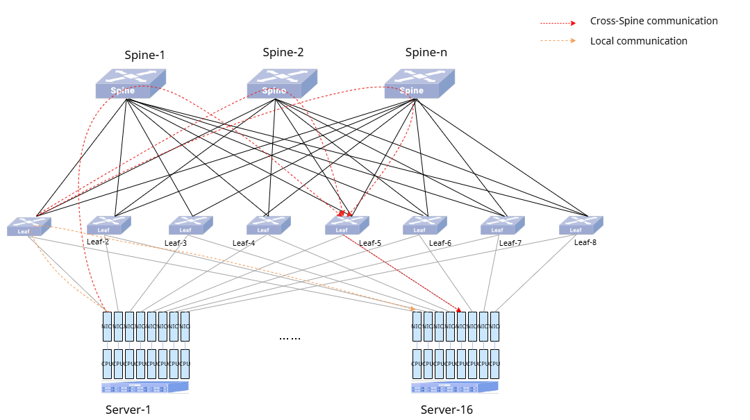
For the two types of communication forwarding, the specific processing flow of the device is as follows:
(1) Local communication Forwarding path: traffic is sent from NIC1 of Server-1 to NIC1 of Server-16 After Leaf-1 receives the traffic sent from NIC1 of Server-1, it assigns VRF based on the source IP, queries the routing table of the corresponding VRF for guided forwarding, and finds that the destination IP belongs to NIC1 of Server-16, hits the local routing table, and forwards it to the destination NIC (NIC1 of Server-16) directly according to the next hop of the route. (2) Cross-Spine Communication Forwarding path: traffic is sent from NIC1 of Server-1 to NIC5 of Server-16
- Leaf-1 assigns VRF, matches the remote route, and distributes traffic to Spines via WCMP weights.
- Spine forwards traffic using standard L3 routing.
- Leaf-5 delivers traffic to the destination NIC via its default route table.
Link Failure Handling
Section titled “Link Failure Handling”- Uplink Failure
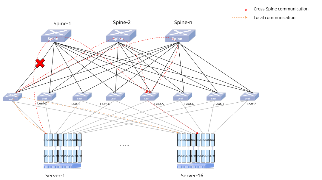
Device Handling Process During Uplink Failure and Recovery
- If the link between Leaf-1 and Spine-1 fails, Leaf-1 detects the failure and withdraws corresponding routes. Traffic continues via WCMP (Spine-2 + Spine-3 + … + Spine-n).
- Other Leaf switches detect the route withdrawal. Traffic destined for Leaf-1 continues via WCMP (Spine-2 + Spine-3 + … + Spine-n).
- After link recovery, Leaf-1 re-advertises routes via BGP, restoring full-path WCMP for affected traffic.
- Other Leaf switches relearn Leaf-1’s routes, restoring full-path WCMP.
- Spine Failure
Device Handling Process During Spine Failure and Recovery
- When Spine-1 fails, all Leaf switches detect withdrawal of routes passing through Spine-1. Traffic continues via WCMP (Spine-2 + Spine-3 + … + Spine-n).
- After Spine-1 recovers, all Leaf switches relearn routes through Spine-1, restoring full-path WCMP.
Intelligent Routing Configuration
Section titled “Intelligent Routing Configuration”Intelligent Routing Default Setting
Section titled “Intelligent Routing Default Setting”The default setting of intelligent routing is shown in the table below.
Table 1 Default setting of Intelligent Routing
| Parameters | Default value |
|---|---|
| router-type | leaf |
| AI-Network mode | Static |
Configure intelligent routing Mode
Section titled “Configure intelligent routing Mode”Table 2 Configure Intelligent Routing Mode
| Purpose | Command | Description |
|---|---|---|
| Enter global configuration view | configure terminal | - |
| Configure Router BGP and enter the appropriate configuration view | router bgp asn | asn: local AS number |
| Disable the ebgp policy requirement | no bgp ebgp-requires-policy | - |
| Return to global configuration view | exit | - |
| Configure device roles | router-type {leaf|spine} | - |
| Configure intelligent routing mode | ai-network mode {static|dynamic} | - |
Configure Leaf Uplink
Section titled “Configure Leaf Uplink”The BGP configuration supports two modes:
- BGP-link-local mode: The device automatically configures BGP neighbors using the IPv6 link-local addresses of the interfaces.
- BGP-normal mode: This mode directly uses the BGP configuration of the uplink interfaces. Therefore, BGP neighbors must be manually configured on the uplink interfaces before enabling this mode.
BGP-link-local mode is simpler to configure and is recommended. The uplink mode must be consistent between Spine and Leaf devices. The following sections detail the uplink configuration steps for each mode:
BGP-link-local mode
Table 3 Leaf Uplink Configuration in bgp-link-local Mode
| Purpose | Command | Description |
|---|---|---|
| Enter global configuration view | configure terminal | - |
| Configure the uplink interface for intelligent routing | ai-network uplink-list {interface-list|default} | interface-list : interface list, the interface needs to be a physical Layer 3 port.default: Top half of front panel ports. |
| Configure uplink bgp mode for intelligent routing | ai-network uplink bgp-link-local | - |
BGP-normal mode
Table 4 Leaf Uplink Configuration in bgp-normal Mode
| Purpose | Command | Description |
|---|---|---|
| Enter global configuration view | configure terminal | - |
| Configure Router BGP and enter the appropriate configuration view | router bgp asn | asn: local AS number |
| Configure BGP neighbor | neighbor neighbor_ip remote-as asn | neighbor_ip: IP address of the BGP neighborasn: neighbor AS number |
| Return to global configuration view | exit | - |
| Configure the uplink interface for intelligent routing | ai-network uplink-list {interface-list|default} | interface-list: interface list, the interface needs to be a physical Layer 3 port.default: Bottom half of front panel ports. |
| Configure uplink BGP mode for intelligent routing | ai-network uplink bgp-link-local | - |
Configure Spine downlink
Section titled “Configure Spine downlink”The following sections detail the uplink configuration steps for each mode:
bgp-link-local mode
Table 5 Spine Downlink Configuration in bgp-link-local Mode
| Purpose | Command | Description |
|---|---|---|
| Enter global configuration view | configure terminal | - |
| Configure the downlink interface for intelligent routing | ai-network downlink-list {interface-list|default} | interface-list : interface list, the interface needs to be a physical Layer 3 port.default: Bottom half of front panel ports. |
| Configure downlink bgp mode for intelligent routing | ai-network downlink bgp-link-local | - |
bgp-normal mode
Table 6 Spine Downlink Configuration in bgp-normal Mode
| Purpose | Command | Description |
|---|---|---|
| Enter global configuration view | configure terminal | - |
| Configure Router BGP and enter the appropriate configuration view | router bgp asn | asn: local AS number |
| Configure BGP neighbor | neighbor neighbor_ip remote-as asn | neighbor_ip: IP address of the BGP neighborasn: neighbor AS number |
| Return to global configuration view | exit | - |
| Configure the downlink interface for intelligent routing | ai-network downlink-list {interface-list|default} | interface-list: interface list, the interface needs to be a physical Layer 3 port.default: Bottom half of front panel ports. |
| Configure downlink BGP mode for intelligent routing | ai-network downlink bgp-link-local | - |
Configure Leaf downlink
Section titled “Configure Leaf downlink”The downlink routing supports two modes: ARP mode is simpler to configure, BGP mode is suitable for scenarios where dynamic route exchange between Leaf devices and servers is required. Therefore, ARP mode is recommended in the absence of specific business requirements.
- ARP mode: Converts ARP entries on the downlink interfaces into host routes and advertises them via the uplink BGP. The configured IP list must be in the same subnet as the downlink interface IP.
- BGP mode: Requires BGP peering between the Leaf device and servers. The Leaf advertises server-learned BGP routes to other Leaf devices via uplink BGP.
Configuration Steps for Both Modes:
ARP Mode
Table 7 Leaf Downlink Configuration in ARP Mode
| Purpose | Command | Description |
|---|---|---|
| Enter global configuration view | configure terminal | - |
| Create an instance of Intelligent Routing Downlink and enter the instance configuration view | ai-network instance instance-id | instance-id: instance ID, range 1-1024 |
| Configure the downlink interface for intelligent routing | downlink-list {interface-list|default} | interface-list: interface list, the interface needs to be a physical Layer 3 port.default: default interface configuration, half of the ports below the front panel |
| Configure the routing mode of intelligent routing downlink and enter the corresponding configuration view. | downlink-mode arp | arp: ARP mode |
| Configure intelligent routing downlink IP list | ip-list ip-list | ip-list: interface routing list, only supports 32 bits |
BGP Mode
Table 8 Leaf Downlink Configuration in BGP Mode
| Purpose | Command | Description |
|---|---|---|
| Enter global configuration view | configure terminal | - |
| Enter Router BGP configuration view | router bgp asn | asn: local AS number |
| Configure BGP neighbor | neighbor neighbor_ip remote-as asn | neighbor_ip: IP address of the BGP neighborasn: neighbor AS number |
| Create an instance of Intelligent Routing Downlink and enter the instance configuration view | ai-network instance instance-id | instance-id: instance ID, range 1-1024 |
| Configure the downlink interface for intelligent routing | downlink-list {interface-list|default} | interface-list: interface list, the interface needs to be a physical Layer 3 port.default: default interface configuration, half of the ports below the front panel |
| Configure the routing mode of intelligent routing downlink and enter the corresponding configuration view. | downlink-mode bgp | bgp: BGP mode |
| Configure intelligent routing downlink IP list | ip-list interface-name ip-list | interface-name: specify the downlink interfaceip-list: interface route list, only supports 32 bits |
Display and Maintenance
Section titled “Display and Maintenance”Table 9 sFlow Display and Maintenance
| Purpose | Commands | Description |
|---|---|---|
| Display the role type of the device in intelligent routing | show router-type | - |
| Display intelligent routing summary configuration | show ai-network summary | - |
| Show intelligent routing downlink instance configuration | show ai-network instance {all|instance-id} | instance-id: instance ID, range 1-1024 |
Configuration Examples
Section titled “Configuration Examples”- Network Requirement In intelligent computing scenarios, the RoCE network will adopt a two-tier Spine-Leaf architecture to achieve high-bandwidth, lossless interconnectivity between GPU servers. As shown below, both Spine and Leaf layers utilize CX532P-NT devices. The GPU NICs are configured in 16 groups of 8 NICs each. Leaf devices serve as gateways for the servers, while dynamic intelligent routing between Spine and Leaf layers implements a Layer 3 WCMP network. This enables high-speed data forwarding while supporting redundant backup paths for forwarding routes.
- Topology
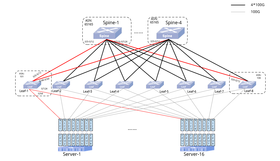
- The ASNs of Leaf1-8 are in increasing order.
- The port numbering rule of each Leaf is the same as that of Leaf1, and the Spine is connected to Leaf in order and the configuration of two Spines is the same; only the interfaces of Leaf1 and Spine1 are labelled in the figure.
- The interface IP configuration is shown in the following table
Table 19 Interface IP Address Table
Leaf1
| Interface | IP Address |
|---|---|
| Ethernet 0/0-0/60 | ipv6 link-local |
| Ethernet 0/64 | 21.10.0.1/24 |
| Ethernet 0/68 | 21.11.0.1/24 |
| Ethernet 0/72 | 21.12.0.1/24 |
| Ethernet 0/76 | 21.13.0.1/24 |
| Ethernet 0/80 | 21.14.0.1/24 |
| Ethernet 0/84 | 21.15.0.1/24 |
| Ethernet 0/88 | 21.16.0.1/24 |
| Ethernet 0/92 | 21.17.0.1/24 |
| Ethernet 0/96 | 21.18.0.1/24 |
| Ethernet 0/100 | 21.19.0.1/24 |
| Ethernet 0/104 | 21.20.0.1/24 |
| Ethernet 0/108 | 21.21.0.1/24 |
| Ethernet 0/112 | 21.22.0.1/24 |
| Ethernet 0/116 | 21.23.0.1/24 |
| Ethernet 0/120 | 21.24.0.1/24 |
| Ethernet 0/124 | 21.25.0.1/24 |
Leaf8
| Device Name | Interface | IP Address |
|---|---|---|
| Leaf-8 | Ethernet 0/0-0/60 | ipv6 link-local |
| Ethernet 0/64 | 28.10.0.1/24 | |
| Ethernet 0/68 | 28.11.0.1/24 | |
| Ethernet 0/72 | 28.12.0.1/24 | |
| Ethernet 0/76 | 28.13.0.1/24 | |
| Ethernet 0/80 | 28.14.0.1/24 | |
| Ethernet 0/84 | 28.15.0.1/24 | |
| Ethernet 0/88 | 28.16.0.1/24 | |
| Ethernet 0/92 | 28.17.0.1/24 | |
| Ethernet 0/96 | 28.18.0.1/24 | |
| Ethernet 0/100 | 28.19.0.1/24 | |
| Ethernet 0/104 | 28.20.0.1/24 | |
| Ethernet 0/108 | 28.21.0.1/24 | |
| Ethernet 0/112 | 28.22.0.1/24 | |
| Ethernet 0/116 | 28.23.0.1/24 | |
| Ethernet 0/120 | 28.24.0.1/24 | |
| Ethernet 0/124 | 28.25.0.1/24 |
- Configuration Roadmap (1) Configure the interface IP, router BGP, intelligent routing mode and router type of the device. (2) Configure intelligent routing uplink (interface list, BGP mode). (3) Configure intelligent routing downlink instance (interface list, routing mode, and ip-list).
- Procedure The following configuration takes Leaf-1 and Spine-1 as examples. Connect each device correctly, and configure the interface IP of each device as required.(omitted)
- Configure Router BGP.
## Spine-1sonic# configure terminalsonic(config)# router bgp 65165sonic(config-router)# no bgp ebgp-requires-policy## Leaf-1sonic# configure terminalsonic(config)# router bgp 101sonic(config-router)# no bgp ebgp-requires-policy- Configure router type of the device.
## Spine-1sonic# configure terminalsonic(config)# router-type spine- Configure intelligent routing mode
sonic# configure terminalsonic(config)# ai-network mode dynamic- Configure Spine downlink
## Spine-1sonic# configure terminalsonic(config)# ai-network downlink-list 0/0-0/124sonic(config)# ai-network downlink bgp-link-local- Configure Leaf uplink
## Leaf-1sonic# configure terminalsonic(config)# ai-network uplink-list 0/0-0/60sonic(config)# ai-network uplink bgp-link-local- Configure intelligent routing downlink instance
sonic# configure terminalsonic(config)# ai-network instance 10sonic(config-ai-network-10)# downlink-list 0/64-0/124sonic(config-ai-network-10)# downlink-mode arp## Configured based on actual user IPssonic(config-ai-network-10-arp)# ip-list 21.10.0.2, 21.11.0.2, 21.12.0.2, 21.13.0.2, 21.14.0.2, 21.15.0.2, 21.16.0.2, 21.17.0.2, 21.18.0.2, 21.19.0.2, 21.20.0.2, 21.21.0.2, 21.22.0.2, 21.23.0.2, 21.24.0.2, 21.25.0.2- Verify the Configuration
- Confirm the router type of the device
sonic# show router-typerouter-type : leaf- Confirm intelligent routing summary configuration
sonic# show ai-network summaryAI NETWORK INFO : ai network mode : dynamicUPLINK : uplink list : 0/0-0/60 use bgp link local : true- Confirm intelligent routing instance configuration
sonic# show ai-network instance allAI NETWORK Instance : 10 downlink list : 0/64-0/124 downlink mode : arp downlink iplist : 21.10.0.2,21.11.0.2,21.12.0.2,21.13.0.2,21.14.0.2,21.15.0.2,21.16.0.2 21.17.0.2,21.18.0.2,21.19.0.2,21.20.0.2,21.21.0.2,21.22.0.2,21.23.0.2,21.24.0.2,21.25.0.2ROUTE TABLE :vrf Prefix Nexthop Ifname Weight Local or Remote----- -------- --------- -------- -------- -----------------NEIGH TABLE :Ifname IP Neigh Mac Family Extern Learn-------- ---- ----------- -------- --------------Server-1 is forwarding traffic between different NICs to each other successfully without packet loss.
The same numbered NICs between server-1 and server-2 are forwarding to each other successfully without packet loss.