
OSPF Configuration Guide
Introduction
Section titled “Introduction”OSPF (Open Shortest Path First) is an internal gateway protocol based on link state developed by the IETF organization, which is used to announce routing information in a single autonomous system. It has the advantages of fast convergence of routing changes, no routing loops, support for variable-length subnet masks (VLSM), and support for area division, etc. After deploying the OSPF protocol in the network, most routes will be automatically calculated and generated, eliminating the need for manual configuration by network administrators. When the network topology changes, the protocol can automatically recalculate and correct routes, significantly facilitating network management. Before the advent of OSPF, RIP (Routing Information Protocol) was widely used as an internal gateway protocol in the network. Since the RIP is a routing protocol based on the distance-vector algorithm, it suffers from issues such as slow convergence, routing loops, and poor scalability. As a result, it has gradually been replaced by the OSPF. Currently, OSPF Version 2 (RFC2328) is used for the IPv4 protocol, while OSPF Version 3 (RFC5340) is used for the IPv6 protocol.
Basic Concepts
Section titled “Basic Concepts”Link State
Section titled “Link State”OSPF is a link-state routing protocol. The link can be thought of as a router’s interface, and the link state can be thought of as a collection of interface and neighbor information, including the interface IP, mask, neighbors, and so on.
In the OSPF, “cost” is used as the routing metric. If the interface cost is not specified, the interface cost is calculated as the OSPF reference bandwidth divided by the interface bandwidth, with the OSPF reference bandwidth being 100 Mbps. If the calculated value is less than 1, the cost is set to 1. The calculation of the route cost is the sum of the costs of all ingress interfaces from the origin of the route to reach the local network.
Router ID
Section titled “Router ID”Router ID is a 32-bit value used to identify an OSPF device, usually in the form of IPv4 address. The Router ID can be manually configured on the router running OSPF, or automatically generated by the router. Typically, when a Router ID is not manually configured, the router will select the largest IP address among its interface addresses to be used as the Router ID.
OSPF is a link-state routing protocol in which all routers broadcast the link state of their connected networks. Each router then uses this comprehensive link-state information to construct its own view of the network topology, upon which route calculations are based. However, when the network size is large, the amount of link state broadcasts will become large, affecting the scalability of OSPF. To resolve this issue, OSPF introduced the concept of Area. In OSPF, there are five types of areas: Standard Area, Stub Area, Totally Stub Area, NSSA (Not-So-Stubby Area), and Totally NSSA.
Table 1 OSPF area type
| Area Type | Description |
|---|---|
| Standard Area | Generally, the OSPF area type is defined as a standard area, which can be categorized into standard areas and backbone areas:- Standard Area: Receives routing information from within the area, between areas, and from outside the autonomous system.- Backbone Area: Serves as the central area connecting other OSPF areas, which uses the special OSPF Area 0 (often written as Area 0.0.0.0) |
| Stub Area | Does not accept routing information from outside the autonomous system. External route information is advertised by the area’s ABR (Area Border Router) as a Type 3 default route into the area. |
| Totally Stub Area | Only receives internal area routing information. External routes and inter-area routing information are advertised into the area by the Area Border Router (ABR) as a Type 3 default route. |
| NSSA (Not-So-Stubby Area) | Permits the introduction of external autonomous system routes while maintaining the characteristics of a STUB area within the autonomous system. |
| Totally NSSA | Permits the introduction of external autonomous system routes while maintaining the characteristics of a Totally Stub area within the autonomous system. |
Classification of OSPF routers
Section titled “Classification of OSPF routers”When the AS is split into OSPF areas, the routers are further divided according to function into the following four overlapping categories.
- Internal routers: A router with all directly connected networks belonging to the same area.
- Area border routers: A router that attaches to multiple areas. Area border routers condense the topological information of their attached areas for distribution to the backbone. The backbone in turn distributes the information to the other areas.
- Backbone routers: A router that has an interface to the backbone area. This includes all routers that interface to more than one area (i.e., area border routers). However, backbone routers do not have to be area border routers. Routers with all interfaces connecting to the backbone area are supported.
- AS boundary routers: A router that exchanges routing information with routers belonging to other Autonomous Systems. Such a router advertises AS external routing information throughout the Autonomous System. AS boundary routers may be internal or area border routers, and may or may not participate in the backbone.
LSA (Link State Advertisement), is used to carry and transmit link state information, including adjacent routing information, directly connected link information, area information, etc. Currently, various LSA types are defined. The table below enumerates the commonly encountered LSA types.
Table 2 LSA Type
| LAS Type | Name | Router | Description |
|---|---|---|---|
| Type-1 | Router LSA | All routers | This LSA describes the link-state and cost of a device and can only be propagated within its originating area. |
| Type-2 | Network LSA | DR | It describes the link-state of routers in a multi-access network and is propagated only within its originating area. |
| Type-3 | Network Summary LSA | ABR | It describes the network prefixes and cost metrics to reach other areas, enabling routers to perform inter-area route calculation. |
| Type-4 | ASBR Summary LSA | ABR | It describes the route to the ASBR and is advertised to other relevant areas except the one where the ASBR resides. |
| Type-5 | AS External LSA | ASBR | It describes routes to external AS and is advertised to all areas except STUB areas and NSSA. |
| Type-7 | NSSA LSA | ASBR | It describes routes to external AS and is propagated only within NSSA. |
The support for different types of LSAs in different OSPF areas is as follows:
Table 3 Support for LSA dissemination in various areas
| Area Type | Type-1 | Type-2 | Type-3 | Type-4 | Type-5 |
|---|---|---|---|---|---|
| Standard Area, | 1 | 1 | 1 | 1 | 1 |
| Stub Area | 1 | 1 | 1 | 0 | 0 |
| Totally Stub Area | 1 | 1 | 0 | 0 | 0 |
| NSSA Area | 1 | 1 | 1 | 0 | 0 |
| Totally NSSA Area | 1 | 1 | 0 | 0 | 0 |
In Totally STUB and Totally NSSA areas, no Type-3 LSAs can be propagated except for the default routes of ABR-generated Type-3 LSAs.
OSPF protocol message
Section titled “OSPF protocol message”Table 4 Message type
| Message type | Description |
|---|---|
| Hello | Hello packets are sent out each functioning router interface. They are used to discover and maintain neighbor relationships |
| DD(Database Description) | After the OSPF neighbor relationship is established, DD packets are used for describing its local LSDB (Link State Database). Upon receiving this information, routers compare it with their own LSDB to synchronize the LSDB within the area. |
| LSR(Link-State Request) | LSR packets are used to request the necessary LSAs from the counterpart |
| LSU(Link-State Update) | LSU packets are used to response to the LSR. |
| LSAck | LSAck are used to send an acknowledgment message in response to receiving an LSU from the peer. |
Neighbor States
Section titled “Neighbor States”In an OSPF network, two routers need to establish an adjacency to exchange routing information. Neighbor relationships and adjacency relationships are distinct.
- Neighbor Relationships: OSPF routers detect each other via Hello packets on a shared subnet. If the information (e.g., Area ID, Hello/Dead intervals) carried in Hello packets matches, two routers will form a neighbor relationship
- Adjacency Relationships: Adjacency is a deeper relationship where routers synchronize their Link-State Databases by exchanging DD, LSR, and LSU packets. There are seven types of neighbor states in OSPF.
Table 5 Neighbor states
| Neighbor states | Description |
|---|---|
| Down | It’s the initial stage of the neighbor session, indicating that no active neighbor has been detected. |
| Init | When the received Hello packet does not contain its own Router ID, the state transitions to Init |
| 2-way | When the received Hello packet contain its own Router ID, the state transitions to 2-Way. At this point, the neighbor relationship has been established and link status data can be shared. |
| Exstart | The state transitions to Exstart when master-slave relationship negotiation begins and the DD sequence number is determined. |
| Exchange | The state transitions to Exchange when master-slave relationship negotiation has finished and the DD message begin to be exchanged. |
| Loading | The state transitions to Loading when DD message exchange has completed. |
| Full | The state transitions to Full when the LSR retransmission list is empty. |
Authentication
Section titled “Authentication”OSPF supports three authentication methods: Interface Authentication, Area Authentication, and Virtual Link Authentication. Each of these methods can use either Plain Text authentication or Message Digest (MD5) authentication. Plain Text authentication transmits credentials in text, which can be intercepted by network sniffers and is therefore insecure. It is not recommended. In contrast, Message Digest (MD5) authentication encrypts credentials before transmission, making it the preferred method for secure deployments.
Table 6 Authentication methods
| Authentication | Description |
|---|---|
| Interface Authentication | Enable authentication for all packets on this interface. |
| Area Authentication | Enable authentication for all packets on all interface in this area. |
| Virtual Link Authentication | Enable authentication for all packets on virtual link. |
Route aggregation refers to the process where an Area Border Router combines routes with common subnet prefixes into a single route and advertises it to other areas. By implementing inter-area route aggregation, the number of routing information is reduced, thereby reducing routing table sizes and improving device performance. OSPF does not support automatic route aggregation; it requires manual configuration. OSPF offers two aggregation mechanisms: inter-area route aggregation and external route aggregation. Inter-area route aggregation, also known as ABR aggregation, refers to the process where an ABR combines routes generated by Type-1 LSAs or Type-2 LSAs within its directly connected area. This reduces the number of Type-3 LSAs propagated to other directly connected areas. External route aggregation, also known as ASBR aggregation, refers to the process where an ASBR combines external routes introduced into the OSPF network. This reduces the number of Type-5 LSAs within the OSPF domain.
Network Types
Section titled “Network Types”In OSPF network, there are four network types based on the link layer protocol type.
- Broadcast: The OSPF network type defaults to Broadcast when the link-layer protocol is Ethernet or FDDI. In such networks, DR and BDR are automatically elected, and manual neighbor configuration is not required.
- Non-Broadcast Multiple Access(NBMA): The OSPF network type defaults to NBMA when the link-layer protocol is Frame Relay or X.25. In such networks, DR is elected, all protocol packets are sent via unicast, and manual neighbor configuration is required.
- Point-to-Multipoint(P2MP): OSPF does not automatically assign the P2MP network type to any link-layer protocol. P2MP must be manually configured by overriding the original network type. In this type, Hello packets are sent via multicast, while other protocol packets (e.g., DD, LSR, LSU) use unicast. P2MP networks do not elect a DR/BDR and do not require manual neighbor configuration.
- Point-to-Point(P2P): The OSPF network type defaults to P2P when the link-layer protocol is PPP, HDLC or LAPB. In such networks, there is no need to elect a DR/BDR. Multicast address 224.0.0.5 is used to send various protocol packets, allowing routers to automatically form full adjacencies without manual neighbor configuration. DR in the above context means Designated Router and BDR means Backup Designated Router. After the election of a DR, all routers send their information only to the DR, which broadcasts the LSA. This mechanism reduces synchronization overhead within the area, lowers router memory consumption, minimizes routing update traffic, and ensures all routers in the same area maintain identical link-state information. The DR is not manually assigned but elected autonomously by routers in the area. The router with the highest priority becomes the DR (the default priority for all OSPF routers is 1, but this can be modified via configuration commands; a priority of 0 excludes a router from the election). If priorities are equal, the router with the highest Router ID is elected as the DR.
OSPF Configuration
Section titled “OSPF Configuration”Prerequisite: Configure the interface IP so that the network layer of adjacent nodes is reachable.
Table 7 Overview of OSPF Configuration Tasks
| Configuration Tasks | Description | Refer to | |
|---|---|---|---|
| Basic functions | Enable OSPF | Required | Enable OSPF |
| Configure OSPF area | Required | Configure OSPF area | |
| Configure cost for interface | Optional | Configure cost for interface | |
| Configure OSPF reference bandwidth | Optional | Configure OSPF reference bandwidth | |
| Configure OSPF network type | Optional | Configure OSPF network type | |
| Configure OSPF interface priority | Optional | Configure OSPF interface priority | |
| Configure OSPF parameters | Optional | Configure OSPF parameters | |
| Configure OSPF interface authentication | Optional | Configure OSPF interface authentication | |
| Configure OSPF area authentication | Optional | Configure OSPF area authentication | |
| Configure OSPF route introduction | Optional | Configure OSPF route introduction | |
| Enable BFD with OSPF Linkage | Optional | Enable OSPF with BFD |
OSPF Default Setting
Section titled “OSPF Default Setting”Table 8 OSPF Default Setting
| Parameter | Default value |
|---|---|
| OSPF | Disable |
| Area type | Standard Area |
| Router ID | Largest address in interface IP address list |
| Network type | Broadcast |
| OSPF parameters | Hello packets interval: 10sLSA retransmission interval: 5sTimeout interval: 40s |
Enable OSPF
Section titled “Enable OSPF”Table 9 Enable OSPF
| Purpose | Commands | Description |
|---|---|---|
| Enter global configuration view. | configure terminal | - |
| Configure OSPF packet trap to CPU | ospf enable | Default disable |
| Configure OSPF instance. | router ospf [vrf vrf-name] | - |
| Configure the Router ID | ospf router-id x.x.x.x | The Router ID uniquely identifies a device within an Autonomous System |
Configure OSPF area
Section titled “Configure OSPF area”Table 10 Configure OSPF Area
| Purpose | Commands | Description |
|---|---|---|
| Enter global configuration view. | configure terminal | - |
| Enter interface configuration view | interface {ethernet interface-name[.subinterface-number] |link-aggregation lag-id[.subinterface-number]|vlan vlan-id} | - |
| Configure area-id | ip ospf area area_id | area_id: range 0-4294967295. |
| Enter OSPF configuration view. | router ospf [vrf vrf_name] | - |
| (Optional)Configure area type | area area_id {stub|nssa} | Area type cannot be configured as a Stub area or NSSA area when area id is 0. By default, an area without explicit type configuration is classified as a standard area. |
Configure cost for interface
Section titled “Configure cost for interface”Table 11 Configure Cost For Interface
| Purpose | Commands | Description |
|---|---|---|
| Enter global configuration view | configure terminal | - |
| Enter interface configuration view | interface {ethernet interface-name[.subinterface-number] |link-aggregation lag-id[.subinterface-number]|vlan vlan-id} | - |
| Configure the cost | ip ospf cost value | value: range 1-65535. |
Configure OSPF reference bandwidth
Section titled “Configure OSPF reference bandwidth”Table 12 Configure Reference Bandwidth
| Purpose | Commands | Description |
|---|---|---|
| Enter global configuration view | configure terminal | - |
| Enter OSPF configuration view. | router ospf [vrf vrf_name] | - |
| Configure reference bandwidth | auto-cost reference-bandwidth bandwidth | bandwidth: range 1- 4294967Mbps. |
Configure OSPF network type
Section titled “Configure OSPF network type”Table 13 Configure OSPF Network Type
| Purpose | Commands | Description |
|---|---|---|
| Enter global configuration view | configure terminal | - |
| Enter interface configuration view | interface {ethernet interface-name[.subinterface-number] |link-aggregation lag-id[.subinterface-number]|vlan vlan-id} | - |
| Configure OSPF network type | ip ospf network {broadcast|non-broadcast|point-to-multipoint|point-to-point} | The default network type is broadcast. |
Configure OSPF interface priority
Section titled “Configure OSPF interface priority”Table 14 Configure OSPF Interface Priority
| Purpose | Commands | Description |
|---|---|---|
| Enter global configuration view | configure terminal | - |
| Enter interface configuration view | interface {ethernet interface-name[.subinterface-number] |link-aggregation lag-id[.subinterface-number]|vlan vlan-id} | - |
| Configure OSPF priority | ip ospf priority priority | priority: range 0-255. |
Configure OSPF parameters
Section titled “Configure OSPF parameters”Table 15 Configure OSPF Parameters
| Purpose | Commands | Description |
|---|---|---|
| Enter global configuration view | configure terminal | - |
| Enter interface configuration view | interface {ethernet interface-name[.subinterface-number] |link-aggregation lag-id[.subinterface-number]|vlan vlan-id} | - |
| Configure Hello packets interval | ip ospf hello-interval seconds | range: 1-65535 |
| Configure timeout interval | ip ospf dead-interval seconds | range: 1-65535 |
| Configure LSA retransmission interval | ip ospf retransmit-interval seconds | range: 1-65535 |
Configure OSPF interface authentication
Section titled “Configure OSPF interface authentication”Table 16 Configure OSPF Interface Authentication
| Purpose | Commands | Description |
|---|---|---|
| Enter global configuration view | configure terminal | - |
| Enter interface configuration view | interface {ethernet interface-name[.subinterface-number] |link-aggregation lag-id[.subinterface-number]|vlan vlan-id} | - |
| Configure Authentication Methods | ip ospf authentication [message-digest] | When the configuration command does not include ‘message-digest’, the authentication method is plain text authentication; when ‘message-digest’ is included, the authentication method is message digest (md5) authentication |
| Configure the key for plain text authentication | ip ospf authentication-key auth-key | auth-key: length should be no more than 8 characters. |
| Configure the key for method is message digest authentication | ip ospf message-digest-key key-id md5 auth-key | key-id: range 1-255. auth-key: length should be no more than 16 characters. |
Configure OSPF area authentication
Section titled “Configure OSPF area authentication”Table 17 Configure OSPF Area Authentication
| Purpose | Commands | Description |
|---|---|---|
| Enter global configuration view | configure terminal | - |
| Enter interface configuration view | interface {ethernet interface-name[.subinterface-number] |link-aggregation lag-id[.subinterface-number]|vlan vlan-id} | - |
| Configure the key for plain text authentication | ip ospf authentication-key auth-key | auth-key: length should be no more than 8 characters. |
| Configure the key for method is message digest authentication | ip ospf message-digest-key key-id md5 auth-key | key-id: range 1-255. auth-key: length should be no more than 16 characters. |
| Exit interface configuration view | exit | - |
| Enter OSPF configuration view. | router ospf [vrf vrf_name] | - |
| Configure Authentication Methods | area area-id authentication [message-digest] | When the configuration command does not include ‘message-digest’, the authentication method is plain text authentication; when ‘message-digest’ is included, the authentication method is message digest (md5) authentication |
Configure OSPF route introduction
Section titled “Configure OSPF route introduction”Table 18 Configure OSPF Route Introduction
| Purpose | Commands | Description |
|---|---|---|
| Enter global configuration view | configure terminal | - |
| Enter OSPF config view. | router ospf [vrf vrf_name] | - |
| Configure route introduction | redistribute {ospf|kernel| connected|static|rip|bgp} | - |
Enable OSPF with BFD
Section titled “Enable OSPF with BFD”Table 19 Enable OSPF with BFD
| Purpose | Commands | Description |
|---|---|---|
| Enter global configuration view | configure terminal | - |
| Enter interface configuration view | interface {ethernet interface-name[.subinterface-number] |link-aggregation lag-id[.subinterface-number]|vlan vlan-id} | - |
| Configure OSPF with BFD. | ip ospf bfd [profile profile-name] | You can modify BFD session parameters via binding to a user-defined BFD profile. The default BFD parameters are set to 3×300ms. |
Display and Maintenance
Section titled “Display and Maintenance”Table 20 OSPF Configuration Display
| Purpose | Commands | Description |
|---|---|---|
| Show OSPF neighbor information | show ip ospf neighbor [OPTIONs] | The options for OPTIONs are as follows:all: Display summary information of all neighbors.json: Display OSPF neighbor information in json format.detail: Display neighbor details.A.B.C.D: Display information about neighbors with the specified Router ID.ethernet: Display neighbor information for the specified physical port.vlan: Display neighbor information for the specified VLANIF.link-aggregation: Display neighbor information for the specified LAG port. |
| Display OSPF neighbor information for the specified interface | show ip ospf interface [OPTIONs] | The options for OPTIONs are as follows:ethernet: Display neighbor information for the specified physical port.vlan: Display neighbor information for the specified VLANIF.link-aggregation: Display neighbor information for the specified LAG port.json: Display OSPF neighbor information in json format.traffic: Display OSPF packet counts. |
| Display OSPF Routing Information | show ip ospf route [OPTIONs] | The options for OPTIONs are as follows:json: Display OSPF routing information in json format. |
| Display OSPF Link-State Information | show ip ospf database | - |
Typical Configuration Example
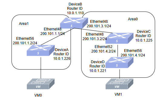
Section titled “Typical Configuration Example”- Networking Requirements Hosts on different network segments are connected via four switches, all running the OSPF protocol. It is required to configure OSPF neighbors so that PC1 hanging under Switch D and PC0 hanging under SwitchA can interoperate.
- Topology
- Configuration Roadmap
- First check that the status of each interface is UP and that the wiring is correct.
- Configure the IP address of each interface and the Loopback0 IP.
- Configure the OSPF Router-ID.
- Configure OSPF Area ID, authentication methods and authentication-key.
- Import direct routes into the OSPF protocol on Switch A and Switch D.
- Procedure
Switch A
interface loopback 0 ip address 10.0.1.226 exit!interface ethernet 0/56 fec rs ip address 200.101.1.2/24 mtu 9216 speed 100000 ip ospf area 1 ip ospf authentication ip ospf authentication-key 12345678 exit!ospf enable!interface ethernet 0/0 fec rs ip address 200.101.2.1/24 mtu 9216 speed 100000 description to_PC0 exit!router ospf ospf router-id 10.0.1.226 redistribute connected exit**Switch B**interface loopback 0 ip address 10.0.1.110 exit!interface ethernet 0/48 fec rs ip address 200.101.1.1/24 mtu 9216 speed 100000 ip ospf area 1 ip ospf authentication ip ospf authentication-key 12345678 exit!interface ethernet 0/56 fec rs ip address 200.101.3.1/24 mtu 9216 speed 100000 ip ospf area 0 ip ospf message-digest-key 1 md5 12345678 exit!ospf enable!router ospf ospf router-id 10.0.1.110 area 0 authentication message-digest exitSwitch C
interface loopback 0 ip address 10.0.1.225 exit!interface ethernet 0/48 fec rs ip address 200.101.3.2/24 mtu 9216 speed 100000 ip ospf area 0 ip ospf message-digest-key 1 md5 12345678exit!interface ethernet 0/52 fec rs ip address 200.101.4.2/24 mtu 9216 speed 100000 ip ospf area 0 ip ospf message-digest-key 1 md5 12345678 exit!ospf enable!router ospf ospf router-id 10.0.1.225 area 0 authentication message-digest exitSwitch D
interface loopback 0 ip address 10.0.1.221 exit!interface ethernet 0/56 fec rs ip address 200.101.4.1/24 mtu 9216 speed 100000 ip ospf area 0 ip ospf message-digest-key 1 md5 12345678 exit!interface ethernet 0/0 fec rs ip address 200.101.5.1/24 mtu 9216 speed 100000 description to_PC1 exit!ospf enable!router ospf ospf router-id 10.0.1.221 redistribute connected area 0 authentication message-digest exit- Verify the configuration
#Check if the OSPF connection is established successfully.
Switch A
sonic# show ip ospf neighborNeighbor ID Pri State Up Time Dead Time Address Interface RXmtL RqstL DBsmL10.0.1.110 1 Full/DR 1h44m56s 33.289s 200.101.1.1 ethernet 0/56:200.101.1.2 0 0 0Switch B
sonic# show ip ospf neighborNeighbor ID Pri State Up Time Dead Time Address Interface RXmtL RqstL DBsmL10.0.1.226 1 Full/Backup 1h47m33s 34.972s 200.101.1.2 ethernet 0/48:200.101.1.1 0 0 010.0.1.225 1 Full/DR 1h27m07s 32.434s 200.101.3.2 ethernet 0/56:200.101.3.1 0 0 0Switch C
sonic# show ip ospf neighborNeighbor ID Pri State Up Time Dead Time Address Interface RXmtL RqstL DBsmL10.0.1.110 1 Full/Backup 1h28m48s 38.460s 200.101.3.1 ethernet 0/48:200.101.3.2 0 0 010.0.1.221 1 Full/Backup 1h25m24s 35.713s 200.101.4.1 ethernet 0/52:200.101.4.2 0 0 0Switch D
sonic# show ip ospf neighborNeighbor ID Pri State Up Time Dead Time Address Interface RXmtL RqstL DBsmL10.0.1.225 1 Full/DR 1h25m58s 37.968s 200.101.4.2 ethernet 0/56:200.101.4.1 0 0 0#Check for successful OSPF route exchange.
Switch A
sonic# show ip route ospfCodes: K - kernel route, C - connected, S - static, R - RIP, O - OSPF, I - IS-IS, B - BGP, E - EIGRP, N - NHRP, T - Table, v - VNC, V - VNC-Direct, A - Babel, F - PBR, f - OpenFabric, > - selected route, \* - FIB route, q - queued, r - rejected, b - backup t - trapped, o - offload failureO>* 10.1.0.1/32 [110/20] via 200.101.1.1, ethernet 0/56, weight 1, 01:16:20O>* 10.1.0.137/32 [110/20] via 200.101.1.1, ethernet 0/56, weight 1, 01:16:20O>* 10.226.148.0/24 [110/20] via 200.101.1.1, ethernet 0/56, weight 1, 01:16:20O>* 10.250.0.0/24 [110/20] via 200.101.1.1, ethernet 0/56, weight 1, 01:16:20O>* 99.0.0.0/24 [110/20] via 200.101.1.1, ethernet 0/56, weight 1, 01:16:20O>* 172.1.1.0/24 [110/20] via 200.101.1.1, ethernet 0/56, weight 1, 01:16:20O>* 172.2.1.0/24 [110/20] via 200.101.1.1, ethernet 0/56, weight 1, 00:38:40O 200.101.1.0/24 [110/10000] is directly connected, ethernet 0/56, weight 1, 01:52:41O>* 200.101.3.0/24 [110/10010] via 200.101.1.1, ethernet 0/56, weight 1, 01:32:06O>* 200.101.4.0/24 [110/20010] via 200.101.1.1, ethernet 0/56, weight 1, 01:30:54O>* 200.101.5.0/24 [110/20] via 200.101.1.1, ethernet 0/56, weight 1, 01:16:20Switch D
sonic# show ip route ospfCodes: K - kernel route, C - connected, S - static, R - RIP, O - OSPF, I - IS-IS, B - BGP, E - EIGRP, N - NHRP, T - Table, v - VNC, V - VNC-Direct, A - Babel, F - PBR, f - OpenFabric, > - selected route, \* - FIB route, q - queued, r - rejected, b - backup t - trapped, o - offload failureO>* 10.250.0.0/16 [110/20] via 200.101.4.2, ethernet 0/56, weight 1, 01:18:21O>* 172.16.1.111/32 [110/20] via 200.101.4.2, ethernet 0/56, weight 1, 01:18:21O>* 172.16.1.226/32 [110/20] via 200.101.4.2, ethernet 0/56, weight 1, 01:18:21O>* 200.101.1.0/24 [110/10020] via 200.101.4.2, ethernet 0/56, weight 1, 01:29:28O>* 200.101.2.0/24 [110/10020] via 200.101.4.2, ethernet 0/56, weight 1, 01:29:28O>* 200.101.3.0/24 [110/10010] via 200.101.4.2, ethernet 0/56, weight 1, 01:29:28O 200.101.4.0/24 [110/10] is directly connected, ethernet 0/56, weight 1, 01:29:33The subnet 200.101.2.0/24 is the directly connected segment of Switch A, and the subnet 200.101.5.0/24 is the directly connected segment of Switch D. This indicates that both Switch A and Switch D get each other’s directly connected routes through OSPF.
#Verify connectivity using the ping command.
PC0 and PC1 can ping each other successfully.