
VLAN Configuration Guide
Introduction
Section titled “Introduction”Ethernet is a data network communication technology based on CSMA/CD (Carrier Sense Multiple Access/Collision Detection) shared communication medium. When the number of hosts is high, it can lead to serious conflicts, broadcast flooding, significant performance degradation and even network unavailability. Although LAN interconnection through switches can solve the problem of serious conflicts, it still cannot isolate broadcast packets and improve the quality of the network. VLAN (Virtual Local Area Network) is a communication technology that logically divides a physical LAN into multiple broadcast domains, allowing direct communication between hosts within a VLAN, but not between VLANs, thus limiting broadcast packets to a single VLAN.
Basic Concepts
Section titled “Basic Concepts”Users between different VLANs cannot interoperate, but Layer 3 interworking between VLANs can be achieved by configuring VLAN interfaces on the switch. VLAN interface is a Layer 3 virtual interface that does not exist as a physical entity on the switch. Each VLAN corresponds to a VLAN interface, and once IP address is configured for the VLAN interface, the IP address can be used as a gateway address for network devices within the VLAN, and IP address-based Layer 3 forwarding is performed for packets that need to cross network segments.
VLAN Tag
Section titled “VLAN Tag”VLAN Tag is a unique identifier for a VLAN, also known as 802.1Q Tag.
Interface Type
Section titled “Interface Type”Whether an interface can be assigned to more than one VLAN is related to the link type and the interface type. Depending on the identification of VLAN frames, interfaces can be divided into three types: Access, Trunk and Hybrid.
Table 1 Access, Trunk and Hybrid
| Interface type | Connecting device | Number of VLANs that can be specified |
|---|---|---|
| Access | Hosts | 1 |
| Trunk | Switches or routers | 1-4094 |
| Hybrid | Hosts, switches, routers | Access Link: 1Trunk Link: 1-4094 |
Classification
Section titled “Classification”We use the simplest and most intuitive way to divide VLANs - based on interfaces. This way, VLAN members are defined according to the interfaces of the switches. After the specified interface is added to the specified VLAN, the interface can forward packets from that VLAN, thus enabling hosts within the VLAN to interoperate directly (i.e. Layer 2 interworking), while hosts between VLANs cannot interoperate directly, limiting broadcast packets to one VLAN.
VID and PVID
Section titled “VID and PVID”VID refers to the VLAN ID. e.g. if you add a Vlan100, then the member ports that are classified to that VLAN all have a VID of 100 and they can receive packets with tag100. PVID refers to Port-base VLAN ID, which is an interface-based VLAN ID. An interface can join multiple VLANs, but can only have one PVID. When an interface receives a packet without a Tag, it is tagged with the VLAN Tag of the PVID and processed as packets for that VLAN. A physical port can only have one PVID, and when a physical port has a PVID, it must have a VID equal to the PVID, and on that VID, the physical port must be Untagged Port. e.g., if a port is added to VLAN100 in untagged mode and to VLAN200, the PVID of the port will be 100.
Rules for Sending and Receiving Packets
Section titled “Rules for Sending and Receiving Packets”For different interface types, the switch handles the packets differently, as shown in the table below.
Table 2 Rules for Sending and Receiving Packets
| Interface type | Direction of entry | Outward direction | |
|---|---|---|---|
| untag packet | tag packet | ||
| Access | Allow access and tagging | If the VLAN Tag of the packet is the same as the PVID of the port, it is received and processed. | Remove tag forwarding |
| Trunk | If the VLAN Tag of the packet corresponds to the port allow packet tag, it is received and processed, otherwise it is discarded. | When the VLAN Tag of the packet is the same as the PVID of the port, it is de-tagged and forwarded, otherwise it is tagged. | |
| Hybrid | When the vlan id of the packet is configured as tag on the port, it is tagged and forwarded, otherwise it is de-tagged. |
VLAN Configuration
Section titled “VLAN Configuration”VLAN Default Setting
Section titled “VLAN Default Setting”The default setting of VLAN interface is shown in the table below.
Table 3 VLAN Default Setting
| Parameters | Default value |
|---|---|
| MAC learning for VLAN interfaces | Enable |
| MTU of the VLAN interface | 9216 bytes |
| Broadcast packet handling policy for VLAN interfaces | flood |
Configure VLAN
Section titled “Configure VLAN”Table 4 Configure VLAN
| Purpose | Commands | Description |
|---|---|---|
| Enter global configuration view | configure terminal | - |
| Create VLAN | vlan vlan-id | - |
| Batch creation of VLANs | vlan range vlan-id | Batch create continuous VLANs, connect the starting VLAN ID and ending VLAN ID with ”-”, batch create discontinuous VLANs, separate them with ”,” |
Configure VLAN Member Port
Section titled “Configure VLAN Member Port”Table 5 Configure VLAN Member Port
| Purpose | Commands | Description |
|---|---|---|
| Enter global configuration view | configure terminal | - |
| Enter Ethernet interface view | interface ethernet interface-name | - |
| Switch to Layer 2 interface | switchport | If the interface is in Layer 3 interface mode, please switch to Layer 2 interface mode first. |
| Add member ports | switchport {trunk|access} vlan vlan-id | - |
| Batch add member ports | switchport trunk range vlan vlan-id | - |
Configure the IP of VLAN
Section titled “Configure the IP of VLAN”Table 6 Configure the IP of VLAN
| Purpose | Commands | Description |
|---|---|---|
| Enter global configuration view | configure terminal | - |
| Enter VLANIF configuration view | interface vlan vlan-id | - |
| Configure IP address for the VLAN interface | ip address {A.B.C.D/M|A::B/M} | IPv4 address with subnet mask /32 is not allowed to be configured. Addresses with subnet mask /31 is allowed. In other subnet masks, addresses with the host portion all-zeros or all-ones are not allowed.IPv6 address with subnet mask /127 or /128 is not allowed to be configured. In other subnet masks, addresses with the host portion all-zeros are not allowed, but all-ones are allowed. |
Configure the MTU of VLAN
Section titled “Configure the MTU of VLAN”Table 7 Configure the MTU of VLAN
| Purpose | Commands | Description |
|---|---|---|
| Enter global configuration view | configure terminal | - |
| Enter VLANIF configuration view | interface vlan vlan-id | - |
| Configure the MTU of VLAN interface | mtu mtu | - |
Configure the MAC Address of VLAN
Section titled “Configure the MAC Address of VLAN”By default, the MAC address of the interface is dynamically assigned by the system or is the same as the MAC address of the switch. This series supports users to reconfigure the MAC of physical interfaces, VLAN interfaces and link aggregation interfaces.
Table 8 Configure the MAC Address of VLAN
| Purpose | Commands | Description |
|---|---|---|
| Enter global configuration view | configure terminal | - |
| Enter VLAN interface view | interface vlan vlan-id | - |
| Configure the MAC address of VLANIF | mac-address HH:HH:HH:HH:HH:HH | MAC addresses are not case-sensitive |
Shutdown VLAN
Section titled “Shutdown VLAN”Table 9 Shutdown VLAN
| Purpose | Commands | Description |
|---|---|---|
| Enter global configuration view | configure terminal | - |
| Enter VLANIF configuration view | interface vlan vlan-id | - |
| Shutdown VLANIF | shutdown | - |
Disable MAC Learning for VLAN
Section titled “Disable MAC Learning for VLAN”Table 10 Disable MAC Learning for VLAN
| Purpose | Commands | Description |
|---|---|---|
| Enter global configuration view | configure terminal | - |
| Enter VLAN configuration view | vlan vlan-id | - |
| Disable MAC learning for VLAN interface | no mac-address learning | - |
Display and Maintenance
Section titled “Display and Maintenance”Table 11 VLAN Display and Maintenance
| Purpose | Commands | Description |
|---|---|---|
| Display VLAN summary information | show vlan summary | - |
| Display specific VLAN information | show vlan vlan-id | - |
| Display all VLAN information | show vlan all | - |
| Display VLAN interface count | show counters vlan | - |
Typical Configuration Example
Section titled “Typical Configuration Example”Communication Between VLANs of the Same Device
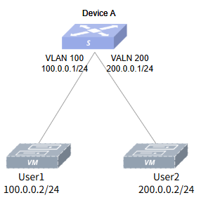
Section titled “Communication Between VLANs of the Same Device”- Networking Requirements Assume that User 1 and User 2 belong to the same department in a company, but belong to different VLANs and are located in different network segments. The requirement is to implement User 1 and User 2 interoperability.
- Topology
- Procedure
#Create VLAN
sonic# configure terminalsonic(config)# vlan 100sonic(config-vlan-100)# exsonic(config)# vlan 200sonic(config-vlan-200)# ex#Add interfaces to VLANs
sonic(config)# interface ethernet 0/0sonic(config-if-0/0)# switchport trunk vlan 100sonic(config-if-0/0)# exsonic(config)# interface ethernet 0/1sonic(config-if-0/1)# switchport trunk vlan 200sonic(config-if-0/1)# ex#Set the IP for VLAN interfaces
sonic(config)# interface vlan 100sonic(config-vlanif-100)# ip address 100.0.0.1/24sonic(config-vlanif-100)# exsonic(config)# interface vlan 200sonic(config-vlanif-200)# ip address 200.0.0.1/24sonic(config-vlanif-200)# ex- Verify configuration
sonic# show vlan summary+-----------+--------------+-----------+----------------+-----------------------+| VLAN ID | IP Address | Ports | Port Tagging | DHCP Helper Address |+===========+==============+===========+================+=======================+| 100 | 100.0.0.1/24 | Ethernet0 | untagged | |+-----------+--------------+-----------+----------------+-----------------------+| 200 | 200.0.0.1/24 | Ethernet1 | untagged | |+-----------+--------------+-----------+----------------+-----------------------+User 1 and User 2 can ping each other.
VLANs Communication Across Devices
Section titled “VLANs Communication Across Devices”- Networking Requirements
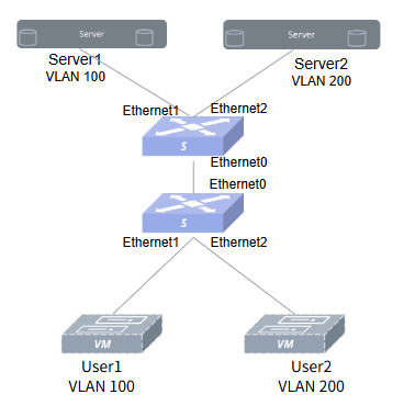
Suppose a company network has Device A connected to servers Server1 and Server2, belonging to Department 1 and Department 2 respectively, and Device B connected to users User 1 and User 2, belonging to Department 1 and Department 2 respectively. To ensure network communication security, the company requires that employees in each department can only access the servers in their own department. According to the communication principle of VLAN: same VLANs can interoperate directly, Layer 2 isolated Layer 3 interoperability between different VLANs. Therefore, User1 and Server1 are divided into the same VLAN, and User2 and Server2 are divided into the same VLAN to realize that the employees of this department can only access the servers of this department.
- Topology
- Procedure
Configure Device A.
#Create VLAN
sonic# configure terminalsonic(config)# vlan 100sonic(config-vlan-100)# exsonic(config)# vlan 200sonic(config-vlan-200)# ex#Add interfaces to VLANs
sonic# configure terminalsonic(config)# interface ethernet 0/1sonic(config-if-0/1)# switchport access vlan 100sonic(config-if-0/1)# exsonic(config)# interface ethernet 0/2sonic(config-if-0/2)# switchport access vlan 200sonic(config-if-0/2)# exConfigure Device B: as above, without further ado. Configure the IP: set User1 and Server1 to the same network segment, e.g. 192.168.100.0/24, and set User2 and Server2 to the same network segment, e.g. 192.168.200.0/24.
- Verify configuration
#Check VLAN configuration.
sonic# show vlan summary+-----------+-----------------+-----------------+----------------+-------------+---------------+-----------------------+|   VLAN ID | IP Address      | Ports           | Port Tagging   | Proxy ARP   | Description   | DHCP Helper Address   |+-----------+-----------------+-----------------+----------------+-------------+---------------+-----------------------+|       100 |                 | 0/0             | tagged         | disable     | N/A           |                       ||           |                 | 0/1             | tagged         |             |               |                       |+-----------+-----------------+-----------------+----------------+-------------+---------------+-----------------------+
|       200 |                 | 0/0             | tagged         | disable     | N/A           |                       ||           |                 | 0/2             | tagged         |             |               |                       |+-----------+-----------------+-----------------+----------------+-------------+---------------+-----------------------+
#On User1, ping Server1 is OK, ping Server2 is not OK.
admin@user1:-$ ping 192.168.100.1PING 192.168.100.1 (192.168.100.1) 56(84) bytes of data.64 bytes from 192.168.100.1: icmp_seq=1 ttl=64 time=2.49 ms64 bytes from 192.168.100.1: icmp_seq=2 ttl=64 time=0.464 ms64 bytes from 192.168.100.1: icmp_seq=3 ttl=64 time=0.518 ms64 bytes from 192.168.100.1: icmp_seq=4 ttl=64 time=0.531 ms64 bytes from 192.168.100.1: icmp_seq=5 ttl=64 time=0.413 ms64 bytes from 192.168.100.1: icmp_seq=6 ttl=64 time=3.82 ms^C--- 192.168.100.1 ping statistics ---6 packets transmitted, 6 received, 0% packet loss, time 5110msrtt min/avg/max/mdev = 0.413/1.371/3.819/1.317 msadmin@user1:-$ ping 192.168.200.1PING 192.168.200.1 (192.168.200.1) 56(84) bytes of data.^C--- 192.168.200.1 ping statistics ---4 packets transmitted, 0 received, 100% packet loss, time 3065ms#on User2, ping Server1 is not OK, ping Server2 is OK.
admin@user2:-$ ping 192.168.200.1PING 192.168.200.1 (192.168.200.1) 56(84) bytes of data.64 bytes from 192.168.200.1: icmp_seq=1 ttl=64 time=2.61 ms64 bytes from 192.168.200.1: icmp_seq=2 ttl=64 time=1.29 ms64 bytes from 192.168.200.1: icmp_seq=3 ttl=64 time=4.33 ms^C--- 192.168.200.1 ping statistics ---3 packets transmitted, 3 received, 0% packet loss, time 2002msrtt min/avg/max/mdev = 1.286/2.742/4.334/1.248 msadmin@user2:-$ ping 192.168.100.1PING 192.168.100.1 (192.168.100.1) 56(84) bytes of data.^C--- 192.168.100.1 ping statistics ---4 packets transmitted, 0 received, 100% packet loss, time 3065ms