
Network Monitoring Configuration Guide
Introduction
Section titled “Introduction”Mirror is a network management technology commonly used for network detection, traffic analysis, and troubleshooting. With the mirroring function, traffic at one or more ports on a switch can be copied to the destination port of the mirror and sent out for analysis and monitoring of the traffic on the mirrored port.
Basic Concepts
Section titled “Basic Concepts”The switch currently supports two mirroring methods: SPAN and ERSPAN.
SPAN
SPAN refers to a mirroring configuration where the source and destination ports are on the same switch. In this configuration, the switch copies the data traffic from the specified source port (mirror source) to another port (destination port) on the same switch and forwards it. The source and destination ports of this mirror are both on the same switch, making the configuration relatively simple and not involving device network connections. Support mirroring traffic from one or more source ports to the destination port.
ERSPAN
ERSPAN refers to a mirroring configuration where the source and destination ports are located on different switches. In this configuration, the switch replicates the data traffic from the specified source port to the destination port on the remote switch through a layer three protocol. This type of image needs to be forwarded through an IP address, and the configuration is relatively complex. Remote mirroring needs to be used in conjunction with ACL policies. Mirror v4 ACL match field support is as follows:
Table 1 Mirror v4 ACL match fields
| Fields | Description |
|---|---|
| outer-vlan outer-vlan | range [1,4094] |
| source-port sport | range 0-65535 |
| destination-port dport | range 0-65535 |
| tcp-flags tcp-flags | range 0-63 |
| source-ip sip | A.B.C.D(/M) |
| destination-ip dip | A.B.C.D(/M) |
| icmp-type icmp-type | range 0-16 |
| icmp-code icmp-code | range 0-5 |
| dscp dscp | range 0-63 |
| ip-type ip-type | any/ip/non_ip/ipv4any/non_ipv4/ipv6any/non_ipv6/arp/arp_request/arp_reply |
| bth-opcode bth-opcode | range 0-255 |
| aeth-syndrome aeth-syndrome | range 0-255 |
| outer-vlan outer-vlan | range [1,4094] |
Mirror v6 ACL match field support is as follows:
Table 2 Mirror v6 ACL match fields
| Fields | Description |
|---|---|
| source-ipv6 sipv6 | X:X::X:X(/M) |
| destination-ipv6 dipv6 | X:X::X:X(/M) |
| bth-opcode bth-opcode | range 0-255 |
| aeth-syndrome aeth-syndrome | range 0-255 |
SPAN Configuration
Section titled “SPAN Configuration”When configuring span, it supports configuring one or more source ports for simultaneous mirroring, but supports configuring one destination port.
Table 3 Configure SPAN
| Purpose | Commands | Description |
|---|---|---|
| Enter global configuration view | configure terminal | - |
| Create span | mirror session session-id type span | The range of session id is from 1 to 63. |
| Configure the span source port | source interface ethernet interface-name | - |
| Configure the span destination port | destination interface ethernet interface-name | - |
| Configure mirror direction | direction {in|out|both} | The default is both, which means that both the inlet and outlet traffic are mirrored |
| commit | commit | After the configuration is completed, commit needs to be executed to take effect. |
ERSPAN Configuration
Section titled “ERSPAN Configuration”Table 4 Configure ERSPAN
| Purpose | Commands | Description |
|---|---|---|
| Enter global configuration view | configure terminal | - |
| Create erspan | mirror session session-id type erspan | The range of session id is from 1 to 63. |
| Configure erspan source IP | origin ip address A.B.C.D | - |
| Configure erspan destination IP | destination ip address A.B.C.D | - |
| Configure TTL value for erspan tunnel | ip ttl ttl_value | The range of TTL value is 1-255. |
| Configure DSCP value for erspan tunnel | ip dscp dscp_value | DSCP value range is 0-63. |
| (Optional)Configure the queue bound to the erspan tunnel | queue queue_value | Queue ID, with a value range of 0-7 |
| (Optional)Configure erspan tunnel type | gre_type type | GRE type, format 0xHHHH |
| commit | commit | After the configuration is completed, commit needs to be executed to take effect |
| Exit mirror configuration view | exit | - |
| Create mirror ACL table and enter configuration view | access-list table_name mirror ingress | - |
| Bind interface | bind interface {{ ethernet|link-aggregation} interface-name | all}} | - |
| Configure mirror rules | rule rule_id rule action mirror-session session-id | rule is the match fields, and the supported fields are detailed in |
Display and Maintenance
Section titled “Display and Maintenance”Table 5 Display and Maintenance
| Purpose | Commands | Description |
|---|---|---|
| show mirror configuration | show mirror | - |
Typical Configuration Example
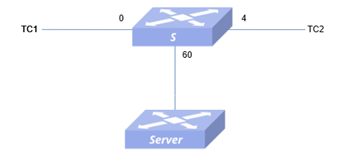
Section titled “Typical Configuration Example”- Network Requirements A certain PC1, with an IP of 10.0.0.2, passes through a switch and achieves mutual access with PC2, with an IP of 20.0.0.2. Now it is necessary to monitor the traffic sent by PC1 to PC2 on the server, and obtain the traffic sent by PC1 without affecting the business
- Topology
- Procedure
#Configure interface IP address
sonic(config)# interface ethernet 0/60sonic(config-if-0/60)# ip address 60.0.0.1/24#Configure erspan
sonic# configuresonic(config)# mirror session 1 type erspansonic(config-erspan-mirror-1)# origin ip address 60.0.0.1Please enter 'commit' to make mirror session command take effectsonic(config-erspan-mirror-1)# destination ip address 60.0.0.2Please enter 'commit' to make mirror session command take effectsonic(config-erspan-mirror-1)# ip ttl 40Please enter 'commit' to make mirror session command take effectsonic(config-erspan-mirror-1)# ip dscp 24Please enter 'commit' to make mirror session command take effectsonic(config-erspan-mirror-1)# commit#Configure ACL policy
sonic# configuresonic(config)# access-list test1 mirror ingresssonic(config-mirror-acl-test1)# bind interface ethernet 0/0sonic(config-mirror-acl-test1)# rule 1 source-ip 10.0.0.2 action mirror-session 1Server
sonic# configuresonic(config)# interface ethernet 0/24sonic(config-if-0/24)# ip address 60.0.0.2- Configuration verification
sonic# show mirrorERSPAN Sessions Name Status SRC IP DST IP GRE DSCP TTL Queue Policer Monitor Port SRC Port Direction------ -------- -------- -------- ----- ------ ----- ------- --------- -------------- ---------- ----------- 1 active 60.0.0.1 60.0.0.2 24 40 0/60SPAN SessionsName Status DST Port SRC Port Direction Queue Policer------ -------- ---------- ---------- ----------- ------- ---------sonic# show acl ruleTable Rule Priority Action Match------- ------ ---------- ----------------- ----------------test1 rule_1 1001 MIRROR INGRESS: 1 SRC_IP: 10.0.0.2- Traffic verification PC1 streams to PC2 and receives mirrored traffic on the server, which is the traffic sent by PC1.
Introduction
Section titled “Introduction”sFlow (Sampled Flow) is a network traffic monitoring technology based on packet sampling, mainly used for statistical analysis of network traffic.
Basic Concepts
Section titled “Basic Concepts”sFlow System
The sFlow system consists of several sFlow Agents (embedded in forwarding device such as switch or router) and a core sFlow Collector, as shown in figure below. sFlow Agents use specific sampling techniques to obtain statistics and packet information about the interface. The sFlow packets are encapsulated in UDP packets and sent to the designated sFlow Collector for analysis by the Collector when the buffer holding the sFlow packets is full or when the sFlow packet delivery timer (timer interval is fixed at 1 second) times out, helping network administrators to manage the network traffic of entire site (usually an enterprise site) more effectively by generating flow views or reports to display the results.

sFlow Sample
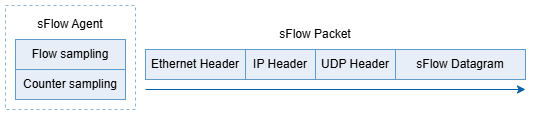
sFlow Agent provides two sampling methods for users to analyze network traffic conditions from different perspectives, namely Flow sampling and Counter sampling.
- Flow sample is used by the sFlow Agent device to sample and analyze packets on a specified interface according to a specific sampling direction and sampling ratio, and is used to obtain information about the data content of the packets. This sampling method focuses on the details of the flow so that it can monitor and analyze popular behavior on the network.
- Counter sampling is the sFlow Agent device that periodically obtains traffic statistics on interfaces. In contrast to Flow sampling, Counter sampling focuses only on the number of flows on interfaces and not on the details of the flows.
Default sFlow Configuration
Section titled “Default sFlow Configuration”The default configuration of sFlow is shown in the table below.
Table 6 sFlow Default Configuration
| Parameters | Default value |
|---|---|
| sFlow Agent information | The Agent automatically selects the IP of the routing out interface to the Collector as the source IP address. |
| sFlow Collector information | Not configured. |
| sFlow sampling rate | 10000 |
sFlow Configuration
Section titled “sFlow Configuration”Table 7 Overview of sFlow Configuration Tasks
| Configuration Tasks | Description |
|---|---|
| Enable sFlow | Optional |
| Configure the sFlow Collector | Optional |
| Configure sFlow for Interface | Optional |
Enable sFlow
Section titled “Enable sFlow”Table 8 Enable sFlow
| Purpose | Commands | Description |
|---|---|---|
| Enter global configuration view | configure terminal | - |
| Enable sFlow | sflow enable | - |
Configure the sFlow Collector
Section titled “Configure the sFlow Collector”- sFlow needs to be enabled before configuration
- The source interface and source IP of sFlow Collector cannot be configured at the same time.
Table 9 Configure the sFlow Collector
| Purpose | Commands | Description |
|---|---|---|
| Enter global configuration view | configure terminal | - |
| Configure the sFlow Collector | sflow collector collector-name ip-address [VRF vrf |dst_port] | ip-address: collector’s destination IPvrf: specifies the VRF where the sampling interface is locateddst_port: collector’s destination port. |
| Configure source IP of sFlow Collector | sflow collector collector-name source {A.B.C.D|A::B} | - |
| Configure source interface of sFlow Collector | sflow collector collector-name source-interface interface-type interface_name | interface-type: optional parameters: vlan, ethernet, loopback, link-aggregation, mgmt. |
| Configure the polling interval | sflow polling-interval time | Sets the counter sample interval for sampling.time: unit s, range 6-3600. |
| Set sFlow sampling rate | sflow sample-rate rate | rate: indicates how many packets are sampled once, range 8000-1000000, and the default value is 10000. |
Configure sFlow for Interface
Section titled “Configure sFlow for Interface”Table 10 Interface sFlow Configuration
| Purpose | Commands | Description |
|---|---|---|
| Enter global configuration view | configure terminal | - |
| Enter Ethernet interface view | interface ethernet interface-name | - |
| Disable sFlow for interface | sflow disable | - |
| Set sFlow sampling rate | sflow sample-rate rate | rate: indicates how many packets are sampled once, range 8000-1000000, and the default value is 10000. |
Display and Maintenance
Section titled “Display and Maintenance”Table 11 sFlow Display and Maintenance
| Purpose | Commands | Description |
|---|---|---|
| Show global configuration | show sflow | - |
| Display interface configuration | show sflow interface ethernet interface-num | - |
Typical Configuration Example
Section titled “Typical Configuration Example”Configure the sFlow Collector
Section titled “Configure the sFlow Collector”- Network Requirements TC1 and TC2 communicate via Switch. Management and maintenance personnel require viewing traffic information, forwarding status on Interface 0/0, and the overall operational status of the device. This enables timely detection of abnormal traffic, thereby ensuring normal and stable network operation.
- Topology

- Procedure
#Configure the interface IP
DUT
sonic# config terminalsonic(config)# interface ethernet 0/0sonic(config-if-0/0)# ip address 10.0.0.2/24Server
sonic# config terminalsonic(config)# interface ethernet 0/0sonic(config-if-0/0)# ip address 10.0.0.3/24#Configure sFlow Collector on Switch
sonic# config terminalsonic(config)# sflow enablesonic(config)# sflow collector 1 10.0.0.3 6345#Configure the polling interval (optional)
sonic# config terminalsonic(config)# sflow polling-interval 30#Configure the sampling rate (optional)
sonic# config terminalsonic(config)# interface ethernet 0/0sonic(config-if-0/0)# sflow sample-rate 80000- Verify the configuration.
#Configuration verification.
sonic(config)# show sflowsFlow Global Information: sFlow Admin State: up sFlow Polling Interval: default sFlow AgentID: default 1 Collectors configured: Name: 1 IP addr: 10.0.0.3 UDP port: 6345sonic# show sflow interface ethernet 0/0+-------------+---------------+-----------------+| Interface | Admin State | Sampling Rate |+=============+===============+=================+| 0/0 | up | 80000 |+-------------+---------------+-----------------+#Flow verification.
TC1 streams to TC2 at wire speed, capturing packets on the corresponding interface of Server. Server can receive sflow packets with destination port 6345.