
MC-LAG Configuration Guide
Introduction
Section titled “Introduction”MC-LAG (Multi Chassis Link Aggregation Group) is a mechanism for implementing cross-device link aggregation by aggregating one device with two other devices across the switch, retaining all the benefits of normal link aggregation while providing device-level redundancy. MC-LAG provides a horizontal virtualization technique that virtualizes two physical devices into a single logical device, and this virtualized “single device” is “one-to-one” with its connected uplink or downlink device for link aggregation.
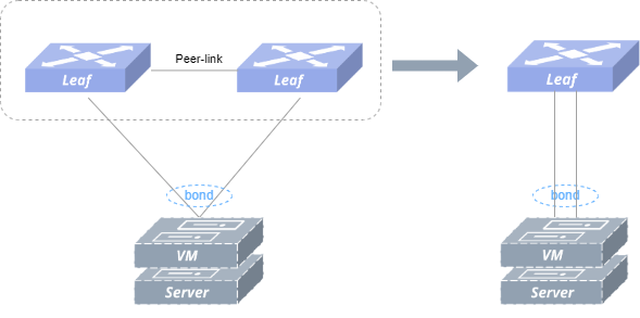
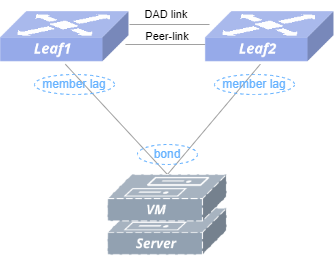
As shown in figure above, the MC-LAG group is externally represented as a logical device for link aggregation; the MC-LAG switch group deploys Ethernet or LAG type peer-link for protocol information interaction between MC-LAG, as well as taking up the east-west traffic in case of failure scenarios. The MC-LAG group is externally presented as a single node, which does not pose a loop risk when implementing redundant backups, and the load balancing mode of link aggregation does not result in idle links, making link utilization more efficient. As shown in figure below, the Server side performs cross-device link aggregation with the other two devices Leaf1 and Leaf2 via the MC-LAG mechanism.
Basic Concepts
Section titled “Basic Concepts”MC-LAG Peer
Section titled “MC-LAG Peer”Refers to the two devices participating in the cross-device link aggregation group. The two MC-LAG peer devices assume the Active and Standby roles respectively. According to the comparison of the size of the local_ip and peer_ip numbers in the configuration information, the smaller number will be the Active side, the Client side of the TCP connection; the larger number will be the Standby side, the Server side of the TCP connection, and the Client side will initiate a connection request to the server.
MC-LAG Member Interface
Section titled “MC-LAG Member Interface”Refers to a series of LAGs that participate in cross-device link aggregation.
Keep-alive link
Section titled “Keep-alive link”The keep-alive link is a heartbeat detection link, typically implemented as a direct Layer 3 connection between MC-LAG peer, periodically sends heartbeat packet. It’s used for transmitting ICCP control protocol packets, synchronizing table information, establishing MC-LAG peer relationships, and implementing configuration consistency checks.
Peer-Link
Section titled “Peer-Link”The peer-link refers to a direct physical link between MC-LAG peers, used to forward traffic when there is a failure in downstream links. Generally, it is recommended to be shared with keep-alive link for operational efficiency and resource optimization.
DAD link
Section titled “DAD link”The DAD (Dual Active Detection) link is a layer 3 interoperable link used by MC-LAG peer to send dual-active detection packets, applicable in scenarios when the peer-link and keep-alive link are shared. When the keep-alive link is detected as disconnected, the system will automatically shut down all interfaces on the standby node except logical interfaces, management ports, and peer-link interfaces.
Working Principle
Section titled “Working Principle”Control Protocols
Section titled “Control Protocols”SONiC uses a lightweight ICCP protocol on the MC-LAG control plane, with only a small amount of consistency checking and packet synchronization while safeguarding functionality. ICCP (Inter-Chassis Communication Protocol), a standard protocol defined in RFC 7275, uses TCP port 8888 to establish a connection between MC-LAG peers, and the lightweight ICCP protocol performs configuration consistency checks, ARP table entry and MAC table entry synchronization.
Neighbor Establishment
Section titled “Neighbor Establishment”The two MC-LAG peer devices establish ICCP neighbor with local_ip and peer_ip as the source and destination addresses of the TCP connection. When the ICCP connection is established, the MC-LAG peer modifies the APP_PORT_TABLE or APP_LAG_TABLE or APP_VXLAN_TUNNEL_TABLE table entry in APP_DB and disables the mac learning function of the peer-link, depending on the port type of the peer-link.
Information Synchronization
Section titled “Information Synchronization”The following information is synchronized between MC-LAG peers.
- System Information Synchronize the MAC addresses of MC-LAG member ports to ensure that the “system ID” field in the LACP packets sent from MC-LAG peer to Server is the same, so as to achieve cross-device link aggregation. To achieve cross-device link aggregation, when the Standby side receives the system MAC information of the Active side, it sends a netlink packet to modify the system ID of the local MC-LAG member port to be the same as that of the Active side.
- MC-LAG member port configuration information Records information such as the name of the local and peer MC-LAG member ports, which is used for consistency checking.
- MC-LAG member port status information The local and peer-LAG member port status is recorded to ensure the isolation of peer-link to MC-LAG member port in case of no fault, and the isolation of peer-link to port of the same name in case of peer-LAG member port fault is released. Isolation is adding table entries to APP_DB, and the table entry is deleted for isolation release.
- ARP information The ARP table entries associated with MC-LAG member ports are synchronized between MC-LAG peers. When an ARP packet is received from the peer, the ARP table entry is updated locally by sending a netlink packet.
- FDB Information The FDB table entries associated with MC-LAG member ports are synchronized between MC-LAG peers. Upon receipt of FDB packets from the peer, the local FDB table entries are updated by modifying the table entries in APP_DB.
Heartbeat Detection
Section titled “Heartbeat Detection”In SONiC, a heartbeat packet is sent to the other end at 1s intervals. If a heartbeat packet is not received for 15 consecutive cycles, it is judged to have timed out and the ICCP connection is broken.
Consistency Check
Section titled “Consistency Check”SONiC uses the lightweight ICCP protocol for consistency checking of the following attributes: symmetrical configuration of MC-LAG peer in local_ip, peer_ip; same configuration of MC-LAG member ports: name, number, joined VLAN, routing port IP of VLAN, routing port MAC address of VLAN; same configuration of MC-LAG peer in the port type of peer-link. The MC-LAG solution provides an automatic detection mechanism that supports the following three modes:
- Idle Mode In this mode, consistency checks only display the relevant results without performing any processing.
- Default Mode In this mode, member ports failing detection will be shut down on two peers.
- Graceful Mode In this mode, member ports failing detection will be shut down on standby node. The default mode for MC-LAG consistency checks is the idle mode.
MC-LAG Configuration
Section titled “MC-LAG Configuration”Table 1 Overview of MC-LAG Configuration Tasks
| Configuration Tasks | Description | Refer to | |
|---|---|---|---|
| MC-LAG Configuration | Configure MC-LAG | Required | Configure MC-LAG |
| Configure Peer-link | Required | Configure Peer-link | |
| Configure Keep-alive | Required | Configure Keep-alive | |
| Configure MC-LAG Member | Required | Configure MC-LAG Member | |
| Configure Monitor Link Group | Required | Configure Monitor Link Group | |
| Configure Dual-Active Gateway | Optional | Configure Dual-Active Gateway | |
| Configure DAD-link | Optional | Configure DAD-link | |
| Configure Consistency Check Mode | Optional | Configure Consistency Check Mode | |
| Configure MSTP | Optional | Configure MSTP | |
| Configure ICCP Backup Channel | Optional | Configure ICCP Backup Channel | |
| Configure Loopback-Detect | Optional | Configure Loopback-Detect | |
| Configure Unique IP | Optional | Configure Unique IP |
MC-LAG Default Setting
The default setting of the MC-LAG is shown in the table below.
Table 2 MC-LAG Default Setting
| Parameters | Default value |
|---|---|
| heartbeat-interval | 1s |
| session timeout | 15s |
| consistency-check mode | idle |
| MCLAG VRF | default |
| DAD detection delay | 60s |
| DAD recovery delay (MCLAG member) | 60s |
| DAD recovery delay (not MCLAG member) | 0s |
| DAD VRF | default |
Configure MC-LAG
Section titled “Configure MC-LAG”Table 3 MC-LAG Basic Configuration
| Purpose | Commands | Description |
|---|---|---|
| Enter global configuration view | configure terminal | - |
| Create MC-LAG domain | mclag domain domain-id | Only one domain is currently supported, with range of 1-4095 |
| (Optional) Configure the MC-LAG session timeout | session-timeout timeout | Timeout time, in seconds, value range is 3-3600, default value is 15 seconds; the time interval of the heartbeat detection message should be less than 1/3 of the MC-LAG session timeout time; the session timeout time should be a multiple of the time interval of the heartbeat detection message |
Configure Peer-link
Section titled “Configure Peer-link”- Peer-link is recommended to use a high-speed interface for interconnection, and it is recommended that a directly connected aggregation link located between two MC-LAG devices be used as a Peer-link link, and it is recommended that it be configured as a static aggregation in order to improve the reliability of MC-LAGs
- After interface is configured as a peer-link interface, no other services can be configured on this interface
- Assign a dedicated VLAN for the peer-link and add the peer-link to other MC-LAG service VLANs
- Configure interface delayed startup on the physical port where the peer-link is located so that it is up before the up/downlink port up, so that the MC-LAG state is restored and the table entries are synchronized and then the traffic is forwarded, which reduces packet loss when the MC-LAG master and backup devices reboot.
Table 4 MC-LAG Member Configuration
| Purpose | Commands | Description |
|---|---|---|
| Enter global configuration view | configure terminal | - |
| Create a peer-link private VLAN | vlan vlan-id | vlan-id: range 1-4094 |
| Exit VLAN configuration view | exit | - |
| Enter LAG configuration view and create a link-aggregation | interface link-aggregation lag-id | lag-id: aggregation group id, range 1-9999 |
| Configure static aggregation mode | mode static | - |
| Commit the configuration | commit | - |
| Specify the private VLAN and join other service VLANs. | switchport trunk vlan vlan-id | - |
| Exit LAG interface configuration view | exit | - |
| Enter Ethernet interface view | interface ethernet interface-name | - |
| Add the corresponding LAG | link-aggregation-group lag-id [port-priority port-priority] | Port priority can be specified, in the range 0 to 65535, default 255. |
| Configure the delay to start the interface | startup-delay delay | The default interface delay startup is 150 seconds, and it is recommended that 120 seconds be configured on the physical interface where peer-link is located. |
| Exit Ethernet interface view | exit | - |
| Enter MC-LAG domain configuration view. | mclag domain domain-id | domain-id: range 1-4095 |
| Specify peer-link | peer-link link-aggregation lag-id | - |
| Commit configuration | commit | - |
| Exit MC-LAG domain configuration view | exit | - |
Configure Keep-alive
Section titled “Configure Keep-alive”- The heartbeat detection link is used to forward control messages of MC-LAG, which can be shared with peer-link or use a separate physical link.
- When the dual-master detection function is enabled, the heartbeat detection link is required to be shared with the peer-link, otherwise the function will be disabled. The configuration using a separate physical link is as follow.
Table 5 Configure Keep-Alive Link
| Purpose | Commands | Description |
|---|---|---|
| Enter global configuration view | configure terminal | - |
| Enter ethernet interface view | interface{ ethernet interface-name | link-aggregation lag-id | vlan vlan-id} | When heartbeat detection link is shared with peer-link, the interface uses VLAN interface. |
| Configure the IPv4 address | ip address {A.B.C.D/M|A::B/M} | - |
| Exit ethernet interface view | exit | - |
| Enter MC-LAG domain configuration view | mclag domain domain-id | domain-id: range 1-4095 |
| Configure the peer IP of the keep-alive link | peer-address {A.B.C.D | A::B} | - |
| Configure the local IP of the keep-alive link | local-address {A.B.C.D | A::B} | - |
| (Optional) Specify the VRF of the keep-alive link. | vrf vrf-name | Default is default VRF |
| (Optional) Configure the time interval for sending MC-LAG heartbeat detection messages. | heartbeat-interval interval | The unit of interval time is second, the value range is 1-60, and the default value is 1 second; the time interval of heartbeat detection message should be less than 1/3 of the MC-LAG session timeout time; the session timeout time should be a multiple of the time interval of heartbeat detection message. |
| Commit Configuration | commit | - |
| Exit MC-LAG domain configuration view. | exit | - |
Configure MC-LAG Member
Section titled “Configure MC-LAG Member”- It is recommended to use low-speed interfaces as MC-LAG member interfaces
- To improve system reliability, it is recommended to use dynamic aggregation for cross-device aggregation groups and enable LACP short timeout
- It is required that the port IDs of the member physical interfaces of the two devices deployed with MC-LAG are the same, otherwise they cannot be aggregated properly
Table 6 MC-LAG Member Configuration
| Purpose | Commands | Description |
|---|---|---|
| Enter global configuration view | configure terminal | - |
| Enter VLAN interface configuration view | vlan vlan-id | vlan-id: range 1-4094 |
| Exit VLAN configuration view | exit | - |
| Enter LAG interface configuration view and create an aggregation group | interface link-aggregation lag-id | lag-id: aggregation group id, range 1-9999 |
| (Optional) Enable LACP short timeout | lacp fast-rate | - |
| (Optional) Enable LACP fallback | lacp fallback | When not receiving LACP packets, activate one member port of a LAG, which can only be configured on one of the MCLAG devices. |
| Commit the configuration | commit | - |
| Join the service VLAN | switchport trunk vlan vlan-id | - |
| Exit LAG interface configuration view | exit | - |
| Enter MC-LAG configuration view | mclag domain domain-id | domain-id: range 1-4095 |
| Add member lag port of MC-LAG | member lag lag-id | lag-id: aggregation group id, range 1-9999 |
| Exit mc-lag configuration view | exit | - |
| Enter the LAG interface view where peer-link is located | interface link-aggregation lag-id | - |
| Join the service VLAN | switchport trunk vlan vlan-id | - |
Configure Monitor Link Group
Section titled “Configure Monitor Link Group”- It is recommended that you configure the Monitor Link group on the master and backup devices deployed with MC-LAG, with the uplink port configured as uplink and the downlink port configured as downlink. After you enable this function, the downlink port will be linked down after the uplink port state is down, ensuring that it can converge quickly when a failure occurs in the topology.
Table 7 Configure Monitor Link Group
| Purpose | Commands | Description |
|---|---|---|
| Enter global configuration view | configure terminal | - |
| Create Monitor Link Group | monitor-link-group group-name [ delay-time ] | delay-time is an optional parameter, which indicates the delay time of downlink port up after uplink port up, the unit is second, and the default value is 0 when not configured. |
| Enter Ethernet interface view | interface ethernet interface-name | - |
| Configure the uplink port as uplink | monitor-link group-name uplink | - |
| Exit Ethernet interface view | exit | - |
| Enter downlink LAG interface configuration view | interface ethernet interface-name | - |
| Configure the MC-LAG member interface as downlink | monitor-link group-name downlink | - |
Configure Dual-Active Gateway
Section titled “Configure Dual-Active Gateway”In scenarios where the MC-LAG accesses a Layer 3 network or a VXLAN network, the MC-LAG master and backup devices need to act as Layer 3 gateways at the same time, and must ensure that the VLANIF interfaces corresponding to the MC-LAG member interfaces have the same IP address and MAC address; in scenarios with a VXLAN network, it is also required that the VRFs corresponding to the same L3 VNI on the MC-LAG master and backup devices have the MAC is the same.
Table 8 Configure Dual-Active Gateway
| Purpose | Commands | Description |
|---|---|---|
| Enter global configuration view | configure terminal | - |
| Enter VRF configuration view | vrf vrf-name | - |
| Set the MAC of VRF. | mac HH:HH:HH:HH:HH:HH | - |
| Exit VRF configuration view | exit | - |
| Enter the service VLANIF configuration view | interface vlan vlan-id | - |
| (Optional)Configure VRF for the interface | vrf vrf-name | - |
| Configure the VLANIF interface IPv4 address | ip address A.B.C.D/M | - |
| Configure the MAC address of the VLANIF interface | mac-address HH:HH:HH:HH:HH:HH | - |
Configure DAD-link
Section titled “Configure DAD-link”- Dual Active Detection Link (DAD-link) is recommended to be interconnected using low-speed service ports and is recommended to be configured on a separate physical Layer 3 interface.
- The DAD-link and peer-link cannot be shared.
- If the peer-link is configured before the DAD-link is not configured, configure the DAD-link when the peer-link port is in the Up state to prevent the standby device port from being mistakenly Error-Down.
Table 9 DAD-link Configuration
| Purpose | Commands | Description |
|---|---|---|
| Enter global configuration view | configure terminal | - |
| Enter Ethernet interface view | interface ethernet interface-name | - |
| Configure the interface IPv4 address to enable DAD link interworking | ip address A.B.C.D/M | - |
| Exit Ethernet interface view | exit | - |
| Enter MC-LAG configuration view | mclag domain domain-id | domain-id: range 1-4095 |
| Configure DAD local ip | dad local-address A.B.C.D | - |
| Configure DAD peer ip | dad peer-address A.B.C.D | - |
| (Optional) Configure DAD detection delay | dad detection-delay time | time: range 0-512; default value 15 |
| (Optional) Configure the delay for recovering the error-down status of MC-LAG member interfaces on the MC-LAG standby side. | dad recovery-delay mlag time | time: recovery delay time , range 0-1000; default value 60 for mc-lag member interfaces |
| (Optional) Configure the delay of error-down state recovery for non-MC-LAG member interfaces on the MC-LAG standby side. | dad recovery-delay non-mlag time | time: recovery delay time , range 0-1000; default value 0 for non-mc-lag member interfaces |
| (Optional) Configure the VRF where the DAD link is located | dad vrf {default|name} | default: default VRFname: VRF name |
| Delete DAD local ip configuration | commit | - |
| Delete DAD peer ip configuration | exit | - |
Configure Consistency Check Mode
Section titled “Configure Consistency Check Mode”Table 10 Configure Consistency Check Mode
| Purpose | Commands | Description |
|---|---|---|
| Enter global configuration view | configure terminal | - |
| Enter MC-LAG domain configuration view | mclag domain domain-id | domain-id: range 1-4095 |
| Configure the mode of MC-LAG consistency checking | consistency-check-action {default|graceful|idle} | The default consistency check is idle mode |
| Exit MC-LAG domain configuration view | exit | - |
Configure MSTP
Section titled “Configure MSTP”The MC-LAG scenario supports the configuration of MSTP Spanning Tree Protocol anti-loop.
- You should manually deploy the two devices of the MC-LAG as the root bridge of the Layer 2 network when you turn on MSTP, and configure the same bridge ID to simulate the two devices as the same root bridge, and the root priority is configured to be the highest in both cases to ensure that the M-LAG device is the root node. By default, the bridge MAC on the switch that participates in the spanning tree calculation is the MAC address of the switch. When configuring manually, it is recommended that you additionally select a smaller MAC address (not the MAC address of the MC-LAG master or backup device) as the bridge MAC.
- Since the switches at both ends of the MC-LAG need to be simulated as the same STP root bridge, it should be ensured that the switch’s directly connected interface will not be blocked off, and it is necessary to disable the STP function of the peer-link interface, that is, to turn on the BPDU filtering function.
- The MC-LAG member interface needs to be manually configured as an edge interface.
- Does not support multi-level MC-LAG scenarios.
Table 11 Configure MSTP
| Purpose | Commands | Description |
|---|---|---|
| Enter global configuration view. | configure terminal | - |
| Enable MSTP. | mstp enable | - |
| Enter the default MSTP instance configuration view. | mstp instance 0 | - |
| Configure the MC-LAG master/standby device MSTP instance priority to 0. | priority 0 | - |
| Exit the MSTP instance configuration view. | exit | - |
| Configure the MC-LAG root bridge MAC on the MC-LAG master and standby device. | bridge mac HH:HH:HH:HH:HH:HH | - |
| Disable the STP function for peer-link links on MC-LAG master and backup devices. | mstp bpdu-filter enable interface {ethernet interface-name|link-aggregation lag-id} | - |
| Configure MC-LAG member interfaces as edge interfaces | mstp edge-port enable interface {ethernet interface-name|link-aggregation lag-id} | - |
Configure ICCP Backup Channel
Section titled “Configure ICCP Backup Channel”Use a separate link, added to an independent VLAN, as a backup path for ICCP. When the heartbeat detection link is disconnected, the system can automatically switch to this ICCP backup path, ensuring MC-LAG reliability. No manual IP address configuration is required on the ICCP backup path; only a VLANIF interface needs to be configured, and Link-local addresses will be used for ICCP communication.
Table 12 Configure ICCP Backup Channel
| Purpose | Commands | Description |
|---|---|---|
| Enter global configuration view | configure terminal | - |
| Create an ICCP backup channel dedicated VLAN | vlan vlan-id | vlan-id: range: 1-4094. |
| Exit VLAN configuration view | exit | - |
| Create ICCP backup channel VLANIF configuration view | interface vlan vlan-id | - |
| Exit VLANIF configuration view | exit | - |
| Enter Ethernet configuration view | interface ethernet interface-name | - |
| Add member for the ICCP standby path dedicated VLAN | switchport trunk vlan vlan-id | - |
| Enter MC-LAG domain configuration view | mclag domain domain-id | domain-id: range 1-4095 |
| Configure the ICCP backup channel | backup-channel vlan vlan-id | - |
| Exit MC-LAG domain configuration view | exit | - |
Configure Loopback-Detect
Section titled “Configure Loopback-Detect”Loop detection policies include two modes: shutdown and block-vlan. In shutdown mode, the system administratively disables the interface where a loop is detected. In block-vlan mode, the system blocks the VLAN in which a loop is detected. The default mode is shutdown.
Table 13 Configure Loopback-Detect
| Purpose | Commands | Description |
|---|---|---|
| Enter global configuration view | configure terminal | - |
| Enter downlink LAG view (MC-LAG member) | interface link-aggregation lag-id | lag-id: aggregation group id, range 1-9999 |
| Configure MC-LAG loopback-detect | loopback-detect vlan vlan-id [policy {shutdown|block-vlan} interval interval [wait-time wait-time]] | vlan-id: VLAN ID, the range is [1,4094].policy: Optionally configure the execution policy after a loopback has been detected. The default is shutdown mode.shutdown: Indicates that the switch will shut down interfaces with loopback detection configured.block-vlan: Indicates that the switch will block the VLAN with loopback detection configured.interval: Specify the interval time in seconds. The default value is 5 s.wait-time: Specifies the wait time in seconds before restoring a blocked port or VLAN. The default value is 60 s. |
Configure Unique IP
Section titled “Configure Unique IP”This feature supports the MC-LAG Peer to establish a routing protocol with the access side to transmit routes. Two options are currently available.
- Dual VLANs, that is, the gateway VLAN is separate from the routing protocol VLAN. The IP and the MAC of the gateway VLAN should be the same. While the IP of the routing protocol VLAN should be different from one another and the MAC can just use the default value. In addition, it is required to enable unique-ip in diff_mac mode and ARP proxy in EVPN mode for routing protocol VLAN.
- The gateway VLAN and the routing protocol VLAN are shared. The primary IP of the SVI are supposed to be different for protocol interactions, while the secondary IP be the same for external gateway. The VLAN MAC should be set to the same value (not the same with system MAC or interface MAC of the peers). In addition, it is required to enable unique-ip in same_mac mode and ARP proxy in EVPN mode for this VLAN.
The first one is configured as follows:
Table 14 MC-LAG Unique-ip Dual VLANs Configuration
| Purpose | Commands | Description |
|---|---|---|
| Enter global configuration view. | configure terminal | - |
| Create two VLANs, one for gateway and another for protocol communication. | vlan vlan-id | vlan-id range: 1-4094 |
| Exit VLAN configuration view. | exit | - |
| Enter MC-LAG domain configuration view. | mclag domain domain-id | domain-id range 1-4095 |
| Enable MC-LAG Unique-ip for protocol communication. | unique-ip vlan vlan-id [diff_mac] | Enable with mode diff_mac (the default mode is diff_mac). |
| Exit MC-LAG configuration view. | exit | - |
| Enter protocol VLAN interface view. | interface vlan vlan-id | - |
| Set the IP address. | ip address A.B.C.D/M | Assign with different IP on MC-LAG peers. |
| (Optional)Set the MAC address. | mac-address HH:HH:HH:HH:HH:HH | The MAC of this VLANIF needs to be different on MC-LAG peers. It is recommended to use the default value. |
| Configure ARP Proxy | arp proxy mode evpn | - |
| Enter gateway VLAN interface view | interface vlan vlan-id | - |
| Set the IP address. | ip address A.B.C.D/M | Assign with the same IP on MC-LAG peers. |
| Set the MAC address. | mac-address HH:HH:HH:HH:HH:HH | Assign with the same MAC on MC-LAG peers. |
The second one is configured as follows:
Table 15 MC-LAG Unique-ip Single VLAN with Dual IP Configuration
| Purpose | Commands | Description |
|---|---|---|
| Enter global configuration view | configure terminal | - |
| Create a VLAN for both uses. | vlan vlan-id | vlan-id range: 1-4094 |
| Exit VLAN configuration view. | exit | - |
| Enter MC-LAG domain configuration view. | mclag domain domain-id | domain-id range 1-4095 |
| Enable MC-LAG Unique-ip. | unique-ip vlan vlan-id same_mac | Enable with mode same_mac. |
| Exit MC-LAG configuration view. | exit | - |
| Enter VLAN interface view. | interface vlan vlan-id | - |
| Set the primary IP as the protocol IP. | ip address A.B.C.D/M | Assign with different IP as protocol IP on MC-LAG peers. |
| Set the secondary IP as the service gateway IP. | ip address A.B.C.D/M secondary | Assign with the same IP as gateway IP on MC-LAG peers. |
| Set the MAC address. | mac-address HH:HH:HH:HH:HH:HH | The MAC of this VLANIF needs to be consistent on MC-LAG peers (should not be the same with system MAC or interface MAC). |
| Configure ARP Proxy | arp proxy mode evpn | - |
Display and Maintenance
Section titled “Display and Maintenance”Table 16 MC-LAG Configuration Display
| Purpose | Commands | Description |
|---|---|---|
| Check MC-LAG status | show mclag state [ domain-id ] | domain-id: the created MC-LAG domain ID |
| Display MC-LAG consistency check results | show mclag consistency_check_result | - |
Typical Configuration Example
Section titled “Typical Configuration Example”Example of a Single Group MC-LAG Configuration
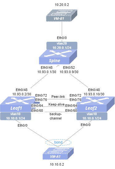
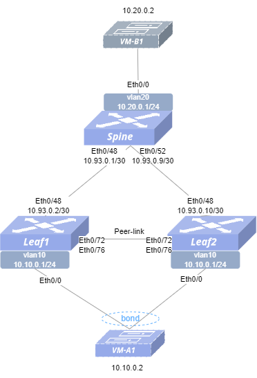
Section titled “Example of a Single Group MC-LAG Configuration”- Networking Requirements In the network, Leaf1 and Leaf2 are two independently operating devices, connected to Spine respectively. Due to the high service reliability requirements of the customer, MC-LAG is required to be configured between Leaf1 and Leaf2 to achieve cross-device link aggregation.
- Topology

- Configuration Roadmap (1) Check that the link status of the ports used on the switch is normal, and that all ports are stable in the UP state. (2) Configure the switch interface IP addresses. (3) Configure VLAN and configure IP address for VLAN interface. (4) Configure link aggregation group and add it to VLAN. (5) Configure MC-LAG. (6) Configure monitor-link-group. (7) Configure static routes to ensure reachability of the service network.
- Procedure Spine Configure IP addresses for interfaces.
interface ethernet 0/48 ip address 10.93.0.1/30 exit!interface ethernet 0/52 ip address 10.93.0.9/30 exit!Configure service VLAN with VLAN-ID 20.
!vlan 20 exit!interface vlan 20 ip address 10.20.0.1/24 exitAdd the interface to the VLAN.
!interface ethernet 0/0 switchport trunk vlan 20Configure static routes
ip route 10.10.0.1/24 10.93.0.2ip route 10.10.0.1/24 10.93.0.10Leaf1 Configure IP addresses for interfaces.
interface ethernet 0/48 ip address 10.93.0.2/30 exitConfigure service VLAN with VLAN-ID 10 and Keep-alive VLAN with VLAN-ID 4094.
vlan 10 exit!vlan 4094 exit!interface vlan 10 ip address 10.10.0.1/24 mac-address 00:00:00:10:00:00 exit!interface vlan 4094 ip address 10.245.0.1/30 exitConfigure LAG.
interface link-aggregation 9999 mode static commit switchport trunk vlan 4094 switchport trunk vlan 10 exit!interface link-aggregation 1 lacp fast-rate commit switchport trunk vlan 10!interface ethernet 0/72 link-aggregation-group 9999 exit!interface ethernet 0/76 link-aggregation-group 9999 exit!interface ethernet 0/0 link-aggregation-group 1 exitConfigure MC-LAG.
mclag domain 1 local-address 10.245.0.1 peer-address 10.245.0.2 peer-link link-aggregation 9999 commit member lag 1Configure Monitor-link
!monitor-link-group MC_LAG 90!interface ethernet 0/48 monitor-link MC_LAG uplink exit!interface ethernet 0/0 monitor-link MC_LAG downlink exitConfigure static routes.
ip route 10.20.0.1/24 10.93.0.1Leaf2 Configure IP addresses for interfaces.
interface ethernet 0/48 ip address 10.93.0.10/30 exitConfigure service VLAN with VLAN-ID 10 and Keep-alive VLAN with VLAN-ID 4094.
vlan 10 exit!vlan 4094 exit!interface vlan 10 ip address 10.10.0.1/24 mac-address 00:00:00:10:00:00 exit!interface vlan 4094 ip address 10.245.0.2/30 exitConfigure LAG.
interface link-aggregation 9999 mode static commit switchport trunk vlan 4094 switchport trunk vlan 10 exit!interface link-aggregation 1 lacp fast-rate commit switchport trunk vlan 10!interface ethernet 0/72 link-aggregation-group 9999 exit!interface ethernet 0/76 link-aggregation-group 9999 exit!interface ethernet 0/0 link-aggregation-group 1 exitConfigure MC-LAG.
mclag domain 1 local-address 10.245.0.2 peer-address 10.245.0.1 peer-link link-aggregation 9999 commit member lag 1Configure Monitor-link
!monitor-link-group MC_LAG 90!interface ethernet 0/48 monitor-link MC_LAG uplink exit!interface ethernet 0/0 monitor-link MC_LAG downlink exitConfigure static routes.
ip route 10.20.0.1/24 10.93.0.9- Verify the configuration.
(1) Check the MC-LAG status (Leaf1).
sonic# show mclag stateThe MCLAG's keepalive is: OKMCLAG info sync is: completedDomain id: 1MCLAG session Channel: Primary ChannelVRF Name: defaultconsistency Check Action: idleLocal Ip: 10.245.0.1Peer Ip: 10.245.0.2Dad Local Ip:Dad Peer Ip:Peer Link Interface: lag 9999Keepalive time: 1Dad Detection Delay: 15Dad Recovery Delay Mlag Intf: 60Dad Recovery Delay Non Mlag Intf: 0Dad VRF Name: defaultDad Status: disablesession Timeout : 15Peer Link Mac: 60:eb:5a:01:10:b1System Mac: 60:eb:5a:01:10:b1Peer Mac: 00:00:00:00:00:00Admin Role: NoneRole: ActiveMCLAG Interface: lag 1Loglevel: NOTICE(2) Verify VM connectivity. VM-A1 and VM-B1 ping each other, can ping through, indicating successful configuration.
Example of MC-LAG ICCP Backup-channel Configuration (keepalive and peer-link are not the same link)
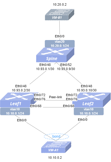
Section titled “Example of MC-LAG ICCP Backup-channel Configuration (keepalive and peer-link are not the same link)”- Networking Requirements In the network, Leaf1 and Leaf2 are two independently operating devices, connected to Spine respectively. Due to the high service reliability requirements of the customer, MC-LAG is required to be configured between Leaf1 and Leaf2 to achieve cross-device link aggregation. Also configure ICCP backup-channel to ensure keep-alive link failure does not affect the work of MC-LAG.
- Topology
- Steps (1)Check that the link status of the ports used on the switch is normal, and that all ports are stable in the UP state. (2)Configure the switch interface IP addresses. (3)Configure VLAN and configure IP address for VLAN interface. (4)Configure link aggregation group and add it to VLAN. (5)Configure MC-LAG. (6)Configure Monitor-link-group. (7)Configure static routes to ensure reachability of the service network.
- Procedure Spine Configure IP addresses for interfaces.
interface ethernet 0/48 ip address 10.93.0.1/30 exit!interface ethernet 0/52 ip address 10.93.0.9/30 exit!Configure service VLAN with VLAN-ID 20.
!vlan 20 exit!interface vlan 20 ip address 10.20.0.1/24 exitAdd the interface to the VLAN.
!interface ethernet 0/0 switchport trunk vlan 20Configure static routes
ip route 10.10.0.1/24 10.93.0.2ip route 10.10.0.1/24 10.93.0.10Leaf1 Configure IP addresses for interfaces.
interface ethernet 0/48 ip address 10.93.0.2/30 exitConfigure service VLAN with VLAN-ID 10, Keep-alive VLAN with VLAN-ID 4094 and ICCP backup VLAN with VLAN-ID 4093.
vlan 10 exit!vlan 4094 exit!vlan 4093 exit!interface vlan 10 ip address 10.10.0.1/24 mac-address 00:00:00:10:00:00 exit!interface vlan 4094 ip address 10.245.0.1/30 exit!interface vlan 4093 exitConfigure LAG.
interface link-aggregation 9999 mode static commit switchport trunk vlan 10 exit!interface link-aggregation 1 lacp fast-rate commit switchport trunk vlan 10!interface ethernet 0/64 switchport trunk vlan 4094!interface ethernet 0/68 switchport trunk vlan 4093!interface ethernet 0/72 link-aggregation-group 9999 exit!interface ethernet 0/76 link-aggregation-group 9999 exit!interface ethernet 0/0 link-aggregation-group 1 exitConfigure MC-LAG.
mclag domain 1 local-address 10.245.0.1 peer-address 10.245.0.2 peer-link link-aggregation 9999 backup-channel vlan 4093 commit member lag 1Configure Monitor-link-group
!monitor-link-group MC_LAG 90!interface ethernet 0/48 monitor-link MC_LAG uplink exit!interface ethernet 0/0 monitor-link MC_LAG downlink exitConfigure static routes.
ip route 10.20.0.1/24 10.93.0.1Leaf2 Configure IP addresses for interfaces.
interface ethernet 0/48 ip address 10.93.0.10/30 exitConfigure service VLAN with VLAN-ID 10, Keep-alive VLAN with VLAN-ID 4094 and ICCP backup VLAN with VLAN-ID 4093.
vlan 10 exit!vlan 4094 exit!vlan 4093 exit!interface vlan 10 ip address 10.10.0.1/24 mac-address 00:00:00:10:00:00 exit!interface vlan 4094 ip address 10.245.0.2/30 exit!interface vlan 4093 exitConfigure LAG.
interface link-aggregation 9999 mode static commit switchport trunk vlan 10 exit!interface link-aggregation 1 lacp fast-rate commit switchport trunk vlan 10!interface ethernet 0/64 switchport trunk vlan 4094!interface ethernet 0/68 switchport trunk vlan 4093!interface ethernet 0/72 link-aggregation-group 9999 exit!interface ethernet 0/76 link-aggregation-group 9999 exit!interface ethernet 0/0 link-aggregation-group 1 exitConfigure MC-LAG.
mclag domain 1 local-address 10.245.0.2 peer-address 10.245.0.1 peer-link link-aggregation 9999 backup-channel vlan 4093 commit member lag 1Configure Monitor-link-group
!monitor-link-group MC_LAG 90!interface ethernet 0/48 monitor-link MC_LAG uplink exit!interface ethernet 0/0 monitor-link MC_LAG downlink exitConfigure static routes.
ip route 10.20.0.1/24 10.93.0.9- Verify the configuration.
(1) Check the MC-LAG status (Leaf1).
sonic# show mclag stateThe MCLAG's keepalive is: OKMCLAG info sync is: completedDomain id: 1MCLAG session Channel: Primary ChannelVRF Name: defaultconsistency Check Action: idleLocal Ip: 10.245.0.1Peer Ip: 10.245.0.2Dad Local Ip:Dad Peer Ip:Peer Link Interface: lag 9999Keepalive time: 1Dad Detection Delay: 15Dad Recovery Delay Mlag Intf: 60Dad Recovery Delay Non Mlag Intf: 0Dad VRF Name: defaultDad Status: disablesession Timeout : 15Peer Link Mac: 60:eb:5a:01:10:b1System Mac: 60:eb:5a:01:10:b1Peer Mac: 00:00:00:00:00:00Admin Role: NoneRole: ActiveMCLAG Interface: lag 1Loglevel: NOTICE(2) Verify VM connectivity. VM-A1 and VM-B1 ping each other, can ping through, indicating successful configuration. (3) Check if the ICCP backup channel is active. Disconnect the keep-alive link and then check the MC-LAG status.
sonic# show mclag stateThe MCLAG's keepalive is: OKMCLAG info sync is: completedDomain id: 1MCLAG session Channel: Backup channel(vlan4093)VRF Name: defaultconsistency Check Action: idleLocal Ip: 10.245.0.1Peer Ip: 10.245.0.2Dad Local Ip:Dad Peer Ip:Peer Link Interface: lag 9999Keepalive time: 1Dad Detection Delay: 15Dad Recovery Delay Mlag Intf: 60Dad Recovery Delay Non Mlag Intf: 0Dad VRF Name: defaultDad Status: disablesession Timeout : 15Peer Link Mac: 60:eb:5a:01:10:b1System Mac: 60:eb:5a:01:10:b1Peer Mac: 00:00:00:00:00:00Admin Role: NoneRole: ActiveMCLAG Interface: lag 1Loglevel: NOTICEExample of MC-LAG scenario loop detection
Section titled “Example of MC-LAG scenario loop detection”- Topology
- Configuration Roadmap (1) Check that the link status of the ports used on the switch is normal, and that all ports are stable in the UP state. (2) Configure the switch interface IP addresses. (3) Configure VLAN and configure IP address for VLAN interface. (4) Configure link aggregation group and add it to VLAN. (5) Configure MC-LAG. (6) Configure loop detection on the interface (7) Configure static routes to ensure reachability of the service network
- Procedure Spine Configure IP addresses for interfaces.
interface ethernet 0/48 ip address 10.93.0.1/30 exit!interface ethernet 0/52 ip address 10.93.0.9/30 exit!Configure service VLAN with VLAN-ID 20.
!vlan 20 exit!interface vlan 20 ip address 10.20.0.1/24 exitAdd the interface to the VLAN.
!interface ethernet 0/0 switchport trunk vlan 20Configure static routes.
ip route 10.10.0.1/24 10.93.0.2ip route 10.10.0.1/24 10.93.0.10Leaf1 Configure IP addresses for interfaces.
interface ethernet 0/48 ip address 10.93.0.2/30 exitConfigure service VLAN with VLAN-ID 10, Keep-alive VLAN with VLAN-ID 4094.
vlan 10 exit!vlan 4094 exit!interface vlan 10 ip address 10.10.0.1/24 mac-address 00:00:00:10:00:00 exit!interface vlan 4094 ip address 10.245.0.1/30 exitConfigure LAG.
interface link-aggregation 9999 mode static commit switchport trunk vlan 4094 switchport trunk vlan 10 exit!interface link-aggregation 1 lacp fast-rate commit switchport trunk vlan 10!interface ethernet 0/68 switchport trunk vlan 10!interface ethernet 0/72 link-aggregation-group 9999 exit!interface ethernet 0/76 link-aggregation-group 9999 exit!interface ethernet 0/0 link-aggregation-group 1 exitConfigure MC-LAG.
mclag domain 1 local-address 10.245.0.1 peer-address 10.245.0.2 peer-link link-aggregation 9999 commit member lag 1Configure loopback detection on the interface.
!interface link-aggregation 1 loopback-detect vlan 10-40 policy block-vlan interval 20 wait-time 60Configure static routes.
ip route 10.20.0.1/24 10.93.0.1Leaf2 Configure IP addresses for interfaces.
interface ethernet 0/48 ip address 10.93.0.10/30 exitConfigure service VLAN with VLAN-ID 10, Keep-alive VLAN with VLAN-ID 4094.
vlan 10 exit!vlan 4094 exit!interface vlan 10 ip address 10.10.0.1/24 mac-address 00:00:00:10:00:00 exit!interface vlan 4094 ip address 10.245.0.2/30 exitConfigure LAG.
interface link-aggregation 9999 mode static commit switchport trunk vlan 4094 switchport trunk vlan 10 exit!interface link-aggregation 1 lacp fast-rate commit switchport trunk vlan 10!interface ethernet 0/68 switchport trunk vlan 10!interface ethernet 0/72 link-aggregation-group 9999 exit!interface ethernet 0/76 link-aggregation-group 9999 exit!interface ethernet 0/0 link-aggregation-group 1 exitConfigure MC-LAG.
mclag domain 1 local-address 10.245.0.2 peer-address 10.245.0.1 peer-link link-aggregation 9999 commit member lag 1Configure loopback detection on the interface.
!interface link-aggregation 1 loopback-detect vlan 10-40 policy block-vlan interval 20 wait-time 60Configure static routes.
ip route 10.20.0.1/24 10.93.0.9- Verify the configuration.
(1) Check the MC-LAG status (Leaf1).
sonic# show mclag stateThe MCLAG's keepalive is: OKMCLAG info sync is: completedDomain id: 1MCLAG session Channel: Primary ChannelVRF Name: defaultconsistency Check Action: idleLocal Ip: 10.245.0.1Peer Ip: 10.245.0.2Dad Local Ip:Dad Peer Ip:Peer Link Interface: lag 9999Keepalive time: 1Dad Detection Delay: 15Dad Recovery Delay Mlag Intf: 60Dad Recovery Delay Non Mlag Intf: 0Dad VRF Name: defaultDad Status: disablesession Timeout : 15Peer Link Mac: 60:eb:5a:01:10:b1System Mac: 60:eb:5a:01:10:b1Peer Mac: 00:00:00:00:00:00Admin Role: NoneRole: ActiveMCLAG Interface: lag 1Loglevel: NOTICE(2) Check the loop detection results.
sonic# show loopback-detectPort Policy Vlan Interval Wait time Vlans with loop------ ---------- ------ ---------- ----------- -----------------lag1 block-vlan 10-40 20 60 10Example of Two-Level MC-LAG Configuration
Section titled “Example of Two-Level MC-LAG Configuration”- Networking Requirements The customer needs to build a large Layer 2 data center network using a two-level MC-LAG approach to expand the number of accessible hosts.
- Topology
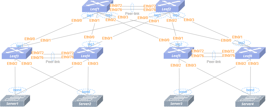
- Configuration Roadmap (1) Check that the link status of the ports used on the switch is normal, and that all ports are stable in the UP state. (2) Configure VLAN and configure IP address for VLAN interface. (3) Configure link aggregation group and add it to VLAN. (4) Configure MC-LAG.
- Procedure Leaf1 Configure service VLAN with VLAN-ID 10, Keep-alive VLAN with VLAN-ID 4094.
vlan 10 exit!vlan 4094 exit!interface vlan 10 ip address 10.10.0.1/24 mac-address 00:00:00:10:00:00 exit!interface vlan 4094 ip address 10.245.0.1/30 exitConfigure LAG.
interface link-aggregation 9999 mode static commit switchport trunk vlan 4094 switchport trunk vlan 10 exit!interface link-aggregation 1 lacp fast-rate commit switchport trunk vlan 10!interface link-aggregation 2 lacp fast-rate commit switchport trunk vlan 10!interface ethernet 0/72 link-aggregation-group 9999 exit!interface ethernet 0/76 link-aggregation-group 9999 exit!interface ethernet 0/0 link-aggregation-group 1 exit!interface ethernet 0/1 link-aggregation-group 1 exit!interface ethernet 0/2 link-aggregation-group 2 exit!interface ethernet 0/3 link-aggregation-group 2 exitConfigure MC-LAG
mclag domain 1 local-address 10.245.0.1 peer-address 10.245.0.2 peer-link link-aggregation 9999 commit member lag 1 member lag 2Leaf2 Configure service VLAN with VLAN-ID 10, Keep-alive VLAN with VLAN-ID 4094.
vlan 10 exit!vlan 4094 exit!interface vlan 10 ip address 10.10.0.1/24 mac-address 00:00:00:10:00:00 exit!interface vlan 4094 ip address 10.245.0.2/30 exitConfigure LAG.
interface link-aggregation 9999 mode static commit switchport trunk vlan 4094 switchport trunk vlan 10 exit!interface link-aggregation 1 lacp fast-rate commit switchport trunk vlan 10!interface link-aggregation 2 lacp fast-rate commit switchport trunk vlan 10!interface ethernet 0/72 link-aggregation-group 9999 exit!interface ethernet 0/76 link-aggregation-group 9999 exit!interface ethernet 0/0 link-aggregation-group 1 exit!interface ethernet 0/1 link-aggregation-group 1 exit!interface ethernet 0/2 link-aggregation-group 2 exit!interface ethernet 0/3 link-aggregation-group 2 exitConfigure MC-LAG
mclag domain 1 local-address 10.245.0.2 peer-address 10.245.0.1 peer-link link-aggregation 9999 commit member lag 1 member lag 2Leaf3 Configure service VLAN with VLAN-ID 10, Keep-alive VLAN with VLAN-ID 4094.
vlan 10 exit!vlan 4094 exit!interface vlan 4094 ip address 10.245.0.5/30 exitConfigure LAG.
interface link-aggregation 9999 mode static commit switchport trunk vlan 4094 switchport trunk vlan 10 exit!interface link-aggregation 1 lacp fast-rate commit switchport trunk vlan 10!interface link-aggregation 100 lacp fast-rate commit switchport trunk vlan 10!interface link-aggregation 101 lacp fast-rate commit switchport trunk vlan 10!interface ethernet 0/72 link-aggregation-group 9999 exit!interface ethernet 0/76 link-aggregation-group 9999 exit!interface ethernet 0/0 link-aggregation-group 1 exit!interface ethernet 0/1 link-aggregation-group 1 exit!interface ethernet 0/2 link-aggregation-group 100 exit!interface ethernet 0/3 link-aggregation-group 101 exitConfigure MC-LAG
mclag domain 1 local-address 10.245.0.5 peer-address 10.245.0.6 peer-link link-aggregation 9999 commit member lag 1 member lag 100 member lag 101Leaf4 Configure service VLAN with VLAN-ID 10, Keep-alive VLAN with VLAN-ID 4094.
vlan 10 exit!vlan 4094 exit!interface vlan 4094 ip address 10.245.0.6/30 exitConfigure LAG.
interface link-aggregation 9999 mode static commit switchport trunk vlan 4094 switchport trunk vlan 10 exit!interface link-aggregation 1 lacp fast-rate commit switchport trunk vlan 10!interface link-aggregation 100 lacp fast-rate commit switchport trunk vlan 10!interface link-aggregation 101 lacp fast-rate commit switchport trunk vlan 10!interface ethernet 0/72 link-aggregation-group 9999 exit!interface ethernet 0/76 link-aggregation-group 9999 exit!interface ethernet 0/0 link-aggregation-group 1 exit!interface ethernet 0/1 link-aggregation-group 1 exit!interface ethernet 0/2 link-aggregation-group 100 exit!interface ethernet 0/3 link-aggregation-group 101 exitConfigure MC-LAG
mclag domain 1 local-address 10.245.0.6 peer-address 10.245.0.5 peer-link link-aggregation 9999 commit member lag 1 member lag 100 member lag 101Leaf5 Configure service VLAN with VLAN-ID 10, Keep-alive VLAN with VLAN-ID 4094.
vlan 10 exit!vlan 4094 exit!interface vlan 4094 ip address 10.245.0.9/30 exitConfigure LAG.
interface link-aggregation 9999 mode static commit switchport trunk vlan 4094 switchport trunk vlan 10 exit!interface link-aggregation 2 lacp fast-rate commit switchport trunk vlan 10!interface link-aggregation 100 lacp fast-rate commit switchport trunk vlan 10!interface link-aggregation 101 lacp fast-rate commit switchport trunk vlan 10!interface ethernet 0/72 link-aggregation-group 9999 exit!interface ethernet 0/76 link-aggregation-group 9999 exit!interface ethernet 0/0 link-aggregation-group 2 exit!interface ethernet 0/1 link-aggregation-group 2 exit!interface ethernet 0/2 link-aggregation-group 100 exit!interface ethernet 0/3 link-aggregation-group 101 exitConfigure MC-LAG
mclag domain 1 local-address 10.245.0.9 peer-address 10.245.0.10 peer-link link-aggregation 9999 commit member lag 2 member lag 100 member lag 101Leaf6 Configure service VLAN with VLAN-ID 10, Keep-alive VLAN with VLAN-ID 4094.
vlan 10 exit!vlan 4094 exit!interface vlan 4094 ip address 10.245.0.10/30 exitConfigure LAG.
interface link-aggregation 9999 mode static commit switchport trunk vlan 4094 switchport trunk vlan 10 exit!interface link-aggregation 2 lacp fast-rate commit switchport trunk vlan 10!interface link-aggregation 100 lacp fast-rate commit switchport trunk vlan 10!interface link-aggregation 101 lacp fast-rate commit switchport trunk vlan 10!interface ethernet 0/72 link-aggregation-group 9999 exit!interface ethernet 0/76 link-aggregation-group 9999 exit!interface ethernet 0/0 link-aggregation-group 2 exit!interface ethernet 0/1 link-aggregation-group 2 exit!interface ethernet 0/2 link-aggregation-group 100 exit!interface ethernet 0/3 link-aggregation-group 101 exitConfigure MC-LAG
mclag domain 1 local-address 10.245.0.10 peer-address 10.245.0.9 peer-link link-aggregation 9999 commit member lag 2 member lag 100 member lag 101- Verify the configuration.
(1) Check the MC-LAG status (Leaf1)
sonic# show mclag stateThe MCLAG's keepalive is: OKMCLAG info sync is: completedDomain id: 1MCLAG session Channel: Primary ChannelVRF Name: defaultconsistency Check Action: idleLocal Ip: 10.245.0.1Peer Ip: 10.245.0.2Dad Local Ip:Dad Peer Ip:Peer Link Interface: lag 9999Keepalive time: 1Dad Detection Delay: 15Dad Recovery Delay Mlag Intf: 60Dad Recovery Delay Non Mlag Intf: 0Dad VRF Name: defaultDad Status: disablesession Timeout : 15Peer Link Mac: 60:eb:5a:01:10:b1System Mac: 60:eb:5a:01:10:b1Peer Mac: 18:45:85:98:43:9bAdmin Role: NoneRole: ActiveMCLAG Interface: lag 1Loglevel: NOTICE(2) Verify Server connectivity. Configure IPs for the Servers within the subnet of VLAN 10: assign 10.10.0.11 to Server1, 10.10.0.12 to Server2, 10.10.0.13 to Server3, and 10.10.0.14 to Server4. Server1, Server2, Server3, Server4, ping each other, can ping through, indicating successful configuration.
Example of MC-LAG L3 Backup Link Configuration
Section titled “Example of MC-LAG L3 Backup Link Configuration”- Networking Requirements In the network, Leaf1 and Leaf2 are two independently operating devices, connected to Spine respectively. Due to the high service reliability requirements of the customer, MC-LAG is required to be configured between Leaf1 and Leaf2 to achieve cross-device link aggregation. An additional L3 backup link needs to be configured to ensure that traffic can be forwarded normally in the event of an uplink failure.
- Topology
- Configuration Roadmap (1) Check that the link status of the ports used on the switch is normal, and that all ports are stable in the UP state. (2) Configure the switch interface IP addresses. (3) Configure VLAN and configure IP address for VLAN interface. (4) Configure link aggregation group and add it to VLAN. (5) Configure MC-LAG. (6) Configure L3 backup link. (7) Configure static routes to ensure reachability of the service network
- Procedure Spine Configure IP addresses for interfaces.
interface ethernet 0/48 ip address 10.93.0.1/30 exit!interface ethernet 0/52 ip address 10.93.0.9/30 exit!Configure service VLAN with VLAN-ID 20.
!vlan 20 exit!interface vlan 20 ip address 10.20.0.1/24 exitAdd the interface to the VLAN.
!interface ethernet 0/0 switchport trunk vlan 20Configure static routes.
ip route 10.10.0.1/24 10.93.0.2ip route 10.10.0.1/24 10.93.0.10Leaf1 Configure IP addresses for interfaces.
interface ethernet 0/48 ip address 10.93.0.2/30 exitConfigure service VLAN with VLAN-ID 10 and Keep-alive VLAN with VLAN-ID 4094.
vlan 10 exit!vlan 4094 exit!interface vlan 10 ip address 10.10.0.1/24 mac-address 00:00:00:10:00:00 exit!interface vlan 4094 ip address 10.245.0.1/30 exitConfigure LAG.
interface link-aggregation 9999 mode static commit switchport trunk vlan 4094 switchport trunk vlan 10 exit!interface link-aggregation 1 lacp fast-rate commit switchport trunk vlan 10!interface ethernet 0/72 link-aggregation-group 9999 exit!interface ethernet 0/76 link-aggregation-group 9999 exit!interface ethernet 0/0 link-aggregation-group 1 exitConfigure MC-LAG.
mclag domain 1 local-address 10.245.0.1 peer-address 10.245.0.2 peer-link link-aggregation 9999 commit member lag 1Configure static routes.
ip route 10.20.0.1/24 10.93.0.1Configure L3 backup link
!interface vlan 4094 ip ospf bfd ip ospf network point-to-point exit!ospf enable!router ospf network 10.245.0.1/30 area 0.0.0.0 network 10.20.0.1/24 area 0.0.0.0Leaf2 Configure IP addresses for interfaces.
interface ethernet 0/48 ip address 10.93.0.10/30 exitConfigure service VLAN with VLAN-ID 10 and Keep-alive VLAN with VLAN-ID 4094.
vlan 10 exit!vlan 4094 exit!interface vlan 10 ip address 10.10.0.1/24 mac-address 00:00:00:10:00:00 exit!interface vlan 4094 ip address 10.245.0.2/30 exitConfigure LAG.
interface link-aggregation 9999 mode static commit switchport trunk vlan 4094 switchport trunk vlan 10 exit!interface link-aggregation 1 lacp fast-rate commit switchport trunk vlan 10!interface ethernet 0/72 link-aggregation-group 9999 exit!interface ethernet 0/76 link-aggregation-group 9999 exit!interface ethernet 0/0 link-aggregation-group 1 exitConfigure MC-LAG.
mclag domain 1 local-address 10.245.0.2 peer-address 10.245.0.1 peer-link link-aggregation 9999 commit member lag 1Configure static routes.
ip route 10.20.0.1/24 10.93.0.9Configure L3 backup link
!interface vlan 4094 ip ospf bfd ip ospf network point-to-point!ospf enable!router ospf network 10.245.0.2/30 area 0.0.0.0 network 10.20.0.1/24 area 0.0.0.0- Verify the configuration. (1) Check the MC-LAG status (Leaf1).
sonic# show mclag stateThe MCLAG's keepalive is: OKMCLAG info sync is: completedDomain id: 1MCLAG session Channel: Primary ChannelVRF Name: defaultconsistency Check Action: idleLocal Ip: 10.245.0.1Peer Ip: 10.245.0.2Dad Local Ip:Dad Peer Ip:Peer Link Interface: lag 9999Keepalive time: 1Dad Detection Delay: 15Dad Recovery Delay Mlag Intf: 60Dad Recovery Delay Non Mlag Intf: 0Dad VRF Name: defaultDad Status: disablesession Timeout : 15Peer Link Mac: 60:eb:5a:01:10:b1System Mac: 60:eb:5a:01:10:b1Peer Mac: 00:00:00:00:00:00Admin Role: NoneRole: ActiveMCLAG Interface: lag 1Loglevel: NOTICE(2) Verify VM connectivity. VM-A1 and VM-B1 ping each other, can ping through, indicating successful configuration