
VRRP SYNC GROUP Configuration Guide
Introduction
Section titled “Introduction”In the standard RFC protocol, VRRP operates independently based on a single interface or VLAN. Each VRRP backup group (VRID) on the device has an independent state machine that sends and receives VRRP advertisement messages, independently calculates priorities, and elects a Master. VRRP Sync Group is a logical management hierarchy built on top of standard VRRP. Its essence is to deprive a single VRRP instance of its “independent decision-making power”. Once multiple VRRP instances are added to the same synchronization group, they are no longer scattered but form a “logical gateway entity”. Within this entity, the states of all members must maintain absolute strong consistency.
Explanation of Principles
Section titled “Explanation of Principles”Basic Concepts
Section titled “Basic Concepts”In complex multi service gateway scenarios (such as dual link access between firewall and intranet), if each VRRP instance (backup group) on the device runs independently, when a link on one side (such as an intranet link) fails, only the VRRP on that side will switch between primary and backup, which will result in inconsistent upstream and downstream traffic paths (asymmetric routing), leading to business interruption. The VRRP Sync Group aims to address this issue. It allows administrators to join multiple VRRP instances on the same device with different interfaces into the same logical group (Sync Group, ID range 1-255) for collaborative management. The core idea is to bundle the interface states of all VRRP instances within the group. As long as any interface within the group fails, all VRRP instances in the group will receive a unified “Priority Decrement”, triggering a global synchronous master-slave switch to ensure that the gateways of multiple business links always reside on the same physical device.
VRRP synchronization group status binding and monitoring
Section titled “VRRP synchronization group status binding and monitoring”When a VRRP instance is added to a synchronization group through configuration (such as vrrp 1 sync group 1 priority dec 20) under the interface, the physical or logical interface bound to the VRRP instance automatically becomes the monitoring interface (Track interface) of the synchronization group. The synchronization group manager will monitor the UP/DOWN status of all Track interfaces within the group in real-time.
VRRP Synchronization Group Fault Switching and Global Downgrading
Section titled “VRRP Synchronization Group Fault Switching and Global Downgrading”When the physical state or link protocol state of any Track interface in the synchronization group changes to DOWN, the synchronization group manager will immediately take action by uniformly deducting the configured attenuation value (i.e. the size of priority dec, ranging from 10 to 50) from the current priority of all VRRP instances in the synchronization group. During the attenuation process, if the priority after deduction is lower than 1, the system will automatically keep it at a minimum of 1 to maintain the basic VRRP protocol operation. With the sudden drop in group priority, all VRRP instances of devices that were originally in the Master state will have lower priority than the backup devices on the other end. After receiving a low priority VRRP notification message, all VRRP instances on the backup device will trigger preemption simultaneously, collectively upgrading to Master, thus achieving seamless synchronization and lossless takeover of multi network segment business traffic.
VRRP synchronization group fault recovery and switching back
Section titled “VRRP synchronization group fault recovery and switching back”When the failed Track interface link status returns to UP, the synchronization group manager will lift the priority penalty. The priority of all VRRP instances within the group will be synchronously increased by the value of priority dec until it returns to the initial configuration value before the failure. After priority restoration, if the initial priority of the device is higher than that of the current Master device and Preempt mode is configured, all VRRP instances on the device will synchronize and regain the Master state again. Note that VRRPs that have joined the VRRP synchronization group must be configured in preemption mode.
VRRP synchronization group configuration constraints and precautions
Section titled “VRRP synchronization group configuration constraints and precautions”Due to the fact that synchronization groups operate based on uniform priority decay, the following rules must be followed during configuration:
- Consistency of attenuation step size: All VRRP instances added to the same Sync Group must have identical priority dec values configured. Only by keeping the attenuation step consistent can we ensure that the priority of all instances in the group synchronously decreases in the event of a failure, avoiding the phenomenon of partial switching and partial non switching “brain cracking” within the group.
- Reasonable planning of initial priority and attenuation values: Administrators must meet the formula when planning: (Master initial priority) - (priority dec decay value)<(Backup initial priority) For example, the primary device configuration priority is 120, and the backup device configuration is 100. So the priority dec needs to be set to at least 21 or above (it is recommended to set it to 30). In this way, when the link on the main device side fails, the priority of the entire group becomes 120-30=90, which is lower than 100 for the backup machine, in order to successfully trigger the entire group switch.
VRRP SYNC GROUP Configuration
Section titled “VRRP SYNC GROUP Configuration”Create VRRP
Section titled “Create VRRP”| Operation | Command | Description |
|---|---|---|
| Enter the interface configuration view | interface Ethernet|vlan id | |
| Create VRRP | vrrp <id> | |
| Configure VRRP virtual IP address | vrrp <id> ip/ipv6 <A.B.C.D/M|A::B/M> | ID: Value range 1-255 |
Configure VRRP to join SYNC GROUP
Section titled “Configure VRRP to join SYNC GROUP”| Operation | Command | Description |
|---|---|---|
| Enter the interface configuration view | interface Ethernet|vlan id | |
| Configure VRRP synchronization group | vrrp <id> sync-group <id> priority-dec <number> | ID: Value range 1-255 |
Configure VRRP recovery delay
Section titled “Configure VRRP recovery delay”| Operation | Command | Description |
|---|---|---|
| Enter the interface configuration view | interface Ethernet|vlan id | |
| Configure VRRP recovery delay | vrrp <id> startup-delay <time> | Time: VRRP recovery delay (s), used to synchronize the priority of track interfaces within the group after recovery, triggering a backup switch to the main mode. After waiting for the startup delay time, load VRRP related configurations first before performing the main backup switch to avoid the inability to process traffic in a timely manner |
Configure the track interface for VRRP
Section titled “Configure the track interface for VRRP”| Operation | Command | Description |
|---|---|---|
| Enter the interface configuration view | interface Ethernet|vlan id | |
| Configure the track interface for VRRP | vrrp <id> track-interface [ethernet|vlan|lag] <name> priority-dec <number> | Used to specify the monitoring port corresponding to a VRRP, and to promptly downgrade/upgrade it when the corresponding track interface link status changes. Name: Configure the interface name for track interface Number: Priority decay value, with a configuration range of 10-50 |
Display and Maintenance
Section titled “Display and Maintenance”| Operation | Command |
|---|---|
| Synchronize the display of SYNC GROUP information under VRRP detailed information | show vrrp <id> |
Configuration Example
Section titled “Configuration Example”Network Requirements
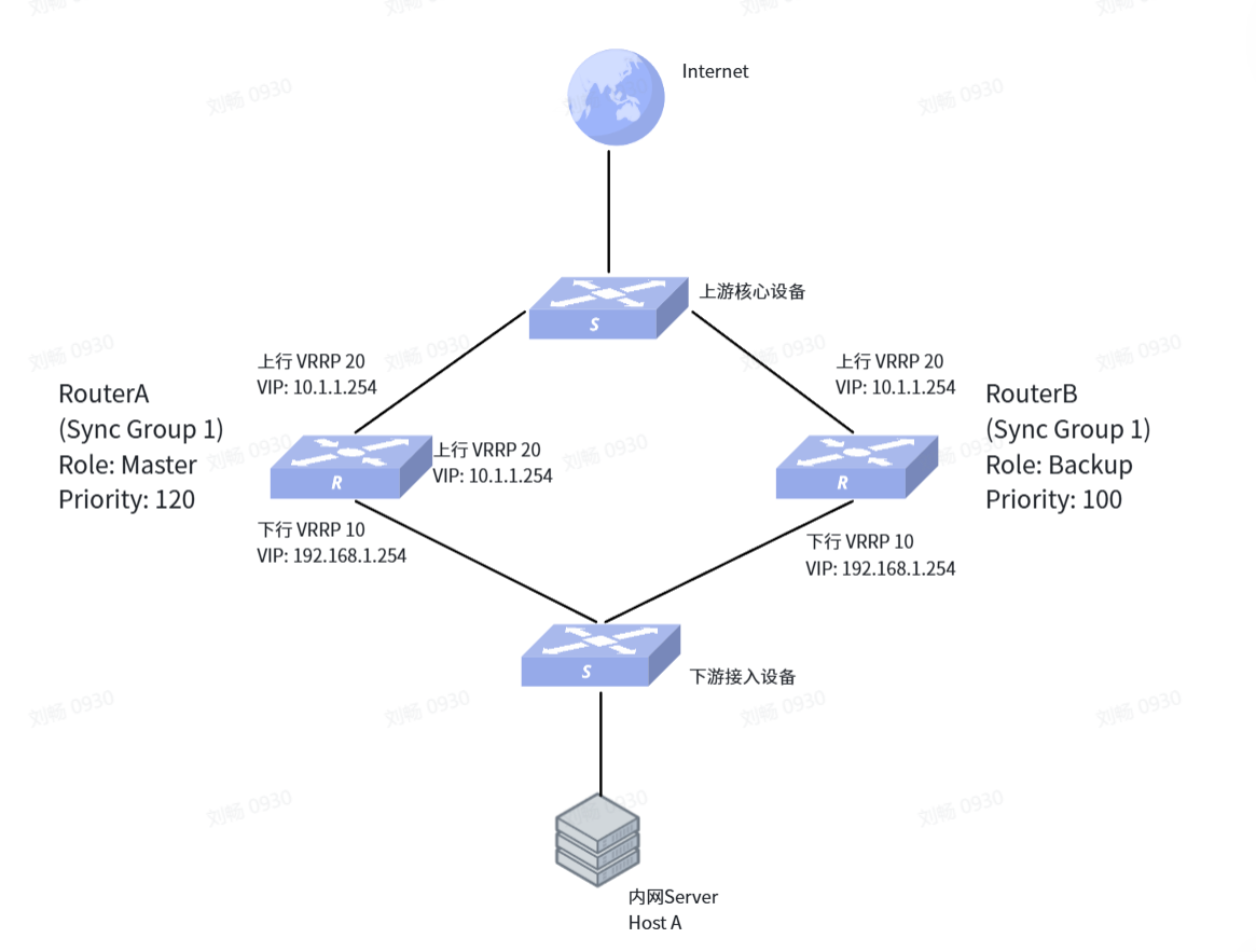
As shown in the networking diagram, the internal network user (Host A) belongs to the gateway devices Router A and Router B through the downstream access switch. Router A and Router B are connected to the upstream core switch through the uplink and lead to the Internet. High availability requirement: To ensure high reliability of the business, VRRP is deployed on Router A and Router B. Downstream configuration of VRRP 10 for the internal network (virtual IP 192.168.1.254 as the internal network gateway); Upstream configuration of VRRP 20 towards the core network (virtual IP 10.1.1.254 as the external gateway). Synchronization switching requirement: Under normal circumstances, Router A is required to handle all incoming and outgoing gateway traffic uniformly. In order to prevent message back and forth path inconsistency (asymmetric routing) caused by link failure on either side, VRRP 10 and VRRP 20 on the device need to be added to the same VRRP synchronization group. When the upstream or downstream interface of Router A fails, it triggers the priority decay penalty of the synchronization group, allowing Router B to synchronously take over the gateway services of the internal and external networks, ensuring uninterrupted business.
Procedure
# Device A
1. Configure downstream interface and VRRP 10sonic(config)# interface Vlan 10sonic(config-if-Vlan10)# ip address 192.168.1.2/24sonic(config-if-Vlan10)# vrrp 10 ip 192.168.1.254/24sonic(config-if-Vlan10)# vrrp 10 priority 120Add VRRP 10 to synchronization group 1 and set the priority penalty value to 30sonic(config-if-Vlan10)# vrrp 10 sync-group 1 priority-dec 30sonic(config-if-Vlan10)# exit2. Configure uplink interface and VRRP 20sonic(config)# interface vlan 20sonic(config-if-Vlan20)# ip address 10.1.1.2/24sonic(config-if-Vlan20)# vrrp 20 ip 10.1.1.254/24sonic(config-if-Vlan20)# vrrp 20 priority 120Add VRRP 20 to synchronization group 1, and the penalty value must be consistent with other instances in the same groupsonic(config-if-Vlan20)# vrrp 20 sync-group 1 priority-dec 30sonic(config-if-Vlan20)# exit#Device B
1. Configure downstream interface and VRRP 10sonic(config)# interface Vlan 10sonic(config-if-Vlan10)# ip address 192.168.1.3/24sonic(config-if-Vlan10)# vrrp 10 ip 192.168.1.254/24sonic(config-if-Vlan10)# vrrp 10 priority 100Add VRRP 10 to synchronization group 1 and set the priority penalty value to 30sonic(config-if-Vlan10)# vrrp 10 sync-group 1 priority-dec 30sonic(config-if-Vlan10)# exit2. Configure uplink interface and VRRP 20sonic(config)# interface vlan 20sonic(config-if-Vlan20)# ip address 10.1.1.3/24sonic(config-if-Vlan20)# vrrp 20 ip 10.1.1.254/24sonic(config-if-Vlan20)# vrrp 20 priority 100Add VRRP 20 to synchronization group 1, and the penalty value must be consistent with other instances in the same groupsonic(config-if-Vlan20)# vrrp 20 sync-group 1 priority-dec 30sonic(config-if-Vlan20)# exitExpected result
1.Normal operating state: After configuration is completed, Router A’s VRRP 10 and VRRP 20 become Masters with a high priority of 120. The upstream and downstream traffic of internal network users is uniformly forwarded by Router A. All VRRP instances of Router B are in Backup state.
2.Fault degradation stage: When the upstream interface (Vlan 20) of Router A changes to the DOWN state due to a physical line fault: VRRP 20 of Router A is unable to continue working and the state machine has changed to Initialize. Synchronization group 1 detected a member interface failure and immediately imposed punishment on VRRP 10 in the same group, reducing its priority from 120 by 30 to 90.
3.Handover phase: After receiving the VRRP notification message with priority of 90, VRRP 10 of Router B found that its priority (100) was better and immediately triggered preemption to become the Master; At the same time, VRRP 20 of Router B also became a Master due to the end stop notification. At this point, the upstream and downstream gateways have successfully synchronized and migrated to Router B.
4.Fault recovery and switching back: When the uplink interface link of Router A is restored to UP, synchronization group 1 is released from punishment, Router A’s priority is raised to 120, and the Master role of the entire group is regained, resulting in smooth traffic switching back to the main device.