
IS-IS Configuration Guide
此内容尚不支持你的语言。
Introduction
Section titled “Introduction”IS-IS (Intermediate System to Intermediate System) is a dynamic routing protocol designed by the International Organization for Standardization (ISO) for its connectionless network protocol CLNP (Connect Less Network Protocol). It is an internal gateway protocol (IGP) based on link state, used for routing exchange within autonomous systems. IS-IS operates at the data link layer and uses the Shortest Path First (SPF) algorithm for routing calculations. It has the advantages of fast convergence, strong scalability, strong resistance to attacks, and can achieve interoperability in large-scale networks. With the widespread application of the TCP/IP protocol, the IETF organization expanded and modified IS-IS in RFC1195, enabling it to be applied simultaneously in both TCP/IP and OSI (Open System Interconnection) environments, known as Integrated IS-IS or Dual IS-IS.
Basic Concepts
Section titled “Basic Concepts”IS-IS area
Section titled “IS-IS area”IS-IS adopts a hierarchical structure of backbone and non backbone regions within the autonomous system. Level-1 routers are deployed in non backbone areas, while Level-2 routers and Level-1-2 routers are deployed in backbone areas. Each non backbone area is connected to the backbone area through Level-1-2 routers. Area differences between IS-IS and OSPF:
- All interfaces of a single router in IS-IS belong to the same area. Different interfaces of a single router in OSPF can belong to different regions.
- In IS-IS, there is no distinction between backbone and non backbone areas for a single region. Backbone area in OSPF refers to the area with Area 0.
- Both Level-1 and Level-2 routing in IS-IS use SPF algorithm to generate Shortest Path Tree (SPT) for each level. In OSPF, the SPF algorithm is only used within the same area, and routing between areas needs to be forwarded through the backbone area.
IS-IS router type
Section titled “IS-IS router type”There are three different routers in IS-IS network: Level-1,Level-2,Level-1-2.
- Level-1 router: responsible for routing within the region, it only forms neighbor relationships with Level-1 and Level-1-2 routers belonging to the same region. A Level-1 router is only responsible for maintaining the LSDB (Link State Database) within its own area. For routes whose destination is not within its own area, the Level-1 router will identify the destination as the nearest Level-1-2 router.
- Level-2 router: responsible for routing between regions, can form neighbor relationships with Level-2 or Level-1-2 routers in other regions, and maintain a Level-2 LSDB that contains routing information between regions. All Level-2 level routers form the backbone network of the routing domain, responsible for communication between different areas. Level-2 level routers in the routing domain must be physically continuous to ensure the continuity of the backbone network. Only Level-2 level routers can directly exchange data packets or routing information with routers outside the region.
- Level-1-2 router: A router that belongs to both Level-1 and Level-2 is called a Level-1-2 router. It can form a Level-1 neighbor relationship with Level-1 and Level-1-2 routers in the same area, or form a Level-2 neighbor relationship with Level-2 and Level-1-2 routers in other areas. Level-1 routers must pass through Level-1-2 routers to connect to other areas. Level-1-2 routers maintain two LSDBs, with Level-1 LSDB used for intra area routing and Level-2 LSDB used for inter area routing.
IS-IS network type
Section titled “IS-IS network type”IS-IS supports two types of networks, which can be divided into broadcast networks and point-to-point networks based on different physical links.
- Broadcast network: running on broadcast links such as Ethernet, Token Ring, etc.
- Point to point network: runs on point-to-point links such as PPP, HDLC, etc. In broadcast networks, IS-IS needs to select one router from all routers as the Designated Intermediate System (DIS). DIS is used to create and update pseudo nodes, and is responsible for generating Link State Protocol Data Units (LSPs) for pseudo nodes, which describe the network devices on this network. Pseudo nodes are virtual nodes used to simulate broadcast networks, not real routers. In IS-IS, pseudo nodes are identified by the System ID of DIS and a byte of Circuit ID (non-zero value). Level-1 and Level-2 DIS are elected separately, and users can set different priorities for DIS elections at different levels. The one with the highest DIS priority value is selected as DIS. If there are multiple routers with the highest priority value, the router with the highest MAC address will be selected. Different levels of DIS can be the same router or different routers. Differences between IS-IS DIS and OSPF DR:
- In the IS-IS broadcast network, routers with priority 0 participate in the election of DIS. Routers with priority 0 in OSPF do not participate in DR elections.
- In the IS-IS broadcast network, when a newly added router meets the conditions to become a DIS, it will be selected as the new DIS, and the original pseudo nodes will be deleted. This change will cause a new set of LSPs to flood. In OSPF, a newly added router will not immediately become a DR in the network even if it has the highest DR priority value.
- In the IS-IS broadcast network, adjacency relationships are formed between routers of the same level on the same network segment, including all non DIS routers. In OSPF, routers only establish adjacency relationships with DR and BDR
IS-IS NET identifier
Section titled “IS-IS NET identifier”Network Service Access Point (NSAP) is an address used in the OSI protocol to locate resources, and its structure is shown in the following figure.
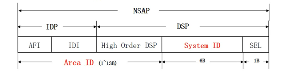
IDP (Initial Domain Part) consists of two parts: AFI (Authority and Format Identifier) and IDI (Initial Domain Identifier). AFI stands for Address Allocation Authority and Address Format, while IDI is used to identify domains. The DSP (Domain Specific Part) consists of three parts: High Order DSP, System ID, and SEL. High Order DSP is used to divide regions, System ID is used to distinguish hosts, and SEL (NSAP selector) is used to indicate service types. Area Address is composed of IDP and High Order DSP in DSP, equivalent to Area ID in OSPF. All routing devices within the same Level-1 area must have the same area address, while routing devices within Level-2 area can have different area addresses. The System ID is used to uniquely identify a host or routing device within a region, and in device implementation, its length is fixed at 48 bits (6 bytes). In practical use, the following method can be used to correspond to the device Router ID and System ID: Expand each part of IP address 10.1.0.1 to 3 bits, i.e. 010.001.000.001, and redivide the extended port address into 3 parts to obtain 0100.0100.0001 as the System ID. SEL(NSAP Selector),Similar to the IP protocol field in the IP protocol, SEL is 00 in the IP network. NET (Network Entity Title) is a special type of NSAP (SEL=00) that uniquely identifies routers in IS-IS networks.
IS-IS message type
Section titled “IS-IS message type”IS-IS defines 9 types of PDUs, which can be divided 3 categories based on their functions: Hello, LSP, SNP.
Table 1 IS-IS message type
| IS-IS message | PDU type | PDU Type value | Description |
|---|---|---|---|
| Hello | L1 Hello | 15 | Used to establish Level-1 neighbors on broadcast type links |
| L2 Hello | 16 | Used to establish Level-2 neighbors on broadcast type links | |
| P2P Hello | 17 | Used to establish Level-1 and Level-2 neighbors on point-to-point links | |
| LSP | L1 LSP | 18 | Used to describe the link status table of non backbone areas |
| L2 LSP | 20 | Used to describe the status table of backbone area links | |
| SNP | L1 CSNP | 24 | L1 level complete sequence number PDU, similar to OSPF DD message |
| L2 CSNP | 25 | L2 level complete sequence number PDU, similar to OSPF DD message | |
| L1 PSNP | 26 | Partial sequence number PDU at L1 level, similar to OSPF’s LSR and LSACK | |
| L2 PSNP | 27 | Partial sequence number PDU at L2 level, similar to OSPF’s LSR and LSACK |
On the broadcast network link, CSNP is periodically sent by DIS devices. When neighbors discover that LSDB is not synchronized, they send PSNP messages to request missing LSP messages. On the point-to-point chain, CSNP only sends when establishing a neighbor relationship for the first time, and the neighbor sends PSNP messages as a response. When neighbors discover that LSDB is not synchronized, they also send PSNP messages to request missing LSP messages.
IS-IS neighbor status
Section titled “IS-IS neighbor status”In the IS-IS network, two routers need to form a neighbor relationship to exchange routing information. IS-IS defines three neighbor states: Down, Initial, and Up.
Table 2 IS-IS neighbor status
| Neighbor status | Description |
|---|---|
| Down | At the initial stage of neighbor conversation, it indicates that no active neighbors have been detected |
| Initial | Received a Hello message from a neighbor that does not contain its own information, and the status is Initial at this time |
| Up | Received a Hello message from a neighbor containing its own information, with the status being Up |
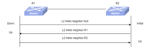
The neighbor establishment on the broadcast link adopts a three-time handshake mechanism. The following figure shows the process of IS-IS neighbor state changes on the broadcast link.
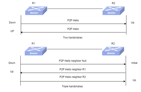
There are two handshake mechanisms and three handshake mechanisms for establishing neighbors on a point-to-point chain:
- Two handshakes: If a Hello message is received from the other end, the neighbor status will be Up.
- Triple handshake: Both neighbors send P2P Hello messages three times to establish a neighbor relationship, similar to the process of establishing neighbors on a broadcast link.
IS-IS authentication method
Section titled “IS-IS authentication method”There are three authentication methods for IS-IS: interface authentication, area authentication, and routing domain authentication. These three authentication methods can all choose to use plaintext authentication and MD5 authentication. Clear text authentication directly adds the configured password to the message, which will be determined by the network detector, so it is not secure. MD5 authentication applies the MD5 algorithm to the configured password before adding it to the message, which enhances the security of the password.
Table 3 IS-IS authentication method
| Authentication method | Description |
|---|---|
| Interface authentication | Encapsulate authentication information in IS-IS Hello messages, only authenticated messages will be received by neighboring routing devices, and neighbor relationships can be established. |
| Area authentication | Encapsulate the authentication password in IS-IS CSNP, PSNP, and LSP messages in Level-1 area, and only authenticated messages will be received. |
| Route domain authentication | Encapsulate the authentication password in IS-IS CSNP, PSNP, and LSP messages in Level-2 area, and only authenticated messages will be received. |
IS-IS route cost
Section titled “IS-IS route cost”In the early days of ISO10589, the maximum cost value that could be configured under an interface that enabled the IS-IS protocol was 63, and the IS-IS cost type was considered narrow. However, in large-scale network design, a smaller measurement range cannot meet practical needs. So in RFC3784, it is specified that the interface cost value for enabling the IS-IS protocol can be extended to 16777215, and the IS-IS routing cost value can reach 4261412864. At this point, the cost of IS-IS is wide. There are differences in TLVs that can be configured for different types of expenses. TLVs used for narrow types are:
- 128 TLV (IP Internal Reachability TLV): Used to carry IS-IS routing information within the routing domain.
- 130 TLV (IP External Reachability TLV): Used to carry IS-IS routing information outside the routing domain
- 2 TLV: Used to carry neighbor information TLVs used under wide type:
- 35 TLV (Extended IP Reachability TLV): Used to replace the original IP Reachability TLV, it carries IS-IS routing information, expands the range of routing overhead values, and can carry sub TLVs.
- 22 TLV (IS Extended Neighbors TLV): Used to carry neighbor information. IS-IS under wide type and IS-IS under narrow type cannot achieve interoperability. If interoperability is required, it must be set to a consistent overhead type so that all routers on the network can receive all packets sent by other routers. When configuring the cost type as compatible, a message will be sent separately for narrow and wide types.
ISIS router overload
Section titled “ISIS router overload”IS-IS uses the IS-IS overload flag to identify overload status. The IS-IS overload flag refers to the OL field in the IS-IS LSP message. After setting the overload flag on the device, other devices will not use this device for forwarding during SPF calculation, only calculating the direct route on this device. When the system is unable to save a new LSP for various reasons, resulting in the inability to maintain normal LSDB synchronization, the routing information calculated by the system will be incorrect. In this case, the system can automatically enter an overload state, where the route reached through the device is not calculated, but the direct connection route of the device will not be ignored. n addition to automatic overload caused by device abnormalities, the system can also be manually configured to enter an overload state. When certain IS-IS devices in the network need to be upgraded or maintained, they need to be temporarily isolated from the network. At this point, an overload flag can be set for the device to prevent other devices from forwarding traffic through the node.
IS-IS Configuration
Section titled “IS-IS Configuration”Prerequisite: Configure the interface IP to make the network layer of adjacent nodes reachable.
Table 4 Overview of IS-IS Configuration Tasks
| Configuration Tasks | Description | Refer to | |
|---|---|---|---|
| Is-IS Basic functions | Enable IS-IS | Required | Enable IS-IS |
| Interface enable IS-IS function | Required | Interface enable IS-IS function | |
| Configure IS-IS Level | Optional | Configure IS-IS Level | |
| Configure interface IS-IS Level | Optional | Configure interface IS-IS Level | |
| Configure IS-IS metric type | Optional | Configure IS-IS metric type | |
| Configure IS-IS interface metric | Optional | Configure IS-IS interface metric | |
| Configure IS-IS network type | Optional | Configure IS-IS network type | |
| Configure IS-IS LSP parameters | Optional | Configure IS-IS LSP parameters | |
| Configure IS-IS neighbor detection parameters | Optional | Configure IS-IS neighbor detection parameters | |
| Config IS-IS DIS election priority | Optional | Config IS-IS DIS election priority | |
| Configure IS-IS interface authentication | Optional | Configure IS-IS interface authentication | |
| Configure IS-IS area authentication | Optional | Configure IS-IS area authentication | |
| Configure IS-IS route area authentication | Optional | Configure IS-IS route area authentication | |
| Configure IS-IS default route | Optional | Configure IS-IS default route | |
| Introduce other protocols route | Optional | Introduce other protocols route | |
| Configure IS-IS and BFD linkage | Optional | Configure IS-IS and BFD linkage |
IS-IS Default Setting
Section titled “IS-IS Default Setting”Table 5 ISIS Default Setting
| Parameter | Default value |
|---|---|
| ISIS | Disable |
| DIS priority | 64 |
| Level | Level-1-2 |
| IS-IS Network type | Broadcast |
| IS-IS Cost type | wide |
| IS-IS interface cost | 10 |
| IS-IS time interval | Hello message time interval:3sCNSP message time interval:10sHello message timeout:30sLAS message update interval:900sLSP Maximum survival time:1200s |
Enable IS-IS
Section titled “Enable IS-IS”Table 6 Enable IS-IS
| Purpose | Commands | Description |
|---|---|---|
| Enter global configuration view. | configure terminal | - |
| Configure IS-IS packet trap to CPU | isis enable | Default disable |
| Enter IS-IS configuration view. | router isis area_tag [vrf vrf-name] | - |
| Configure NET | net xx.xxxx…xxxx.xxxx.xxxx.xx | 1) The System ID part in NET uniquely identifies a router in the network. 2) The last two fixed digits of NET under IP network are 00 |
Enable interface IS-IS
Section titled “Enable interface IS-IS”Table 7 Enable interface IS-IS
| Purpose | Commands | Description |
|---|---|---|
| Enter global configuration view. | configure terminal | - |
| Enter interface configuration view. | interface {ethernet interface-name[.subinterface-number] |link-aggregation lag-id[.subinterface-number]|vlan vlan-id} | - |
| Enable interface IS-IS. | ip router isis area_tag | - |
Configure IS-IS Level
Section titled “Configure IS-IS Level”Table 8 Configure IS-IS level
| Purpose | Commands | Description |
|---|---|---|
| Enter global configuration view. | configure terminal | - |
| Enter IS-IS configuration view. | router isis area_tag [vrf vrf-name] | - |
| Configure IS-IS level | is-type {level-1|level-1-2|level-2-only} | The default level is level-2 |
Configure interface IS-IS level
Section titled “Configure interface IS-IS level”Table 9 Configure interface IS-IS level
| Purpose | Commands | Description |
|---|---|---|
| Enter global configuration view. | configure terminal | - |
| Enter interface configuration view. | interface {ethernet interface-name[.subinterface-number] |link-aggregation lag-id[.subinterface-number]|vlan vlan-id} | - |
| Configure interface IS-IS level | isis circuit-type {level-1|level-1-2|level-2-only} | - |
Configure IS-IS metric type
Section titled “Configure IS-IS metric type”Table 10 Configure IS-IS metric type
| Purpose | Commands | Description |
|---|---|---|
| Enter global configuration view. | configure terminal | - |
| Enter IS-IS configuration view. | router isis area_tag [vrf vrf-name] | - |
| Configure IS-IS metric style | metric-style {narrow|transition|wide} | - |
Configure interface IS-IS metric
Section titled “Configure interface IS-IS metric”Table 11 Configure interface IS-IS metric
| Purpose | Commands | Description |
|---|---|---|
| Enter global configuration view. | configure terminal | - |
| Enter interface configuration view. | interface {ethernet interface-name[.subinterface-number] |link-aggregation lag-id[.subinterface-number]|vlan vlan-id} | - |
| Configure interface IS-IS metric | isis metric [level-1|level-2] metric_value | The value of metric_value is related to the IS-IS overhead type. When the cost type is narrow, the cost value range is [0,63]. When the cost type is wide, the cost value range is [0, 16777215] |
Configure IS-IS network type
Section titled “Configure IS-IS network type”Table 12 Configure IS-IS network type
| Purpose | Commands | Description |
|---|---|---|
| Enter global configuration view. | configure terminal | - |
| Enter interface configuration view. | interface {ethernet interface-name[.subinterface-number] |link-aggregation lag-id[.subinterface-number]|vlan vlan-id} | - |
| Configure IS-IS network type | isis network point-to-point | The default network type is broadcast |
Configure IS-IS LSP parameters
Section titled “Configure IS-IS LSP parameters”Table 13 Configure IS-IS LSP parameters
| Purpose | Commands | Description |
|---|---|---|
| Enter global configuration view. | configure terminal | - |
| Enter IS-IS configuration view. | router isis area_tag [vrf vrf-name] | - |
| Configure the minimum interval for IS-IS to generate LSP messages | lsp-gen-interval [level-1|level-2] seconds | The value range of seconds is [1,120] |
| Configure the maximum length of LSP messages generated by IS-IS | lsp-mtu mtu | The value range of mtu is [128,4352] |
| Configure LSP maximum survival time | max-lsp-lifetime [level-1|level-2] seconds | The value range of seconds is [350,65235] |
| Configure LSP refresh time | lsp-refresh-interval [level-1|level-2] seconds | The value range of seconds is [1,65235] |
| Configure the minimum calculation interval for SPF | spf-interval [level-1|level-2] seconds | The value range of seconds is [128,4352] |
Configure IS-IS neighbor detection parameters
Section titled “Configure IS-IS neighbor detection parameters”Table 14 Configure IS-IS neighbor detection parameters
| Purpose | Commands | Description |
|---|---|---|
| Enter global configuration view. | configure terminal | - |
| Enter interface configuration view. | interface {ethernet interface-name[.subinterface-number] |link-aggregation lag-id[.subinterface-number]|vlan vlan-id} | - |
| Configure IS-IS hello message interval | isis hello-interval [level-1|level-2] seconds | The value range of seconds is [1,600] |
| Configure IS-IS hello detection multiplier | isis hello-multiplier [level-1|level-2] times | The value range of time is [2,100] |
Configure IS-IS DIS election priority
Section titled “Configure IS-IS DIS election priority”Table 15 Configure IS-IS DIS election priority
| Purpose | Commands | Description |
|---|---|---|
| Enter global configuration view. | configure terminal | - |
| Enter interface configuration view. | interface {ethernet interface-name[.subinterface-number] |link-aggregation lag-id[.subinterface-number]|vlan vlan-id} | - |
| Configure IS-IS DIS election priority | isis priority priority | The value range of priority is [0,127] |
Configure IS-IS interface authentication
Section titled “Configure IS-IS interface authentication”Table 16 Configure IS-IS interface authentication
| Purpose | Commands | Description |
|---|---|---|
| Enter global configuration view. | configure terminal | - |
| Enter interface configuration view. | interface {ethernet interface-name[.subinterface-number] |link-aggregation lag-id[.subinterface-number]|vlan vlan-id} | - |
| Configure IS-IS interface authentication | isis password {clear|md5} password | - |
Configure IS-IS area authentication
Section titled “Configure IS-IS area authentication”Table 17 Configure IS-IS area authentication
| Purpose | Commands | Description |
|---|---|---|
| Enter global configuration view. | configure terminal | - |
| Enter IS-IS configuration view. | router isis area_tag [vrf vrf-name] | - |
| Configure IS-IS area authentication | area-password {clear|md5} password [authenticate snp {send-only|validate}] | - |
Configure IS-IS route area authentication
Section titled “Configure IS-IS route area authentication”Table 18 Configure IS-IS route area authentication
| Purpose | Commands | Description |
|---|---|---|
| Enter global configuration view. | configure terminal | - |
| Enter IS-IS configuration view. | router isis area_tag [vrf vrf-name] | - |
| Configure IS-IS route area authentication | domain-password {clear|md5} password [authenticate snp {send-only|validate}] | - |
Configure IS-IS default route
Section titled “Configure IS-IS default route”Table 19 Configure IS-IS default route
| Purpose | Commands | Description |
|---|---|---|
| Enter global configuration view. | configure terminal | - |
| Enter IS-IS configuration view. | router isis area_tag [vrf vrf-name] | - |
| Configure IS-IS default route | default-information originate {ipv4|ipv6} {level-1|level-2} always [ metric metric_value] [ route-map route-map-name] | - |
Introduce other protocols route
Section titled “Introduce other protocols route”Table 20 Introduce other protocols route
| Purpose | Commands | Description |
|---|---|---|
| Enter global configuration view. | configure terminal | - |
| Enter IS-IS configuration view. | router isis area_tag [vrf vrf-name] | - |
| Introduce other protocols route | redistribute {ipv4|ipv6} {ospf|kernel|connected|static|rip|bgp} {level-1|level-2} [metric metric_value] [route-map route-map-name]** | - |
Configure IS-IS and BFD linkage
Section titled “Configure IS-IS and BFD linkage”Table 21 Configure IS-IS and BFD linkage
| Purpose | Commands | Description |
|---|---|---|
| Enter global configuration view. | configure terminal | - |
| Enter interface configuration view. | interface {ethernet interface-name[.subinterface-number] |link-aggregation lag-id[.subinterface-number]|vlan vlan-id} | - |
| Configure IS-IS and BFD linkage | isis bfd | - |
| Configure the profile for binding BFD | isis bfd profile profile-name | Bind user-defined BFD profile to modify BFD session parameters. The default BFD parameter is 3 × 300ms |
Display and Maintenance
Section titled “Display and Maintenance”able 22 IS-IS Display and Maintenance
| Purpose | Command | Description |
|---|---|---|
| Show IS-IS neighbor information. | show isis [vrf vrf-name] neighbor [OPTIONS] | The options for OPTION are as follows:detail : displays detailed neighbor information.SystemID : displays information about the neighbors of the specified System ID |
| Show interface IS-IS information. | show isis [vrf vrf-name] interface [OPTIONS] | The options for OPTION are as follows:detail : displays detailed interface information |
| Show IS-IS route information | show isis route [OPTIONS] | The options for OPTION are as follows:The level-1 : displays the routing information of level-1 neighbors.The level-2 : displays routing information for level-2 neighbors |
| Show IS-IS link status information | show isis database [OPTIONS] | The options for OPTION are as follows:detail : displays detailed information about the link status |
Typical Configuration Guide
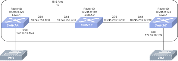
Section titled “Typical Configuration Guide”- Networking Requirements Hosts from different network segments are connected through three switches, all of which run the IS-IS protocol. Request to configure IS-IS neighbors so that VM1 attached to Switch A can communicate with VM2 attached to Switch C.
- Topology
- Configuration steps
- Check that the link status of the ports used by the switch is normal, and all ports remain stable in UP state.
- Configure the interface IP and Loopback0 IP of the switch.
- Configure the IS-IS Level and NET of the switch.
- Configure IS-IS interface authentication mode and authentication key.
- Introducing direct routing in the IS-IS protocol of Switch A and C.
Switch A
interface loopback 0 ip address 10.245.0.129/32 exit!interface ethernet 0/80 ip address 10.245.253.1/30 exit!interface ethernet 0/88 ip address 172.16.10.1/24 exit!isis enable!router isis 1 is-type level-1 net 10.0000.0102.4500.0129.00 redistribute ipv4 connected level-1 exit!interface ethernet 0/80 ip router isis 1 isis password md5 12345678Switch B
!interface loopback 0 ip address 10.245.0.169/32 exit!interface ethernet 0/64 ip address 10.245.253.2/30 exit!interface ethernet 0/76 ip address 10.245.253.122/30 exit!isis enable!router isis 1 net 10.0000.0102.4500.0169.00 exit!interface ethernet 0/64 ip router isis 1 isis password md5 12345678 exit!interface ethernet 0/76 ip router isis 1 isis password md5 12345678 exitSwitch C
interface loopback 0 ip address 10.245.0.174/32 exit!interface ethernet 0/64 ip address 10.245.253.121/30 exit!interface ethernet 0/88 ip address 172.16.20.1/24 exit!isis enable!router isis 1 is-type level-1 net 10.0000.0102.4500.0174.00 redistribute ipv4 connected level-1exit!interface ethernet 0/64 ip router isis 1 isis password md5 12345678 exit- Verify the configuration
#Check if the IS-IS neighbor relationship has been successfully established
Switch A
SwitchA# show isis neighbor detailArea 1: SwitchB Interface: ethernet 0/80, Level: 1, State: Up, Expires in 28s Adjacency flaps: 1, Last: 1h23m34s ago Circuit type: L1L2, Speaks: IPv4 SNPA: 60eb.5a01.30db, LAN id: 0102.4500.0169.14 LAN Priority: 64, is DIS, DIS flaps: 1, Last: 1h23m34s ago Area Address(es): 10.0000 IPv4 Address(es): 10.245.253.2Switch B
SwitchB # show isis neighbor detailArea 1: SwitchC Interface: ethernet 0/76, Level: 1, State: Up, Expires in 28s Adjacency flaps: 1, Last: 6m54s ago Circuit type: L1, Speaks: IPv4 SNPA: 0001.0203.0405, LAN id: 0102.4500.0169.0d LAN Priority: 64, is not DIS, DIS flaps: 1, Last: 6m54s ago Area Address(es): 10.0000 IPv4 Address(es): 10.245.253.121 SwitchA Interface: ethernet 0/64, Level: 1, State: Up, Expires in 30s Adjacency flaps: 1, Last: 1h24m27s ago Circuit type: L1, Speaks: IPv4 SNPA: 60eb.5a01.1523, LAN id: 0102.4500.0169.14 LAN Priority: 64, is not DIS, DIS flaps: 1, Last: 1h24m27s ago Area Address(es): 10.0000 IPv4 Address(es): 10.245.253.1Switch C
SwitchC# show isis neighbor detailArea 1: SwitchB Interface: ethernet 0/64, Level: 1, State: Up, Expires in 29s Adjacency flaps: 1, Last: 4m7s ago Circuit type: L1L2, Speaks: IPv4 SNPA: 60eb.5a01.30db, LAN id: AI-169.0d LAN Priority: 64, is DIS, DIS flaps: 1, Last: 4m7s ago Area Address(es): 10.0000 IPv4 Address(es): 10.245.253.122#Check for successful IS-IS routing exchange
Switch A
SwitchA# show ip route isisCodes: K - kernel route, C - connected, S - static, R - RIP, O - OSPF, I - IS-IS, B - BGP, E - EIGRP, N - NHRP, T - Table, v - VNC, V - VNC-Direct, A - Babel, F - PBR, f - OpenFabric, > - selected route, \* - FIB route, q - queued, r - rejected, b - backup t - trapped, o - offload failureI>* 1.1.1.141/32 [115/20] via 10.245.253.2, ethernet 0/80, weight 1, 00:05:24I>* 10.245.0.174/32 [115/20] via 10.245.253.2, ethernet 0/80, weight 1, 00:05:24I 10.245.253.0/30 [115/20] via 10.245.253.2, ethernet 0/80 inactive, weight 1, 00:05:47I>* 10.245.253.120/30 [115/20] via 10.245.253.2, ethernet 0/80, weight 1, 00:05:47I>* 10.245.253.124/30 [115/20] via 10.245.253.2, ethernet 0/80, weight 1, 00:05:24I>* 10.245.253.128/30 [115/20] via 10.245.253.2, ethernet 0/80, weight 1, 00:05:24I>* 10.245.253.132/30 [115/20] via 10.245.253.2, ethernet 0/80, weight 1, 00:05:24I>* 10.245.253.136/30 [115/20] via 10.245.253.2, ethernet 0/80, weight 1, 00:05:24I>* 10.250.0.0/24 [115/20] via 10.245.253.2, ethernet 0/80, weight 1, 00:05:24I>* 172.0.0.4/30 [115/20] via 10.245.253.2, ethernet 0/80, weight 1, 00:05:24I>* 172.16.20.0/24 [115/20] via 10.245.253.2, ethernet 0/80, weight 1, 00:05:24Switch B
SwitchC# show ip route isisCodes: K - kernel route, C - connected, S - static, R - RIP, O - OSPF, I - IS-IS, B - BGP, E - EIGRP, N - NHRP, T - Table, v - VNC, V - VNC-Direct, A - Babel, F - PBR, f - OpenFabric, > - selected route, \* - FIB route, q - queued, r - rejected, b - backup t - trapped, o - offload failureI>* 1.1.1.129/32 [115/20] via 10.245.253.122, ethernet 0/64, weight 1, 00:05:58I>* 10.245.0.129/32 [115/20] via 10.245.253.122, ethernet 0/64, weight 1, 00:05:58I>* 10.245.253.0/30 [115/20] via 10.245.253.122, ethernet 0/64, weight 1, 00:05:58I>* 10.245.253.4/30 [115/20] via 10.245.253.122, ethernet 0/64, weight 1, 00:05:58I>* 10.245.253.8/30 [115/20] via 10.245.253.122, ethernet 0/64, weight 1, 00:05:58I>* 10.245.253.12/30 [115/20] via 10.245.253.122, ethernet 0/64, weight 1, 00:05:58I>* 10.245.253.16/30 [115/20] via 10.245.253.122, ethernet 0/64, weight 1, 00:05:58I 10.245.253.120/30 [115/20] via 10.245.253.122, ethernet 0/64 inactive, weight 1, 00:05:58I>* 172.0.0.0/30 [115/20] via 10.245.253.122, ethernet 0/64, weight 1, 00:05:58I>* 172.16.10.0/24 [115/20] via 10.245.253.122, ethernet 0/64, weight 1, 00:05:58172.16.10.0/24 is the direct connection network segment of Switch A, and 172.16.20.0/24 is the direct connection network segment of Switch C. This indicates that both Switch A and Switch C have obtained each other’s direct connection route through IS-IS.
#Use the ping command to verify connectivity
VM1# ping 172.16.20.2 src 172.16.10.2PING 172.16.20.2 (172.16.20.2) from 172.16.10.2 : 56(84) bytes of data.64 bytes from 172.16.20.2: icmp_seq=1 ttl=64 time=0.580 ms64 bytes from 172.16.20.2: icmp_seq=2 ttl=64 time=32.3 ms64 bytes from 172.16.20.2: icmp_seq=3 ttl=64 time=0.374 ms64 bytes from 172.16.20.2: icmp_seq=4 ttl=64 time=2.68 ms64 bytes from 172.16.20.2: icmp_seq=5 ttl=64 time=15.0 ms--- 172.16.20.2 ping statistics ---5 packets transmitted, 5 received, 0% packet loss, time 4032msrtt min/avg/max/mdev = 0.374/10.174/32.259/12.289 msVM1 and VM2 can ping each other.