
Network Management Configuration Guide
此内容尚不支持你的语言。
Introduction
Section titled “Introduction”LLDP (Link Layer Discovery Protocol) is a Layer 2 discovery protocol defined in IEEE 802.1ab. In simple terms, LLDP is a proximity discovery protocol, a means of transmitting information between two directly connected devices. For example, details such as device configuration and device identification can be advertised using this protocol.
Basic Concepts
Section titled “Basic Concepts”LLDP Packet
The LLDP packet structure is shown in the figure below.
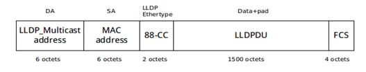
- DA: Destination MAC, which is a multicast address whose value corresponds to the meaning shown in the table below.
- SA: Source MAC, generally using the system MAC.
- LLDP Ethertype: The frame type, by this byte, the switch can determine that it is an LLDP frame and then hand it over to the LLDP module for processing, the value is 0x88CC.
- LLDPDU: LLDP Data Unit, which is the main body of LLDP information exchange.
- FCS: Frame check bit.
Table 1 Destination MAC Address Table
| Destination MAC | Meaning | Description |
|---|---|---|
| 01:80:c2:00:00:0e | Nearest bridge | LLDP packets of the nearest bridge bridge type, where the packet is restricted to the local network and cannot be forwarded by any bridge or route device |
| 01:80:c2:00:00:03 | Nearest non-TPMR bridge | Nearest non-TPMR bridg LLDP packets, packets are only forwarded by Two-Port MAC Relay (TPMR), no other bridge or route device on the bridge forwards the packet |
| 01:80:c2:00:00:00 | Nearest Customer Bridge | LLDP packets of the nearest customer bridge type, packets are only propagated between two Customer Bridges |
LLDPDU Structure
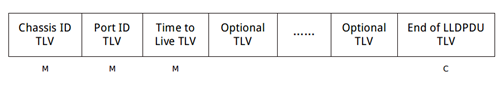
The LLDPDU is the body of the LLDP information exchange and determines which layer 2 information about the switch can be discovered through the LLDP protocol. the LLDPDU structure is shown in the figure below.
The basic information unit in the LLDPDU is the TLV
- T-TYPE: the type of information.
- L-LENGTH: the length of the packet.
- V-VALUE: the value of the packet, i.e. what is actually to be transmitted.
TLV Type
During the LLDP frame interaction, the LLDPDU often contains a number of different TLVs depending on the requirements, according to which it transmits or receives information about itself and neighboring devices. The LLDPDU is fixed starting with Chassis ID TLV, Port ID TLV and Time to Live TLV, and ends with End of LLDPDU TLV, these four TLVs are mandatory TLVs. other are optional TLVs, which can be defined by the switch whether to include in the LLDPDU or not.
Basic TLV Types
Table 2 Basic TLV Types
| TLV type | Description | Mandatory |
|---|---|---|
| Chassis Id | Port MAC address of the sending device | Yes |
| Port Id | Used to identify the port on the sender side of the LLDPDU | Yes |
| Time to Live | Duration of information on this device on neighboring devices | Yes |
| System Name | Name of the switch | No |
| System Description | System description of the switch | No |
| System Capabilities | The main functions of the system and which main functions are enabled | No |
| Management Address | The management address, and the corresponding interface number and OID (Object Identifier). The content of the management address is the IP address specified by the user; if the user has not configured it, the management address is the primary IP address of the VLAN through which the interface is allowed and with the smallest VLAN ID value; if the VLAN with the smallest VLAN ID value is not configured with a primary IP address, the management address value is 127.0.0.1 | No |
| Port Description | Description string of the Ethernet port | No |
| End of LLDPDU | Marking the end of LLDPDU | Yes |
Organization Specific TLV
- TLV as defined by IEEE 802.1
The TLV defined by IEEE802.1 is mainly used to describe things like information about VLAN and ports that send LLDP packets.
Table 3 TLV Types as Defined by IEEE 802.1
| TLV type | Description | Subtype | Does it support |
|---|---|---|---|
| Port VLAN TLV | The value of the default VLAN of the port on which the LLDP packet was sent | 01 | Support |
| Port and protocal VLAN TLV | The value of the VLAN defined by the port | 02 | Support |
| VLAN Name TLV | Name of the VLAN where the port is located | 03 | Support |
| Protocol identity TLV | Types of protocols supported by the port | 04 | Support |
- TLV as Defined by IEEE 802.3
TLV as defined by IEEE802.3 is mainly used for negotiation of port performance, etc.
Table 4 TLV Types as Defined by IEEE 802.3
| TLV type | Description | Subtype | Support |
|---|---|---|---|
| MAC/PHY Configuration/Status TLV | The speed and duplex status of the port, whether the port speed auto-negotiation is supported, whether auto-negotiation is enabled, and the current speed and duplex status | 01 | YES |
| Power Via MDI TLV | Power capability of the port, e.g. whether it supports PoE, whether it is a supply or a receiving device | 02 | YES |
| Link Aggregation TLV (deprecated) | Whether the port supports link aggregation and whether link aggregation is enabled | 03 | YES |
| Maximum Frame Size TLV | The maximum frame length supported by the port, taken as the port’s Maximum Transmission Unit (MTU) | 04 | YES |
- LLDP-MED TLV
LLDP-MED TLVs are used in the field of VoIP (Voice over Internet Protocol). This type of TLV can be used to exchange basic configuration, address, network policy and management information of voice devices, among other things, to enable the interoperability of voice devices from different manufacturers.
Table 5 Media Endpoint Discovery (MED) Related TLVs
| TLV type | Description | Subtype | Support |
|---|---|---|---|
| LLDP-MED Capabilities TLV | The type of the current device and the LLDP-MED TLV type that can be encapsulated in the LLDPDU | 1 | YES |
| Network Policy TLV | VLAN ID, Layer 2 priority and DSCP value for Voice VLAN | 2 | YES |
| Location Identification TLV | Location identification information for use by other devices in location-based applications | 3 | YES |
| Extended Power-via-MDI TLV | Provides information on the extended power supply capacity of the current equipment | 4 | YES |
| Inventory TLV | Manufacturers of device | 5 to 11 | NO |
LLDP Default Configuration
Section titled “LLDP Default Configuration”The default configuration of LLDP is shown in the table below.
Table 6 LLDP Default Configuration
| Parameters | Default value |
|---|---|
| LLDP function | Enable |
| LLDP operating mode | rx-and-tx |
| LLDP packet sending interval | 30 seconds |
| LLDP aging time | 120 seconds |
| LLDP advertises the management IP address | Enable |
| LLDP capabilities | Enable |
Disable LLDP
Section titled “Disable LLDP”Table 7 Disable LLDP
| Purpose | Commands | Description |
|---|---|---|
| Enter global configuration view | configure terminal | - |
| Disable LLDP | lldp disable | - |
LLDP Configuration
Section titled “LLDP Configuration”Table 8 LLDP Configuration
| Purpose | Commands | Description |
|---|---|---|
| Enter global configuration view | configure terminal | - |
| Configure subtype in LLDP messages | lldp port-id-subtype{local|ifname|macaddress} | - |
| Configure the time interval for sending LLDP messages. | lldp message-transmission interval interval-time | interval-time: time interval, range 1-3600 |
| Configure the hold-time of LLDP. | lldp message-transmission hold hold-time | hold-time: time parameter, range 1-100.TTL of LLDP message = Min(65535,(interval * hold)) |
| Disable LLDP to declare the mac address of the management port. | no lldp management-address-advertisements enable | - |
| Disable LLDP capabilities declaration | no lldp capabilities-advertisements enable | - |
Display and Maintenance
Section titled “Display and Maintenance”Table 9 LLDP Display and Maintenance
| Purpose | Commands | Description |
|---|---|---|
| Show LLDP neighbors | show lldp neighbor {summary|interface interface_name} | Specify the interface to view neighbor details. |
| Show LLDP configuration | show lldp local{summary|interface interface_name} | Specify the interface to view local details. |
Typical Configuration Example
Section titled “Typical Configuration Example”#Check LLDP neighbor table.
sonic# show lldp neighbor summaryCapability codes: (R) Router, (B) Bridge, (O) OtherLocalPort RemoteDevice RemotePortID Capability RemotePortDescr----------- -------------- -------------- ------------ -----------------0/48 spine-228 C1 BR Ethernet00/60 sonic-227 C6 BR Ethernet680/72 sonic-102 C7 BR 0/72--------------------------------------------------Total entries displayed: 3#Check LLDP neighbor details for device 0/48 interface.
sonic# show lldp neighbor interface 0/48-------------------------------------------------------------------------------LLDP neighbors:-------------------------------------------------------------------------------Interface: 0/48 , via: LLDP, RID: 1, Time: 1 day, 07:13:23 Chassis: ChassisID: mac 18:17:25:37:65:40 SysName: spine-228 SysDescr: Debian GNU/Linux 9 (stretch) Linux 4.9.0-14-2-amd64 #1 SMP Debian 4.9.246-2 (2020-12-17) x86_64 MgmtIP: 10.250.0.228 MgmtIface: 2 Capability: Bridge, on Capability: Router, on Capability: Wlan, off Capability: Station, off Port: PortID: local C1 PortDescr: 0/0 TTL: 120-------------------------------------------------------------------------------Introduction
Section titled “Introduction”SNMP (Simple Network Management Protocol) is a standard protocol for network management widely used in TCP/IP networks. SNMP provides a method of managing devices through a central computer (i.e. network management workstation) running network management software.SNMP has the following features.
- Simplicity: SNMP uses a polling mechanism to provide the most basic set of features for small, fast, low-cost environments and is supported by most devices as SNMP is carried by UDP packets.
- Robust: The goal of SNMP is to ensure that management information is delivered at any two points so that administrators can retrieve information at any node on the network for troubleshooting SNMP is currently available in three versions: v1, v2c and v3. v1 is basically the same as v2, v2c can be seen as an enhanced version of v1 with some new operations, while v3 has undergone major changes to provide authentication and encryption security mechanisms, as well as user- and view- based access control features for enhanced security.
Basic Concepts
Section titled “Basic Concepts”SNMP Management Model
Section titled “SNMP Management Model”SNMP is an application layer protocol specifically designed for network management. There are two roles in the SNMP protocol, one is the network management system and the other is the network device being managed. The SNMP system consists of NMS (Network Management System), Agent, Management object and MIB (Management Information Base). The NMS acts as the network management center for the entire network and manages the switches. Each managed device contains Agent, MIB and multiple management objects residing on the switch. The NMS interacts with the Agent running on the managed device and the Agent completes the NMS commands by manipulating the MIB on the switch. The SNMP management model is shown in figure below and the main elements of the model are as follows.
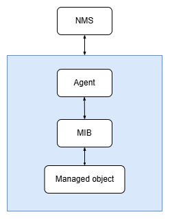
- The NMS plays the role of a manager in the network and is a system that uses the SNMP protocol to manage/monitor network devices, running on NMS server, which can send requests to the Agent on the switch to query or modify the values of one or more specific parameters. The NMS can receive active Trap packets from the Agent on the switch in order to be informed of the current status of the managed device.
- The Agent is an agent process in the managed device that maintains information and data about the managed devices and responds to requests from the NMS, reporting management data to the NMS that sent the request. The Agent receives the request information from the NMS, completes the corresponding instructions through the MIB table, and then responds to the NMS with the operation results. In the event of a fault or other event, the switch will send a proactive message to the NMS via the Agent, reporting the current status change of the switch to the NMS.
- Management object refers to a managed object. Each device may contain multiple managed objects, which may be a piece of hardware in the switch or a collection of parameters configured on hardware, software (e.g. routing protocols).
- The MIB is a database that specifies the variables maintained by the management object (i.e. information that can be queried and set by the Agent.) The MIB defines a series of properties of the management object in the database: the name of the object, the state of the object, the access rights of the object and the data type of the object, etc. By querying the MIB, the Agent can get information about the current state of the switch.
SNMP Packet Structure
Section titled “SNMP Packet Structure”SNMPv1 and SNMPv2c packets consist mainly of version, community name, and SNMP PDU. The packets for each type of SNMP operation are encapsulated in SNMP PDU. As shown in figure below.
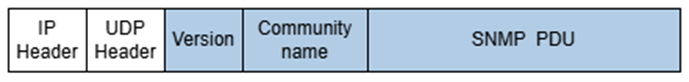
- Version: Indicates the version of SNMP, the corresponding field value is 0 if it is SNMPv1 packet and 1 for SNMPv2c.
- Community name: Used to complete authentication between SNMP Agent and NMS, in the form of string, user can define. The community name includes “read” and “write”, when performing SNMP query operation, the “read” community name is used for authentication; when performing SNMP setup operation, the “write” community name is used for authentication. SNMPv3 packets mainly consist of Version, MsgID, MaxSize, Flags, Security Model, Security Parameters, Context EngineID, Context Name and SNMP PDU, as shown in figure below. The SNMP PDU format of SNMPv3 packets is the same as that of SNMPv2c. SNMPv3 packets can use the authentication mechanism, which encrypts the Context EngineID, Context Name and SNMP PDUs.

- Version: Indicates the version of SNMP, if it is an SNMPv3 packet then the corresponding field value is 3.
- MsgID: The sequence number of the request packet.
- MaxSize: The maximum number of bytes that the packet sender can hold and receive.
- Flags: Packet identification bits, occupying one byte, with three characteristic bits: reportableFlag, privFlag and authFlag.
- reportableFlag=1, the SNMPv3 packet recipient must send a Report PDU to the sender if it can generate Report PDU; reportableFlag=0, the SNMPv3 packet recipient does not send a Report PDU. Report is only used when the SNMP PDU cannot be decrypted (e.g. decryption failure due to key error, etc.).
- privFlag=1, to encrypt SNMPv3 packets; privFlag=0, not to encrypt SNMPv3 packets.
- authFlag=1 for authentication of SNMPv3 packets; authFlag=0 for no authentication of SNMPv3 packets.
- Any combination is possible except for the case where privFlag=1 and authFlag=0. So when configuring the security level of SNMPv3, it is important to note that if the user group is at the privacy level, the user and alert host must be at the privacy level; if the user group is at the authentication level, the user and alert host can be privacy or authentication level.
- SecurityModel: The security model used for the packet, both the sender and the receiver must use the same security model.
- SecurityParameters: Including information about the SNMP entity engine, username, authentication parameters, encryption parameters and other security information.
- Context EngineID: SNMP unique identifier which together with the PDU type, determines which application it should be sent to.
- Context Name: Identifies the collection of management information that is accessible by an SNMP entity.
Working Principle
Section titled “Working Principle”SNMPv1 and SNMPv2c work in the same way. SNMPv3 is implemented in the same way as SNMPv1/SNMPv2c, with the only difference being that SNMPv3 adds authentication and encryption processing.
SNMP Query
SNMP query means that the NMS sends a query request to the SNMP Agent on its own initiative. SNMP Agent receives the query request, completes the corresponding command through the MIB table and returns the result to the NMS. The SNMP query process is basically the same for all versions, the only difference is that SNMPv3 has added authentication and encryption processing. There are three SNMP query operations: Get, GetNext and GetBulk. SNMPv1 version does not support the GetBulk operation.
- Get: The NMS uses this operation to obtain one or more parameter values from the SNMP Agent.
- GetNext: The NMS uses this operation to get the next parameter value from the SNMP Agent for one or more parameters.
- GetBulk: Based on the GetNext implementation, this is equivalent to performing multiple GetNext operations in succession. The number of times the managed device performs GetNext during a single GetBulk packet interaction can be set on the NMS.
SNMP Set
SNMP set means that the NMS actively sends a request to the SNMP Agent to perform Set operation on the switch. After receiving the Set request, the SNMP Agent completes the corresponding command through the MIB table and sends the result back to the NMS. The SNMP set operation has only one Set, which is used by the NMS to set the value of one or more parameters in the SNMP Agent. Similar to the query operation, the SNMPv3 version adds authentication and encryption processing, and the rest of the work process does not differ between versions.
SNMP Response
SNMP response means that the SNMP Agent receives the request from the NMS and then completes the corresponding query/modification operation through the MIB and then sends the information back to the NMS. The SNMP response has only one Response operation, which can return one or more parameter values. This operation is issued by the Agent and is the response operation to the four operations GetRequest, GetNextRequest, SetRequest and GetBulkRequest.
SNMP Traps
SNMP Traps are alarms or events generated by the SNMP Agent that are actively reported to the NMS by the SNMP Agent so that the network administrator is kept informed of the current operating status of the switch. There are two ways for SNMP Agent of SNMP Traps: Trap and Inform. Inform is not supported in SNMPv1. The difference between Trap and Inform is that after the SNMP Agent sends an alert or event to the NMS via Inform, the NMS needs to reply Inform Response for acknowledgement.
SNMP Configuration
Section titled “SNMP Configuration”Table 10 Overview of SNMP Configuration Tasks
| Configuration Tasks | Description |
|---|---|
| Configure SNMP Community | Optional |
| Configure SNMP User | Optional |
| Configure SNMP Agent Trap | Optional |
| Configure SNMP Agent Source | Optional |
Configure SNMP Community
Section titled “Configure SNMP Community”Table 11 Configure the SNMP Community
| Purpose | Commands | Description |
|---|---|---|
| Enter global configuration view. | configure terminal | - |
| Add SNMP community. | snmp-agent community name | - |
Configure SNMP User
Section titled “Configure SNMP User”Table 12 Configure the SNMP User
| Purpose | Commands | Description |
|---|---|---|
| Enter global configuration view. | configure terminal | - |
| Add SNMP user. | snmp-agent user name [authentication-mode authen-protocol authKey [privacy-mode privacy-protocol privKey ]] | authen-protocol: authentication method with md5 or shaauthKey: authentication passwordprivacy-protocol: encryption method des or aesprivKey : Encrypted password |
Configure SNMP Agent Trap
Section titled “Configure SNMP Agent Trap”Table 13 Configure the SNMP Agent Trap
| Purpose | Commands | Description |
|---|---|---|
| Enter global configuration view. | configure terminal | - |
| Add SNMP agent trap. | snmp-agent trap-target {v1|v2c|v3} A.B.C.D [udp-port portnum] [vrf vrfname] [community *community_name *|user user_name] | A.B.C.D: IP address of the destination of the trap.udp-port: default 162, range 0-65535 |
Configure SNMP Agent Source
Section titled “Configure SNMP Agent Source”Table 14 Configure the SNMP Agent Source
| Purpose | Commands | Description |
|---|---|---|
| Enter global configuration view. | configure terminal | - |
| Add SNMP agent source. | snmp-agent source A.B.C.D [udp-port portnum] [vrf vrfname] | A.B.C.D: destination IP address of sourceudp-port: default 162, range 0-65535 |
Display and Maintenance
Section titled “Display and Maintenance”Table 15 SNMP Display and Maintenance
| Purpose | Commands | Description |
|---|---|---|
| Show community configuration. | show snmp-agent community | - |
| Show SNMPv3 users. | show snmp-agent user | - |
| Show trap server configuration. | show snmp-agent trap-target | - |
| Display the configuration of the source address and port of the agent. | show snmp-agent source | - |
Typical Configuration Example
Section titled “Typical Configuration Example”Configure the SNMP Agent Source
#Configure SNMP agent source
sonic# config terminalsonic(config)# snmp-agent source 10.10.10.2 udp-port 165sonic(config)# snmp-agent source 10.20.10.3#Data lookup on other devices (need to ensure source ip is pingable)
root@asterfusion:/# snmpwalk -v 1 -c public 10.10.10.2:165 .1.3.6.1.2.1.25.2.2.0iso.3.6.1.2.1.25.2.2.0 = INTEGER: 8048596root@asterfusion:/# snmpwalk -v 1 -c public 10.20.10.3 .1.3.6.1.2.1.25.2.2.0iso.3.6.1.2.1.25.2.2.0 = INTEGER: 8048596