
MSTP Configuration Guide
此内容尚不支持你的语言。
Introduction
Section titled “Introduction”MSTP (Multiple Spanning Tree Protocol) is a kind of spanning tree protocol developed on the basis of STP/RSTP. Proposed in IEEE802.1s, it inherits all the advantages of STP/RSTP while solving the problem of idle links in STP/RSTP by binding most STP instances to a few VLANs. This means that by forming multiple trees without loops, broadcast storms are resolved and redundant backups are achieved. Multiple spanning trees achieve load balancing between VLANs, with traffic from different VLANs forwarded in different paths.
Basic Concepts
Section titled “Basic Concepts”MSTP Principle
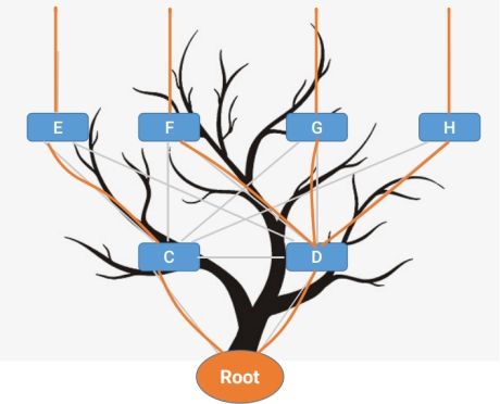
Section titled “MSTP Principle”The principle and calculation method of MSTP is the same as STP/RSTP. The basic idea is to prune the ring network into an acyclic tree by comparing priorities and connecting each sub-priority device in turn from the highest priority root node (Root) in the network.
MSTP Domain
Section titled “MSTP Domain”Unlike STP/RSTP the concept of domain is introduced in MSTP, dividing the whole network into different domains, consisting of multiple switching devices in the switching network and the segments between them. The switches in the same MST domain have the following characteristics.
- Both activated MSTP.
- Has the same domain name.
- Has the same VLAN-to-spanning-tree instance mapping configuration.
- Has the same MSTP revision level configuration.
Multiple MST domains can exist in a LAN, and each MST domain is physically connected to each other directly or indirectly. Users can divide multiple switching devices into the same MST domain by using the MSTP configuration command.
- The configuration resulted in the three domains region 1 to 3 as shown.
- In MSTP instance 0 has a special meaning and is called CISTI (Common and Internal Spanning Tree Instance) and the rest of the spanning trees are called MSTI (Multiple Spanning Tree Instance). By default all VLANs are bound to the CISTI, ensuring the security of the entire network.
- CIST is a single spanning tree that connects all switching devices within a switching network, generated by STP or RSTP protocol calculations. The IST (Internal Spanning Tree) plus the CST (Common Spanning Tree) of all MST domains form a complete spanning tree, or CIST, which is expressed as an IST within a domain, where the switches within the domain are computationally pruned to obtain a spanning tree, and as a CST between domains, where each domain is treated as a single node and a spanning tree is obtained by pruning each domain through calculation.
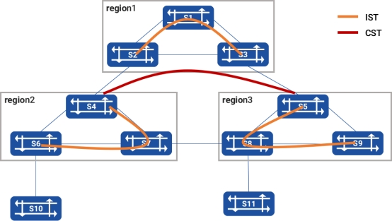
From the figure it can be seen that CIST prunes the ring network into a tree within the domain separately and the entire network is pruned into a loop-free tree in the unit of domain between domains. Due to the introduction of domains and instances, there are two types of root nodes in MSTP: the total root, and the domain root. The total root is a global concept, relative to all interconnected STP/RSTP/MSTP devices with only one total root, and is also the root of the CIST. The domain root is a local concept relative to a specific instance of a specific domain. S1 is the total root and also the domain root of instance0 in region 1.
MSTP Message
Section titled “MSTP Message”MSTP uses the Multiple Spanning Tree Bridge Protocol Data Unit (MST BPDU) as the basis for spanning tree calculations, and MST BPDU messages are used to calculate the spanning tree topology, maintain the network topology and communicate topology change records. The message format is as follows
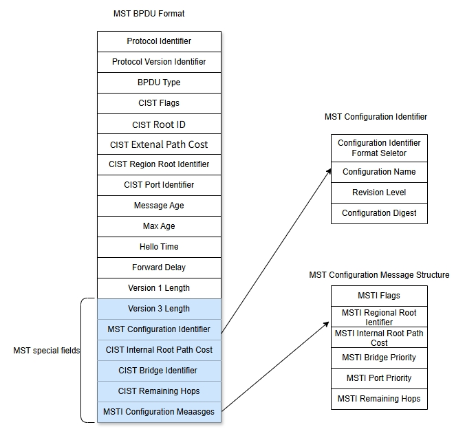
For both intra-domain MST BPDU and inter-domain one, the first 35 bytes are the same as for RST BPDUs. From the 36th byte onwards is the MSTP proprietary field. The final MSTI configuration information field is concatenated by a number of MSTI configuration information groups. The key messages in the MST BPDU are shown in the table below.
Table 1 MST BPDU key messages
| field | Length | Significance |
|---|---|---|
| protocol ID | 2 | 0x00 indicates the STP family of protocols, including STP, RSTP, MSTP |
| Protocol Version ID | 1 | 0x 00 for STP, 0x02 for RSTP, 0x03 for mstp |
| BPDU type | 1 | 0x00 for configure, 0x02 for RSTP or MSTP, 0x80 for TCN |
| flag | 1 | Identification by bit, topology change and P/A bit, role are in it |
| Root ID | 8 | CIST Root ID |
| Extenal Path Cost | 4 | CIST external path cost |
| Regional Root ID | 8 | The root ID in this region |
| Port ID | 2 | Port ID of the sending port |
| Message Age | 2 | Message ageing value |
| Max Age | 2 | Maximum message aging value |
| Hello Time | 2 | Time interval for sending BPDUs |
| Forward delay | 2 | Status switching interval |
| Version1 Length = 0 | 1 | This is the end of RSTP, the next code is MSTP |
| Version3 Length | 1 | Length of Version3 |
| MST Configure ID | 51 | Identifies the MST domain in which it is located |
| CIST Internal Root Path Cost | 4 | CIST internal path cost |
| CIST Bridge ID | 8 | CIST Bridge ID |
| CIST Remaining Hops | 1 | CIST remaining Hops |
| MSTI Configure Message | - | The configuration of the MSTI, describing the individual MSTI instances in turn. This field is not available when there is no MSTI |
The code for the MST Configure ID is as follows.
Table 2 MST Configure ID
| field | Length | Significance |
|---|---|---|
| Configure ID Format Selector | 1 | Use 0x00 directly |
| configure name | 32 | Name |
| revision level | 2 | No specific requirements, for simplicity, use 0 in sonic |
| configure Digest | 16 | The summary information of all MSTI and VLAN mappings on this Bridge |
The code for the MSTI Configure Message is as follows.
Table 3 Message Code
| field | Length | Significance |
|---|---|---|
| MSTI Flags | 1 | Marking by position |
| MSTI Regional Root Identifier | 8 | Domain Root |
| MSTI Internal Root Path Cost | 4 | Intra-domain path cost |
| MSTI Bridge Priority | 1 | Intra-domain Bridge priority |
| MSTI Port Priority | 1 | Intra-domain port priority |
| MSTI Remaining Hops | 1 | MSTI’s remaining hops |
MSTP Topology Calculation Principles
Section titled “MSTP Topology Calculation Principles”MSTP divides the entire network into multiple MST domains, treating each domain as a node. Each MST region is computed based on the STP or RSTP algorithm and generates CST (a single spanning tree). The MSTP vector priority is calculated as follows [Table 42] shown here
Table 4 MSTP Vector Priorities
| Priority vector name | Description |
|---|---|
| Rootbridge ID | The Root Bridge ID is used to select the root bridge in the CIST. The corresponding bridge ID in the BPDU is calculated as: Priority (l6bits) + MAC (48bits) |
| External route path cost (ERPC) | The path cost from the MST domain root to the total root. the external route path cost saved on all switches in the MST domain is the same. If the CIST root bridge is in the domain, the external route path cost saved on all switches in the domain is 0 |
| Domain Root ID | Also commonly referred to as the MSTI tree root, the domain root ID is used to select the root of the tree in MSTI. It is also elected by the bridge ID and is calculated as Priority (l6bits) + MAC (48bits) |
| Internal route path cost (IRPC) | The route path cost for this switch to reach the domain root bridge. The internal route path cost value kept by the domain edge port is greater than (the lower the priority) the internal route path cost kept by the non-domain edge port |
| Designated Bridge | The designated bridge for a CIST or MSTI instance is the nearest upstream switch to the domain root for this switch. If this switch is the master root or domain root, the designated bridge is its own |
| Designated port | The port on the designated bridge that is connected to the root port of this switch is the Designated Port. Its Port ID (Port ID) = Priority (8 bits) + Port Number (8 bits). |
| Receiving ports | The port priority must be an integer multiple of 16 for the port that received the BPDU message. Its Port ID (Port ID) = Priority (8 bits) + Port number (8 bits). Port Priority must be an integer multiple of 16 |
The minimum vector has the highest priority and the rules for comparison are as follows.
First, compare the root bridge IDs. If the root bridge IDs are the same, then compare the ERPC. If the ERPC is still the same, then compare the domain root ID. If the domain root ID is still the same, then compare the IRPC. If the IRPC is still the same, compare the specified bridge ID. If the specified bridge ID is still the same, compare the specified port ID. If the specified port ID is still the same, compare the receiving port ID. Calculation of CIST After configuration message exchange comparison, a switch with the highest priority in the entire network is first selected as the root of the CIST tree, and then the IST is computed within each MST domain by the MSTP protocol algorithm; at the same time MSTP treats each MST domain as a single switch and computes the CST between MST domains by the STP or RSTP protocol algorithm. The CST and IST form the CIST for the entire switch network. Calculation of MSTI Within the MST domain, MSTP generates different spanning tree instances for different VLANs based on the mapping relationship between VLANs and spanning tree instances, with the following characteristics. (1) Each MSTI computes its own spanning tree independently, without interfering with each other. (2) The spanning tree calculation method for each MSTI is essentially the same as for the RSTP. (3) Each MSTI spanning tree can have a different root and a different topology. (4) Each MSTI sends BPDU within its own spanning tree. (5) The topology of each MSTI is determined by command configuration (not automatically generated). (6) The spanning tree parameters can be different for each port on different MSTIs. (7) The role and status of each port can be different on different MSTIs. MSTI Spanning Tree Algorithm Implementation At the beginning, each port of each switch generates a configuration message with its own switch as the root bridge, where the root path cost is 0, the specified bridge ID is its own switch ID and the specified port is this port. Each switch sends its own configuration message out and performs the following operations upon receipt of other configuration messages. (1) When a port receives a configuration message with a lower priority than its own (the comparison of priorities is based on the vector priority comparison rules described earlier), the switch discards the received configuration message and does not do anything with the configuration message for that port. (2) When a port receives a configuration message with a higher priority than the configuration message of this port, the switch replaces the contents of the configuration message of that port with the contents of the received configuration message; then the switch compares the configuration message of that port with the configuration messages of other ports on the switch and selects the best configuration message. The steps to calculate a spanning tree are as follows. (1) Elect the root bridge. This step is performed by comparing the tree root IDs of configuration messages sent by all switches, and the switch with the lowest tree root ID value is the CIST root bridge, or the MST domain root bridge. (2) Elect the root port on a non-root bridge. Each non-root bridge designates the port that receives the optimal configuration message as the root port of its own switch. (3) Election of the designated port. In this step there are two further sub-steps as follows. First, the switch calculates a standard designated port configuration message for each port based on the root port’s configuration message and the root port’s path cost. Replace the tree root ID with the tree root ID in the root port configuration message, replace the root path overhead with the root path overhead in the root port configuration message plus the path overhead of the root port, replace the specified bridge ID with the ID of its own switch, and replace the specified port ID with its own port ID. The switch then compares the configuration message calculated by the above rules with the original configuration message on the corresponding port. If the original configuration message on the port is better, the switch blocks the port and the configuration message on the port remains unchanged, and the port will no longer forward data and will only receive configuration messages (equivalent to the root port); if the configuration message calculated by the above replacement is better than the original configuration message on the port, the switch sets the port as the designated port and the configuration message on the port is replaced with the configuration message calculated by the above replacement and is sent out periodically. (4) After the MSTI spanning tree topology converges, BPDUs are sent periodically according to the Hello timer regardless of whether the non-root bridge receives information from the root bridge. If a port does not receive BPDUs from the specified bridge (the higher-level switch it is connected to) for 3 consecutive Hello times (the default setting), then the switch considers the link with this neighbor has failed.
MSTP’s Handling of Topology Changes
Section titled “MSTP’s Handling of Topology Changes”The criterion for detecting a topology change in MSTP is based on whether the state of non-edge port has migrated to the Forwarding state, and if it has, a topology change occurs. Once the switch detects a topology change, it proceeds as follows.
- Starts a TC While Timer (which is twice the value of Hello Time) for all non-edge designated ports on this switch and clears the incoming MAC addresses for these ports during this time. If it is a state change on the root port, the root port is started.
- These ports where a state change has occurred send out TC BPDUs in which the TC is set until the TC While Timer times out. The root port always has to send such TC BPDUs. The other switches receive the TC BPDUs and perform the following processing.
- Clear all MAC addresses learned by the port, except for ports that receive TC BPDUs.
- Start the TC While timer for all own non-edge assigned ports and root port and repeat the process.
MSTP Configuration
Section titled “MSTP Configuration”The priority of MSTP configuration is: BPDU protection > BPDU filtering > MSTP edge interface (and normal MSTP calculation process).
- If BPDU protection and BPDU filtering are enabled at the same time, BPDU protection takes effect and the interface goes down after receiving the message.
- With BPDU protection or BPDU filtering enabled, the MSTP edge interface will never lose its edge interface role.
MSTP Default Setting
Section titled “MSTP Default Setting”The default setting of MSTP is shown in the table below.
Table 5 MSTP Default Setting
| Parameters | Default value |
|---|---|
| Spanning Tree Protocol working mode | MSTP mode |
| MSTP functionality | The global MSTP function is enabled, and the MSTP function of the port is enabled. |
| Priority of instance | 8 |
| Priority of the port | 128 |
| Calculation of path overhead | dot1t, the IEEE 802.1t standard |
| Forward Delay Time | 15 seconds |
| Hello Time | 2 seconds |
| Max Age Time | 20 seconds |
| Auto edge port | Enabled |
| BPDU filter | Disabled |
| BPDU guard | Disabled |
MSTP Global Switch
Section titled “MSTP Global Switch”Table 6 MSTP Global Switch
| Purpose | Commands | Description |
|---|---|---|
| Enter global configuration view | configure terminal | - |
| Enable global MSTP | mstp state enable | - |
| Disable global MSTP | mstp state disable | - |
Configure MSTP Attributes
Section titled “Configure MSTP Attributes”Table 7 Configure MSTP Attributes
| Purpose | Commands | Description |
|---|---|---|
| Enter global configuration view | configure terminal | - |
| Configure MSTP forward delay | mstp forward_delay time | time: delay time, range 4-30 |
| Configure the MSTP hello packet delivery interval | mstp hello time | time: interval time, range 1-10 |
| Configure MSTP aging time | mstp max_age time | time: ageing time, range 10-1000000 |
| Configure the MSTP domain | mstp name name | - |
| Specify the bridge MAC. | bridge mac HH:HH:HH:HH:HH:HH | - |
Configure MSTP Instance
Section titled “Configure MSTP Instance”Table 8 Configure MSTP Instance
| Purpose | Commands | Description |
|---|---|---|
| Enter global configuration view | configure terminal | - |
| Create an instance and enter the instance configuration view | mstp instance instance-id | name: Name of the instance |
| Bind VLAN | vlan vlan-id | vlan-id: vlan id |
| Set instance priority | priority priority | Instance priority, with a value range of [0,15] and a default value of 8. The smaller the value, the higher the priority. |
| Set port priority in the instance. | interface priority priority interface [ethernet|link-aggregation] interface-name | Interface priority, with a value range of [0,15] and a default value of 8. The smaller the value, the higher the priority. |
Configure MSTP Edge Port
Section titled “Configure MSTP Edge Port”The auto-edge interface feature is enabled by default on all Layer 2 ports. An interface with auto-edge enabled does the following things when its state changes from down to up: waiting for 3 seconds and trying to receive BPDUs; If no BPDU is received, it becomes an edge port and will lose edge port role the first time it receives a BPDU thereafter.
Table 9 Configure MSTP Edge Port
| Purpose | Commands | Description |
|---|---|---|
| Enter global configuration view | configure terminal | - |
| Enable MSTP auto edge for the interface. | mstp auto-edge enable interface {ethernet|link-aggregation} interface-name | - |
| Disable auto edge port. | mstp auto-edge disable interface {ethernet|link-aggregation} interface-name | If you do not assign it as a manual edge port, it will lose edge port role. |
| Enable MSTP manual edge for the interface. | mstp edge-port enable interface {ethernet|link-aggregation} interface-name | Manual edge port is disabled by default on all Layer 2 ports.When a manual edge port is enabled on an interface, it immediately becomes an edge port until it receives a BPDU message.The priority of manual edge port configuration is higher than auto edge port, that is, when manual edge port is enabled, auto edge port configuration is invalid. |
| Disable MSTP manual edge port. | mstp edge-port disable interface {ethernet|link-aggregation} interface-name | - |
Enable BPDU Filtering
Section titled “Enable BPDU Filtering”This command will enable MSTP at interface level and determine whether the interface participates in MSTP protocol operation. The interface to be operated should be a Layer 2 port, and MSTP should be enabled before configuration. By default, MSTP is enabled on all Layer 2 interfaces. After this function is enabled, the interface will not participate in MSTP protocol operation, and there will be a risk of loops, therefore, please take caution.
Table 10 Enable BPDU Filtering
| Purpose | Commands | Description |
|---|---|---|
| Enter global configuration view | configure terminal | - |
| Enable BPDU filtering for the interface. | mstp bpdu-filter enable interface {ethernet|link-aggregation} interface-name | - |
| Disable BPDU filtering. | mstp bpdu-filter disable interface {ethernet|link-aggregation} interface-name | - |
Enable BPDU Guard
Section titled “Enable BPDU Guard”When the interface is enabled with BPDU message protection, it will be admin down if received a BPDU.
Table 11 Enable BPDU Guard
| Purpose | Commands | Description |
|---|---|---|
| Enter global configuration view | configure terminal | - |
| Enable BPDU guard for the interface. | mstp bpdu-guard enable interface {ethernet|link-aggregation} interface-name | - |
| Disable BPDU guard. | mstp bpdu-guard disable interface {ethernet|link-aggregation} interface-name | - |
Display and Maintenance
Section titled “Display and Maintenance”Table 12 MSTP Display and Maintenance
| Purpose | Commands | Description |
|---|---|---|
| Show MSTI status | show mstp bridge | - |
| Show the status information of interface in CIST | show mstp brief [{ethernet|link-aggregation} interface-name] | - |
| Show detailed status information of ports in CIST | show mstp interface [{ethernet|link-aggregation} interface-name] | - |
| Show summary information of the MST domain configuration currently in effect on the device | show mstp mstconfid | - |
| Show MSTP status information | show mstp status | - |
| Show the MSTI status of a given MSTP instance | show mstp tree instance-id | - |
| Show detailed information on MSTI port status | show mstp treeport {ethernet|link-aggregation} interface-name instance instance-id | - |
Typical Configuration Example
Section titled “Typical Configuration Example”MSTP Function Configuration
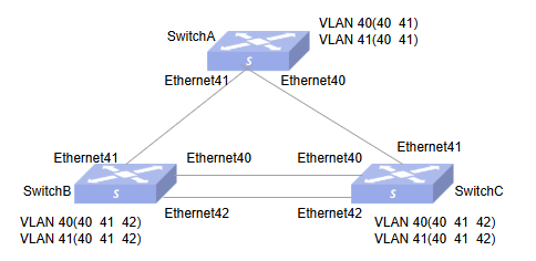
Section titled “MSTP Function Configuration”- Networking Requirements In a complex network, due to the need for redundancy and backup, network planners generally tend to deploy multiple physical links between devices, with one serving as the primary link and the others as backup links. This inevitably results in loops, which, if present in the network, may cause broadcast storms and corrupt MAC table entries. For this reason, loops can be prevented by deploying the MSTP protocol, which blocks redundant links in the Layer 2 network and prunes the network into a tree to eliminate loops. MSTP runs on the three devices. To implement load balancing between VLAN40 and VLAN41, MSTP introduces multiple instances. MSTP can set up VLAN mapping tables to associate VLANs with spanning tree instances.
- Topology
- Procedure
#Configure VLANs
Switch A
sonic# config terminalsonic(config)# vlan 40sonic(config)# vlan 41sonic(config)# interface ethernet 40/0sonic(config-if-0/40)# switchport access vlan 40sonic(config-if-0/40)# switchport trunk vlan 41sonic(config)# interface ethernet 41/0sonic(config-if-0/41)# switchport access vlan 40sonic(config-if-0/41)# switchport trunk vlan 41Switch B
sonic# config terminalsonic(config)# vlan 40sonic(config)# vlan 41sonic(config)# interface ethernet 40/0sonic(config-if-0/40)# switchport access vlan 40sonic(config-if-0/40)# switchport trunk vlan 41sonic(config)# interface ethernet 41/0sonic(config-if-0/41)# switchport access vlan 40sonic(config-if-0/41)# switchport trunk vlan 41sonic(config)# interface ethernet 42/0sonic(config-if-0/42)# switchport access vlan 40sonic(config-if-0/42)# switchport trunk vlan 41Switch C
sonic# config terminalsonic(config)# vlan 40sonic(config)# vlan 41sonic(config)# interface ethernet 40/0sonic(config-if-0/40)# switchport access vlan 40sonic(config-if-0/40)# switchport trunk vlan 41sonic(config)# interface ethernet 41/0sonic(config-if-0/41)# switchport access vlan 40sonic(config-if-0/41)# switchport trunk vlan 41sonic(config)# interface ethernet 42/0sonic(config-if-0/42)# switchport access vlan 40sonic(config-if-0/42)# switchport trunk vlan 41#MSTP configuration
Switch A
sonic# config terminalsonic(config)# mstp enablesonic(config)# mstp name region1sonic(config)# mstp instance 40sonic(config-mstp-instance-40)# vlan 40sonic(config-mstp-instance-40)# priority 1sonic(config)# mstp instance 41sonic(config-mstp-instance-41)# vlan 41Switch C
sonic# config terminalsonic(config)# mstp enablesonic(config)# mstp name region1sonic(config)# mstp instance 40sonic(config-mstp-instance-40)# vlan 40sonic(config-mstp-instance-40)# priority 1sonic(config)# mstp instance 41sonic(config-mstp-instance-41)# vlan 41sonic(config-mstp-instance-41)# interface priority 2 interface ethernet 0/42sonic(config-mstp-instance-41)# interface priority 4 interface ethernet 0/40Switch B
sonic# config terminalsonic(config)# mstp enablesonic(config)# mstp name region1sonic(config)# mstp instance 40sonic(config-mstp-instance-40)# vlan 40sonic(config-mstp-instance-40)# priority 1sonic(config)# mstp instance 41sonic(config-mstp-instance-41)# vlan 41- Verify the configuration.
sonic# show mstprole Flags: Root - Root, Desg - Designated, Altn - Alternate, Back - Backup, Mstr - Master, Disa - Disabledstate Flags: disc - Discard/Blocking/Listening, lear - Learning, forw - ForwardingSpanning-tree Mode: mstpvlan mst instance port_role_state------- -------------- ------------------------------------------------------------------Vlan40 40 Ethernet40(Desg)(forw) Ethernet41(Desg)(forw)Vlan41 41 Ethernet40(Root)(forw) Ethernet41(Desg)(forw)Send the stream to verify Send mutual traffic between ports to see how traffic is sent and received
| vlan | No. | Traffic forwarding results |
|---|---|---|
| 40 | 1 | Ports 41, 40 on Switch A forwarding traffic in Vlan 40 |
| 2 | Port 41 on Switch B forwarding traffic in Vlan 40 | |
| 3 | Ports 40,42 on Switch B not forwarding traffic in vlan 40 | |
| 4 | Ports 40, 41, 42 on Switch C forwarding traffic in Vlan 40 | |
| 41 | 5 | Ports 41, 40 on Switch A forwarding traffic in Vlan 41 |
| 6 | Ports 40, 41, 42 on Switch B , all forwarding traffic in Vlan 41 | |
| 7 | Port 42 on Switch C forwards traffic in Vlan 41 | |
| 8 | Ports 40, 41 on Switch C not forwarding traffic in Vlan 41 |