
PTP Configuration Guide
此内容尚不支持你的语言。
Introduction
Section titled “Introduction”The Precision Time Protocol (PTP) is a protocol designed to achieve high-precision clock synchronization in computer networks. It was originally developed to meet the stringent timing requirements of applications in fields such as industrial automation, telecommunications, and finance. The primary goal of PTP is to provide clock synchronization accuracy at the microsecond or even sub-microsecond level within computer networks. This high level of synchronization is critical in many domains, including high-frequency trading systems, power system synchronization, and time stamping for scientific research equipment.
Basic Concepts
Section titled “Basic Concepts”PTP Domain
A network that applies the PTP protocol is called a PTP domain. A network may contain multiple PTP domains, each of which is an independent PTP clock synchronization system. Within a single PTP domain, there is exactly one clock source, and all devices in the domain remain synchronized to this clock source.
Clock node types
The node in ptp domain is called clock node. There are three clock node types defined by IEEE 1588v2.
- OC(Ordinary Clock): only a single physical port participates in PTP time synchronization in a PTP domain. The device synchronizes time from an upstream node or distributes time to downstream nodes through this port.
- BC(Boundary Clock): two or more physical ports may participate in PTP time synchronization in a PTP domain. One port synchronizes time from an upstream device, while the remaining multiple ports distribute time to downstream devices. Additionally, when a clock node acts as a time source and simultaneously distributes time to downstream clock nodes through multiple PTP ports, it is also referred to as a BC.
- TC(Transparent Clock): TC does not synchronize time with any other device. TC has multiple PTP ports and only forwards PTP messages between these ports, applying transit delay correction. It does not synchronize time from any of its ports.
There are four clock node types defined by G8275.1.
- T-GM(Telecom Grandmaster): T-GM can only act as a Master, serving as a time source to provide timing.
- T-BC(Telecom Boundary Clock): T-BC has multiple PTP ports. One port synchronizes time from an upstream device, while the remaining multiple ports distribute time to downstream devices.
- T-TSC(Telecom Time Slave Clock): T-TSC can only act as a Slave, synchronizes time from an upstream node
- T-TC(Telecom Transparent clock): T-TC does not synchronize time with any other device. T-TC has multiple PTP ports and only forwards PTP messages between these ports, applying transit delay correction. It does not synchronize time from any of its ports.
There are three clock node types defined by G8275.2.
- T-GM(Telecom Grandmaster): T-GM can only act as a Master, serving as a time source to provide timing.
- T-BC-P(Telecom Boundary Clock For Partial Timing Support): T-BC-P has multiple PTP ports. One port synchronizes time from an upstream device, while the remaining multiple ports distribute time to downstream devices.
- T-TSC-P(Telecom Time Slave Clock For Partial Timing Support): T-TSC-P can only act as a Slave, synchronizes time from an upstream node.****PTP Port
A port on a device running the PTP protocol is called a PTP port. PTP ports can be classified into the following three roles:
- Master Port: A port that distributes synchronized time, which can exist on a BC or an OC
- Slave Port: A port that receives synchronized time, which can exist on a BC or an OC
- Passive Port: A port that neither receives nor distributes synchronized time, serving as an idle standby port, available only on a BC.
Master-Slave Relationship
The node devices within a PTP domain perform clock synchronization according to a specific master-slave hierarchy. The master-slave relationship is relative: a node that synchronizes time is called a slave node, and a node that distributes time is called a master node. A single device may simultaneously synchronize time from an upstream node and distribute time to downstream nodes. For a pair of clock nodes that are synchronizing with each other, the following master-slave relationships apply:
- The node that distributes synchronized time is called the master node, while the node that receives the synchronized time is called the slave node.
- The clock on the master node is referred to as the master clock, and the clock on the slave node is referred to as the slave clock.
- The port that distributes synchronized time is called the master port, and the port that receives synchronized time is called the slave port.
Grandmaster Clock
All clock nodes in a PTP domain are organized in a hierarchical structure, and the reference clock for the entire domain is the Grandmaster Clock (GMC). Through the exchange of PTP messages among clock nodes, the time of the Grandmaster Clock is ultimately synchronized across the entire PTP domain, hence it is also referred to as the time source. The Grandmaster Clock can be statically configured manually or dynamically elected using the Best Master Clock (BMC) or Alternate BMC algorithm.
How It Works
Section titled “How It Works”BMC algorithm
Section titled “BMC algorithm”In a PTP domain, the selection of the grandmaster clock and the establishment of port master-slave relationships are both accomplished using the Best Master Clock (BMC) algorithm. The BMC algorithm compares datasets carried in Announce messages exchanged among clock nodes to select the grandmaster clock and determine the state of each PTP port. In 1588v2, the BMC algorithm comparison rules are as follows:
- Clock Priority 1: A smaller priority1 value indicates higher priority.
- Clock Class: If priority1 values are equal, a smaller class value indicates higher priority.
- Clock Accuracy: If class values are equal, a smaller accuracy value indicates higher priority.
- Clock Priority 2: If accuracy values are equal, a smaller priority2 value indicates higher priority. Priority ranking order: priority1 > class > accuracy > priority2
In G.8275.1 and G.8275.2, the Alternate BMC algorithm comparison rules are as follows:
- Clock Class: A smaller class value indicates higher priority.
- Clock Accuracy: If class values are equal, a smaller accuracy value indicates higher priority.
- Clock Priority 2: If accuracy values are equal, a smaller priority2 value indicates higher priority.
- Local Clock Priority: If priority2 values are equal, a smaller priority value indicates higher priority.
- If local priorities are still equal, determine whether the clock class is less than or equal to 127:
- If the clock class is less than or equal to 127, in the absence of a superior clock node, two or more grandmaster clocks may be elected within the PTP domain. Slave nodes select the nearest grandmaster as their master, forming two separate spanning trees that do not exchange PTP messages with each other.
- If the clock class is greater than 127, the clock with the smaller clockID wins. Priority ranking order: class > accuracy > priority2 > priority.
PTP message type
Section titled “PTP message type”PTP achieves master-slave relationship establishment and time synchronization through message exchange between master and slave nodes. The PTP message types are shown in the table below.
Table 1 PTP message type
| Message Type | Description |
|---|---|
| Announce | Used for exchanging time source information between clock nodes to determine the master-slave hierarchy. |
| Sync | The Sync transmission mode can be divided into one-step and two-step:One-step: The Sync message contains the timestamp of its own transmission time.Two-step: The Sync message does not contain the timestamp of its transmission time; instead, it only records the transmission time, which is then carried in a subsequent Follow_Up message. |
| Follow_Up | Only used in two-step mode. After the Master sends a Sync message to the Slave, Follow_Up message is sent which carries the timestamp of when the Sync message was sent. |
| Delay_Req | In the Delay request-response synchronization method, the Slave sends a Delay_req message to the Master and records the timestamp of when the message was sent. |
| Delay_Resp | In the Delay request-response synchronization method, the Master sends a Delay_Resp message to the Slave. The message carries the timestamp of when the Delay_req message was received by the Master.. |
| Pdelay_Req | In the Peer Delay request-response synchronization method, the Slave sends a PDelay_Req message to the Master and records the timestamp of when the message was sent. |
| Pdelay_Resp | In the Peer Delay request-response synchronization method, the Master sends a PDelay_Resp message to the Slave. The message carries the timestamp of when the PDelay_Req message was received by the Master.. |
| Pdelay_Resp_Follow_Up | In the Peer Delay two-step time synchronization method, the Master sends a Pdelay_Resp_Follow_Up message to the Slave, carrying the timestamp of when the Pdelay_Resp message was transmitted at the Master. |
| Management | Transmits management information and commands to achieve clock management. |
| Signaling | Carries information, requests, and commands between clocks. |
Timestamp Carrying Method
Section titled “Timestamp Carrying Method”PTP calculates the path delay and time offset between master and slave devices by recording timestamps generated during message exchanges, thereby achieving time synchronization. There are two timestamp carrying modes:
- One-step mode: The Sync and Pdelay_Resp messages carry the timestamp of their own transmission time.
- Two-step mode: The Sync and Pdelay_Resp messages do not carry the timestamp of their transmission time; instead, the subsequent Follow_Up and Pdelay_Resp_Follow_Up messages carry the transmission timestamps. In two-step mode, the generation and announcement of time information are completed in two separate steps, which allows compatibility with devices that do not support timestamping the transmission time of Sync and Pdelay_Resp messages.
Delay Measurement Method
Section titled “Delay Measurement Method”There are two methods for delay measurement.
- E2E(End to End): Calculate the time offset based on the overall path delay between master and slave clocks.
- P2P(Peer to Peer): Calculate the time offset based on the delay of each individual link between master and slave clocks.
The process of the E2E mechanism (two-step mode) is shown in the figure.
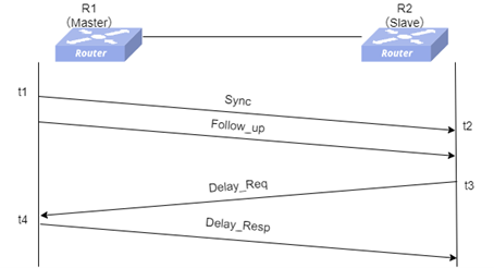
- The master clock sends a Sync message to the slave clock at time t1. In two-step mode, the slave clock records the time t2 after receiving the Sync message.
- The master clock sends a Follow_Up message to the slave clock. The slave clock obtains the transmission timestamp t1 of the Sync message from the Follow_Up message.
- The slave clock sends a Delay_Req message to the master clock. The slave clock records the transmission timestamp t3 of the Delay_Req message.
- After receiving the Delay_Req, the master clock sends a Delay_Resp message to the slave clock. The slave clock obtains the timestamp t4, indicating when the master clock received the Delay_Req message, from the Delay_Resp message.
At this point, the slave clock can use t1 to t4 to calculate the path delay and time offset.
- Path_Delay = [(t2 – t1) + (t4 – t3)]/2
- t2 = t1 + Path_Delay + Offset,
- Offset = t2 - t1 - Path_Delay = t2 - t1 - [(t2 – t1) + (t4 – t3)]/2 = [(t2 – t1) – (t4 – t3)]/2
The process of the P2P mechanism (two-step mode) is shown in the figure.
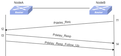
At this point, the NodeB can use t1 to t4 to calculate the path delay.
- Path_Delay = [(t2 – t1) + (t4 – t3)]/2
The clock offset of the slave clock relative to the master clock, Offset = time when the slave clock receives the Sync message – time when the master clock sends the Sync message – cumulative one-way delay of each link – total residence time of all TCs on the path.
Configure PTP
Section titled “Configure PTP”Enable PTP Feature
Section titled “Enable PTP Feature”Table 2 Enable PTP feature
| Purpose | Commands | Description |
|---|---|---|
| Enter global configuration view | configure terminal | - |
| Enable PTP feature | feature ptp state enable | - |
| Configure PTP autorestart | feature ptp autorestart enable | - |
Configure PTP Domain
Section titled “Configure PTP Domain”Table 3 Configure PTP domain
| Purpose | Commands | Description |
|---|---|---|
| Enter global configuration view | configure terminal | - |
| Create a PTP domain and enter PTP domain configuration view. | ptp domain domain-id | The range of domain-id is 0-127.When using the smpte-2059-2 profile, the configurable range for domain-id is 0–127,the default value is 127.When using the 1588v2 profile, the configurable range for domain-id is 0–127, the default value is 0.When using the aes67 profile, domain-id is fixed to 0.When using the g8275.1 profile, the configurable range for domain-id is 24–43, the default value is 24.When using the g8275.2 profile, the configurable range for domain-id is 44–63, with a default value of 44. |
| Configure PTP profile | ptp profile {smpte-2059-2|1588v2|aes67|g8275.1|g8275.2} | - |
| Configure PTP clock type | ptp mode clock_mode | When the configured PTP profile is smpte-2059-2, 1588v2, or aes67, the available clock types that can be configured are:oc bc e2etcp2ptc When the configured PTP profile is g.8275.1, the available clock types that can be configured are:t-gmt-bct-tsc t-tc When the configured PTP profile is g.8275.2, the available clock types that can be configured are:t-gmt-bc-p t-tsc-p |
| Configure timestamp carrying method | ptp clock-step {one_step|two_step} | The default method is one_step |
| Configure PTP message source IP | ptp source ip {A.B.C.D|A::B} | - |
| (Optional)Configure PTP message DSCP | ptp dscp dscp_value | The default is 56. |
Configure Clock parameters
Section titled “Configure Clock parameters”Table 4 Configure Clock parameters
| Purpose | Commands | Description |
|---|---|---|
| Enter global configuration view | configure terminal | - |
| Enter PTP domain configuration view | ptp domain domain-id | - |
| (Optional)Configure clock-id | ptp clock-id xxxxxx.xxxx.xxxxxx | By default, it is generated based on the device’s MAC address, with “fffe” inserted in the middle of the MAC address. |
| (Optional)Configure clock class | ptp class class | The default value is 248 |
| (Optional)Configure clock accuracy | ptp accuracy accuracy | The default value is 254 |
| (Optional)Configure PTP priority1 | ptp priority1 priority1 | The default priority1 is 128.When the configured PTP profile is smpte-2059-2, 1588v2, or aes67, the PTP priority1 parameter can be configured.When the configured PTP profile is g.8275.1 or g.8275.2, the PTP priority1 parameter is not supported. |
| (Optional)Configure PTP priority2 | ptp priority2 priority2 | The default priority2 is 128. |
Enable PTP on the interface
Section titled “Enable PTP on the interface”Table 5 Enable PTP on the interface
| Purpose | Commands | Description |
|---|---|---|
| Enter global configuration view | configure terminal | - |
| Enter Ethernet configuration view | interface ethernet interface-name | - |
| Bind the interface to PTP domain | ptp domain domain-id | - |
| Enable PTP | ptp enable | - |
| (Optional)Configure the PTP role | ptp role {dynamic|slave|master} | The default role is dynamic |
Configure Delay Measurement Method
Section titled “Configure Delay Measurement Method”Table 6 Configure Delay Measurement Method
| Purpose | Commands | Description |
|---|---|---|
| Enter global configuration view | configure terminal | - |
| Enter Ethernet configuration view | interface ethernet interface-name | - |
| (Optional)Configure Delay Measurement Method | ptp delay-mechanism {E2E|P2P} | The default mechanism is E2E |
Configure the message encapsulation mode
Section titled “Configure the message encapsulation mode”Table 7 Configure the message encapsulation mode
| Purpose | Commands | Description |
|---|---|---|
| Enter global configuration view | configure terminal | - |
| Enter Ethernet configuration view | interface ethernet interface-name | - |
| (Optional)Configure Message transmission mode | ptp transport{{ipv4 |ipv6} { multicast|unicast|mixed}|layer2} | - |
| (Optional)Configure the destination IP | ptp unicast master address {A.B.C.D|A::B} | - |
| (Optional)Configure the destination IP | ptp source ip {A.B.C.D|A::B} | - |
Configure message interval parameters
Section titled “Configure message interval parameters”Table 8 Configure message interval parameters
| Purpose | Commands | Description |
|---|---|---|
| Enter global configuration view | configure terminal | - |
| Enter Ethernet configuration view | interface ethernet interface-name | - |
| (Optional)Configure Announce Message transmission interval | ptp announce interval interval | When the configured PTP profile is smpte-2059-2, the range is [-3,1]. The default value is 0.When the configured PTP profile is 1588v2, the range is [0,4]. The default value is 1.When the configured PTP profile is aes67, the range is [0,4]. The default value is 1.When the configured PTP profile is g.8275.1, the interval cannot be modified. The default value is -3.When the configured PTP profile is g.8275.2, the range is [-3,0]. The default value is -3. |
| (Optional)Configure Announce message reception timeout multiplier | ptp announce timeout times | When the configured PTP profile is smpte-2059-2,1588v2,aes67, the announce message reception timeout multiplier can be modified.For other PTP profiles, the configuration cannot be modified.The range is [2,10]. The default value is 3 |
| (Optional)Configure Sync Message transmission interval | ptp sync-message interval interval | When the configured PTP profile is smpte-2059-2, the range is [-7,1]. The default value is -3.When the configured PTP profile is 1588v2, the range is [-7,1]. The default value is 0.When the configured PTP profile is aes67, the range is [-4,1]. The default value is -3.When the configured PTP profile is g.8275.1, the interval cannot be modified. The default value is -4.When the configured PTP profile is g.8275.2, the range is [-7,0]. The default value is -4. |
| (Optional)Configure Delay_Req Message transmission interval | ptp delay-req interval interval | When the configured PTP profile is smpte-2059-2, the range is [-3,5]. The default value is -3.When the configured PTP profile is 1588v2, the range is [-7,5]. The default value is 0.When the configured PTP profile is aes67, the range is [-4,5]. The default value is 0.When the configured PTP profile is g.8275.1, the interval cannot be modified. The default value is -4.When the configured PTP profile is g.8275.2, the range is [-7,0]. The default value is -4. |
| (Optional)Configure PDelay_Req Message transmission interval | ptp pdelay-req interval interval | When the configured PTP profile is smpte-2059-2, the range is [-3,5]. The default value is -3.When the configured PTP profile is 1588v2, the range is [-7,5]. The default value is 0.When the configured PTP profile is aes67, the range is [-4,5]. The default value is 0. |
(Optional)Configure SM-TLV
Section titled “(Optional)Configure SM-TLV”In the SMPTE-2059-2 standard, SM TLV (Stream Mapping Type-Length-Value) is a format used to transmit timecode and synchronization information, enabling the delivery and management of time synchronization information in multi-device and multi-system environments to ensure precise synchronization among devices. Therefore, this function is only available when using the smpte-2059-2 profile.
Enable SM-TLV
After enabling SM-TLV, the device supports handling of daylight saving time events. When a BC receives daylight saving time information, it records the time jump, prepares in advance for the transition, performs the time adjustment when the designated time is reached, and forwards the message to the OC clock. This ensures that during the start and end of daylight saving time, the system clock advances or retreats by one hour, preventing time inconsistencies in synchronization caused by time jumps. Daylight saving time, also known as “daylight saving time” or “summer time”, is a system that artificially adjusts local time to conserve energy. The uniform time used during this period is referred to as “daylight saving time”.
Table 9 Enable SM-TLV
| Purpose | Commands | Description |
|---|---|---|
| Enter global configuration view | configure terminal | - |
| Enter PTP domain configuration view | ptp domain domain-id | - |
| Enable SM-TLV | ptp sm-tlv enable | When the configured PTP profile is smpte-2059-2, the SM-TLV is supported.For other PTP profiles, SM-TLV configuration is not supported.Only the GM needs to configure SM-TLV |
Configure timecode parameters
After enabling SM-TLV, the default frame rate (default-frame-rates) can be configured on the GM, providing a timing reference that affects the synchronization of all devices. As a relay device, the BC forwards SM-TLV information to ensure smooth data flow throughout the PTP domain. The OC receives the SM-TLV data and applies the included timecode and synchronization information to maintain synchronization with the PTP domain.
Table 10 Configure timecode parameters
| Purpose | Commands | Description |
|---|---|---|
| Enter global configuration view | configure terminal | - |
| Enter PTP domain configuration view | ptp domain domain-id | - |
| Configure default-frame-rates | ptp sm-tlv default-frame-rates numerator denominator | - |
| Enable drop-frame timecode | ptp sm-tlv time-address-flags drop-frame | - |
| Enable color-frame timecode | ptp sm-tlv time-address-flags color-frame | - |
Display and Maintenance
Section titled “Display and Maintenance”Table 11 Display and Maintenance
| Purpose | Commands | Description |
|---|---|---|
| Display PTP state | show ptp clock [domain-id] | domain-id: the created PTP domain |
| Display SM-TLV info | show ptp clock sm-tlv domain-id | domain-id: the created PTP domain |
| Display the PTP configuration of the interface. | show ptp interface ethernet interface_name | - |
| Display packet statistics. | show ptp counters {interface ethernet interface_name | domain domain-id} | - |
Typical Configuration Example
Section titled “Typical Configuration Example”SMPTE multicast communication method
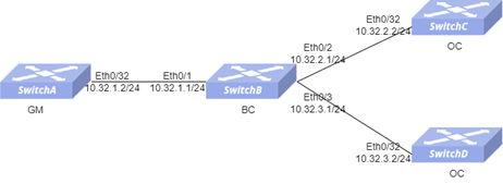
Section titled “SMPTE multicast communication method”- Networking Requirements In the network, SwitchA acts as the clock source and needs to synchronize time to SwitchC and SwitchD, with all three devices connected to SwitchB. The customer has high requirements for time accuracy and requires the use of the SMPTE-2059-2 standard and IPv4 UDP multicast communication mode, with one-step timestamping and the E2E delay measurement mechanism.

- Procedure SwitchA Configure Interface IP and Loopback0 IP
interface ethernet 0/32 ip address 10.32.1.2/24 exit!interface loopback 0 ip address 172.16.1.179/32 exitConfigure PTP domain
!ptp domain 127 ptp profile smpte-2059-2 ptp mode oc ptp clock-step one_step ptp clock-id 000000.fffe.000179 ptp priority1 100 ptp class 200 ptp source ip 172.16.1.179 exitEnable PTP on the interface
!interface ethernet 0/32 ptp domain 127 ptp enableSwitchB Configure Interface IP and Loopback0 IP
interface ethernet 0/1 ip address 10.32.1.1/24 exit!interface ethernet 0/2 ip address 10.32.2.1/24 exit!interface ethernet 0/3 ip address 10.32.3.1/24 exit!interface loopback 0 ip address 172.16.1.166/32 exitConfigure PTP domain
!ptp domain 127 ptp profile smpte-2059-2 ptp mode bc ptp clock-step one_step ptp clock-id 000000.fffe.000166 ptp priority1 120 ptp source ip 172.16.1.166 exitEnable PTP on the interface
!interface ethernet 0/1 ptp domain 127 ptp enable!interface ethernet 0/2 ptp domain 127 ptp enable!interface ethernet 0/3 ptp domain 127 ptp enableSwitchC Configure Interface IP and Loopback0 IP
interface ethernet 0/32 ip address 10.32.2.2/24 exit!interface loopback 0 ip address 172.16.1.174/32 exitConfigure PTP domain
!ptp domain 127 ptp profile smpte-2059-2 ptp mode oc ptp clock-step one_step ptp clock-id 000000.fffe.000174 ptp source ip 172.16.1.174Enable PTP on the interface
!interface ethernet 0/32 ptp domain 127 ptp enableSwitchD Configure Interface IP and Loopback0 IP
interface ethernet 0/32 ip address 10.32.3.2/24 exit!interface loopback 0 ip address 172.16.1.141/32 exitConfigure PTP domain
!ptp domain 127 ptp profile smpte-2059-2 ptp mode oc ptp clock-step one_step ptp clock-id 000000.fffe.000141 ptp source ip 172.16.1.141Enable PTP on the interface
!interface ethernet 0/32 ptp domain 127 ptp enable- Verify the configuration
Verfify PTP state on the SwitchB
SwitchB# show ptp clockDomain: 127Profile: smpte-2059-2Clock Mode: BCClock Step: one_stepDscp: 56Source IP Address: 0.0.0.0Local Clock Identity: 000000.fffe.000166Local Clock Accuracy: 0xFELocal Clock Class: 248Local Clock Priority1: 120Local Clock Priority2: 128ports: Ethernet1,Ethernet2,Ethernet3Grandmaster Clock Identity: 000000.fffe.000179Grandmaster Clock Accuracy: 0xfeGrandmaster Clock Class: 200Grandmaster Clock Priority1: 100Grandmaster Clock Priority2: 128Parent Port Identity: 1Servo State: lockedOffset To Master: 4Path Delay: 222Max Steps Removed: 255Local Time: 1986040939445Verfify PTP state on the SwitchC
SwitchC# show ptp clockDomain: 127Profile: smpte-2059-2Clock Mode: OCClock Step: one_stepDscp: 56Source IP Address: 0.0.0.0Local Clock Identity: 000000.fffe.000174Local Clock Accuracy: 0xFELocal Clock Class: 248Local Clock Priority1: 128Local Clock Priority2: 128ports: Ethernet32Grandmaster Clock Identity: 000000.fffe.000179Grandmaster Clock Accuracy: 0xfeGrandmaster Clock Class: 200Grandmaster Clock Priority1: 100Grandmaster Clock Priority2: 128Parent Port Identity: 1Servo State: lockedOffset To Master: -8Path Delay: 244Max Steps Removed: 255Local Time: 1986041830647Verfify PTP state on the SwitchD
SwitchD# show ptp clockDomain: 127Profile: smpte-2059-2Clock Mode: OCClock Step: one_stepDscp: 56Source IP Address: 0.0.0.0Local Clock Identity: 000000.fffe.000141Local Clock Accuracy: 0xFELocal Clock Class: 248Local Clock Priority1: 128Local Clock Priority2: 128ports: Ethernet32Grandmaster Clock Identity: 000000.fffe.000179Grandmaster Clock Accuracy: 0xfeGrandmaster Clock Class: 200Grandmaster Clock Priority1: 100Grandmaster Clock Priority2: 128Parent Port Identity: 2Servo State: lockedOffset To Master: 5Path Delay: 245Max Steps Removed: 255Local Time: 1987152330444SMPTE unicast communication method
Section titled “SMPTE unicast communication method”- Networking Requirements In the network, SwitchA acts as the clock source and needs to synchronize time to SwitchC and SwitchD, with all three devices connected to SwitchB. The customer has high requirements for time accuracy and requires the use of the SMPTE-2059-2 standard and IPv4 UDP unicast communication mode, with two-step timestamping and the E2E delay measurement mechanism.
- Procedure SwitchA Configure Interface IP and Loopback0 IP
interface ethernet 0/32 ip address 10.32.1.2/24 exit!interface loopback 0 ip address 172.16.1.179/32 exitConfigure PTP domain
!ptp domain 127 ptp profile smpte-2059-2 ptp mode oc ptp clock-step two_step ptp clock-id 000000.fffe.000179 ptp priority1 100 ptp class 200 ptp source ip 172.16.1.179 exitEnable PTP on the interface
!interface ethernet 0/32 ptp domain 127 ptp enable ptp transport ipv4 unicast ptp source ip 10.32.1.2SwitchB Configure Interface IP and Loopback0 IP
interface ethernet 0/1 ip address 10.32.1.1/24 exit!interface ethernet 0/2 ip address 10.32.2.1/24 exit!interface ethernet 0/3 ip address 10.32.3.1/24 exit!interface loopback 0 ip address 172.16.1.166/32 exitConfigure PTP domain
!ptp domain 127 ptp profile smpte-2059-2 ptp mode bc ptp clock-step two_step ptp clock-id 000000.fffe.000166 ptp priority1 120 ptp source ip 172.16.1.166 exitEnable PTP on the interface
!interface ethernet 0/1 ptp domain 127 ptp enable ptp transport ipv4 unicast ptp source ip 10.32.1.1 ptp unicast master address 10.32.1.2!interface ethernet 0/2 ptp domain 127 ptp enable ptp source ip 10.32.2.1 ptp transport ipv4 unicast!interface ethernet 0/3 ptp domain 127 ptp enable ptp source ip 10.32.3.1 ptp transport ipv4 unicastSwitchC Configure Interface IP and Loopback0 IP
interface ethernet 0/32 ip address 10.32.2.2/24 exit!interface loopback 0 ip address 172.16.1.174/32 exitConfigure PTP domain
!ptp domain 127 ptp profile smpte-2059-2 ptp mode oc ptp clock-step two_step ptp clock-id 000000.fffe.000174 ptp source ip 172.16.1.174Enable PTP on the interface
!interface ethernet 0/32 ptp domain 127 ptp enable ptp source ip 10.32.2.2 ptp transport ipv4 unicast ptp unicast master address 10.32.2.1SwitchD Configure Interface IP and Loopback0 IP
interface ethernet 0/32 ip address 10.32.3.2/24 exit!interface loopback 0 ip address 172.16.1.141/32 exitConfigure PTP domain
!ptp domain 127 ptp profile smpte-2059-2 ptp mode oc ptp clock-step two_step ptp clock-id 000000.fffe.000141 ptp source ip 172.16.1.141Ehable PTP on the interface
!interface ethernet 0/32 ptp domain 127 ptp enable ptp source ip 10.32.3.2 ptp transport ipv4 unicast ptp unicast master address 10.32.3.1- Verify the configuration Verfify PTP state on the SwitchB
SwitchB# show ptp clockDomain: 127Profile: smpte-2059-2Clock Mode: BCClock Step: two_stepDscp: 56Source IP Address: 0.0.0.0Local Clock Identity: 000000.fffe.000166Local Clock Accuracy: 0xFELocal Clock Class: 248Local Clock Priority1: 120Local Clock Priority2: 128ports: Ethernet1,Ethernet2,Ethernet3Grandmaster Clock Identity: 000000.fffe.000179Grandmaster Clock Accuracy: 0xfeGrandmaster Clock Class: 200Grandmaster Clock Priority1: 100Grandmaster Clock Priority2: 128Parent Port Identity: 1Servo State: lockedOffset To Master: 0Path Delay: 233Max Steps Removed: 255Local Time: 2101144339563Verfify PTP state on the SwitchC
SwitchC# show ptp clockDomain: 127Profile: smpte-2059-2Clock Mode: OCClock Step: two_stepDscp: 56Source IP Address: 0.0.0.0Local Clock Identity: 000000.fffe.000174Local Clock Accuracy: 0xFELocal Clock Class: 248Local Clock Priority1: 128Local Clock Priority2: 128ports: Ethernet32Grandmaster Clock Identity: 000000.fffe.000179Grandmaster Clock Accuracy: 0xfeGrandmaster Clock Class: 200Grandmaster Clock Priority1: 100Grandmaster Clock Priority2: 128Parent Port Identity: 1Servo State: lockedOffset To Master: 3Path Delay: 244Max Steps Removed: 255Local Time: 2101245256928Verfify PTP state on the SwitchD
SwitchD# show ptp clockDomain: 127Profile: smpte-2059-2Clock Mode: OCClock Step: two_stepDscp: 56Source IP Address: 0.0.0.0Local Clock Identity: 000000.fffe.000141Local Clock Accuracy: 0xFELocal Clock Class: 248Local Clock Priority1: 128Local Clock Priority2: 128ports: Ethernet32Grandmaster Clock Identity: 000000.fffe.000179Grandmaster Clock Accuracy: 0xfeGrandmaster Clock Class: 200Grandmaster Clock Priority1: 100Grandmaster Clock Priority2: 128Parent Port Identity: 2Servo State: lockedOffset To Master: 8Path Delay: 245Max Steps Removed: 255Local Time: 2103456162289