
ARP/ND Configuration Guide
此内容尚不支持你的语言。
Introduction
Section titled “Introduction”ARP (Address Resolution Protocol) is a protocol for obtaining MAC addresses based on IP addresses. Main frame sends messages broadcasting an ARP request containing the target IP address to all hosts on the local area network and receives return messages, which determines the physical address of the target; upon receipt of the return packets, the IP address and physical address are stored in the local ARP cache and retained for a certain period of time, and the ARP cache is queried directly on the next request to save resources.
Basic Concepts
Section titled “Basic Concepts”Dynamic ARP
Section titled “Dynamic ARP”Dynamic ARP table entries are automatically generated and maintained by the ARP protocol through ARP packets, and can be aged and updated, and can be overwritten by static ARP table entries. When the aging time is reached or the interface is down, the corresponding dynamic ARP table entry will be deleted.
Static ARP
Section titled “Static ARP”Static ARP table entries are configured and maintained manually and will not be aged out and overwritten by dynamic ARP table entries. Configuring static ARP table entries can increase the security of communication. When the network resources of the group network are more abundant, you can choose to deploy static ARP and fix the mapping relationship between IP addresses and MAC addresses.
ARP Proxy
Section titled “ARP Proxy”If the hosts belong to the same subnet but are not on the same physical network, and the gateway devices connected to the hosts have different gateway addresses, then for the hosts to communicate with each other, ARP proxy must be enabled on the switch interfaces connected to the hosts. When the switch has ARP proxy enabled, it responds to ARP requests for IP addresses within the same subnet using its own MAC address.
ARP Configuration
Section titled “ARP Configuration”ARP default setting
Section titled “ARP default setting”The default setting of ARP is shown in the table below.
Table 1 ARP default setting
| Parameters | Default value |
|---|---|
| Aging time of dynamic ARP table entries | 300 seconds |
| ARP Proxy | Not Enabled |
| ARP probe interval | 6 seconds |
| ARP probe times | 5 times |
Configure static ARP
Section titled “Configure static ARP”Configure the static ARP table entry protects the ARP table from being overwritten, but the configuration effort is high and it is not suitable for network environments where the host IP address may change, recommended for smaller networks.
Table 2 Configure static ARP
| Purpose | Commands | Description |
|---|---|---|
| Enter global configuration view. | configure terminal | - |
| Configure a static ARP entry. | arp static A.B.C.D HH:HH:HH:HH:HH:HH interface {ethernet|vlan|link-aggregation} interface-name[.subinterface-number] | - |
Configure global ARP timeout
Section titled “Configure global ARP timeout”Table 3 Configure global ARP timeout
| Purpose | Commands | Description |
|---|---|---|
| Enter global configuration view. | configure terminal | - |
| Configure ARP timeout. | arp timeout aging-time | interval-time , range [1-65535], in units of seconds. |
Configure ARP timeout for interface
Section titled “Configure ARP timeout for interface”Table 4 Configure ARP timeout for interface
| Purpose | Commands | Description |
|---|---|---|
| Enter global configuration view. | configure terminal | - |
| Enter interface configuration view. | interface {ethernet interface-name[.subinterface-number] |link-aggregation lag-id[.subinterface-number]|vlan vlan-id} | - |
| Configure ARP timeout. | arp timeout aging-time | interval-time , range [1-65535], in units of seconds. |
Configure ARP probe parameters
Section titled “Configure ARP probe parameters”Table 5 Configure global ARP probe parameters
| Purpose | Commands | Description |
|---|---|---|
| Enter global configuration view. | configure terminal | - |
| Configure the probe interval. | arp probe interval interval-time | interval-time , range [1-65535], in units of seconds. |
| Configure the probe times. | arp probe times num | num range [1-65535], in units of seconds |
Configure ARP probe parameters for interface
Section titled “Configure ARP probe parameters for interface”Table 6 Configure ARP probe parameters for interface
| Purpose | Commands | Description |
|---|---|---|
| Enter global configuration view | configure terminal | - |
| Enter interface configuration view. | interface {ethernet interface-name[.subinterface-number] |link-aggregation lag-id[.subinterface-number]|vlan vlan-id} | - |
| Configure the probe interval | arp probe interval interval-time | interval-time , range [1-65535], in units of seconds. |
| Configure the probe times | arp probe times num | num range [1-65535], in units of seconds |
Configure ARP to host route
Section titled “Configure ARP to host route”Enabling ARP to HOST route translation converts ARP table entries learned by the TOR device into host routes that can be propagated to other devices via BGP. Users can configure ARP to HOST route translation policies. This series provides two levels of conversion policies.
- Level 1: Port Policy
The action of port policy is available as permit/deny/pass. It is required to configure the default policy for all ports first, and then the special policy. If the incoming port matches the configured interface, the special policy is used; if it does not match, the default policy is used. If the policy is permit or deny, the conversion will be performed directly or not, without matching the next level Network policy; if the policy is pass, the next level Network policy will decide whether to convert or not.
- Level 2: Network Policy
The action of network policy is available as permit/deny. It is required to configure the default policy for network first, and then the special policy. If the neighbor IP matches the configured network, then the special policy is used; if not, then the default policy is used.
Table 7 Configure ARP to HOST Route
| Purpose | Commands | Description |
|---|---|---|
| Enter global configuration view | configure terminal | - |
| Enter ARP to HOST configuration view | arp-to-host | - |
| Enable ARP to HOST | convert enable [vrf vrf-name] | By default, the VRF parameter enables the default VRF |
| Configure the ARP to HOST port route policy | policy port {ethernet|link-aggregation} interface-name {permit|deny|pass} | Port policy applied to global configuration |
| Configure the ARP to HOST default route policy or networtk route policy | policy [vrf vrf-name] {port default {permit|deny|pass}|network default {permit|deny}|network A.B.C.D/M {permit|deny}} | vrfname VRF name, default is the default VRF.A.B.C.D/M is an IPv4 address with prefix length. |
Configure ARP proxy
Section titled “Configure ARP proxy”ARP proxy has two modes:
- Default mode: In this mode, when the switch receives an ARP request from the same network segment, it replies with the gateway’s MAC address.
- EVPN mode: This mode is used in EVPN scenarios to facilitate Layer 3 communication between hosts under different VTEPs. When ARP proxy is enabled on the gateway VLAN, the switch replies to ARP requests from the same network segment with the actual MAC address of the host.
Table 8 Configure ARP proxy
| Purpose | Commands | Description |
|---|---|---|
| Enter global configuration view. | configure terminal | - |
| Enter interface configuration view. | interface {ethernet interface-name[.subinterface-number] |link-aggregation lag-id[.subinterface-number]|vlan vlan-id} | - |
| Enable ARP Proxy. | arp proxy [mode default] | - |
Configure extend ARP proxy
Section titled “Configure extend ARP proxy”There are two extended features for ARP proxy:
- ARP Active Detection Feature This feature is enabled in Layer 2 networks where silent terminals (terminals that do not actively send ARP packets) are present. When this feature is activated, if the switch receives an ARP request and the target IP in the packet belongs to the same network segment, the switch will actively send an ARP request to probe.
- ARP Reply Packet Learning Feature By default, the switch only learns the source IP from ARP request packets. When this feature is enabled, upon receiving an ARP reply packet, the switch will add the source IP to the dynamic ARP table.
Table 9 Configure extend ARP proxy
| Purpose | Commands | Description |
|---|---|---|
| Enter global configuration view. | configure terminal | - |
| Enter interface configuration view. | interface {ethernet interface-name[.subinterface-number] |link-aggregation lag-id[.subinterface-number]|vlan vlan-id} | - |
| Enable silent terminal active detection. | arp proxy extend request | - |
| Enable learning of ARP Reply packets. | arp proxy extend reply | - |
Disable ARP flooding
Section titled “Disable ARP flooding”Disabling ARP flooding is applicable in scenarios that demand high performance, low latency, or enhanced security. For instance, in large-scale virtualized environments, the frequent migration of virtual machines can result in a surge of ARP requests across the network. Without proper control, ARP flooding can trigger broadcast storms, thereby increasing network load and degrading performance. Moreover, in VXLAN Overlay networks, ARP flooding can cause unnecessary traffic spread, impacting bandwidth efficiency. By activating the ARP proxy feature and disabling ARP flooding, switches can directly handle ARP requests, which significantly reduces broadcast traffic. Furthermore, disabling ARP flooding helps in mitigating ARP spoofing attacks, thus bolstering network security.
Table 10 Disable ARP flooding
| Purpose | Commands | Description |
|---|---|---|
| Enter global configuration view. | configure terminal | - |
| Disable ARP flooding. | arp broadcast disable | This command takes effect globally. |
Display and Maintenance
Section titled “Display and Maintenance”Table 11 ARP Display and Maintenance
| Purpose | Commands | Description |
|---|---|---|
| Display ARP entries. | show arp | - |
| Display ARP to host summary configuration. | show arp-to-host summary | summary: show ARP to HOST basic informationpolicy: show ARP to HOST rule information |
| Display ARP to host detailed configuration. | show arp-to-host policy | - |
| Clear all dynamic ARP entries. | clear neighbor all | - |
| Clear the dynamic ARP entries of the interface. | clear neighbor interface {ethernet|link-aggregation|vlan} {interface_name[.subinterface-number]} | - |
Typical Configuration Example
Section titled “Typical Configuration Example”Configure ARP Proxy
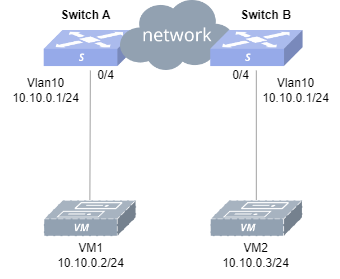
Section titled “Configure ARP Proxy”- Networking Requirements Two users on the same subnet are isolated into two different physical networks by different physical routers. Now, it is necessary for these users in the same subnet, but in different physical networks, to communicate with each other.
- Topology
- Procedure
In this example, to simplify the networking, Layer 3 reachability between hosts is achieved by deploying a directly connected link (ethernet 0/0) and static routes on Device A and B.
#Configure an interconnect link and a static route between Device A and B.
sonic(config)# interface ethernet 0/0sonic(config-if-0/0)# ip address 11.0.0.1/24sonic(config-if-0/0)# exitsonic(config)# ip route 10.10.0.3/32 11.0.0.2#Configure a VLAN and IP.
sonic(config)# vlan 10sonic(config-vlan-10)# exitsonic(config)# interface vlan 10sonic(config-vlanif-10)# ip address 10.10.0.1/24sonic(config)# interface ethernet 0/4sonic(config-if-0/4)# switchport access vlan 10#Enable ARP proxy.
sonic(config-vlanif-10)# interface vlan 10sonic(config-vlanif-10)# arp proxy mode defaultDevice B
#Configure an interconnect link and a static route between Device A and B.
sonic(config)# interface ethernet 0/0sonic(config-if-0/0)# ip address 11.0.0.2/24sonic(config-if-0/0)# exitsonic(config)# ip route 10.10.0.2/32 11.0.0.1#Configure a VLAN and IP.
sonic(config)# vlan 10sonic(config-vlan-10)# exitsonic(config)# interface vlan 10sonic(config-vlanif-10)# ip address 10.10.0.1/24sonic(config)# interface ethernet 0/4sonic(config-if-0/4)# switchport access vlan 10#Enable ARP proxy.
sonic(config-vlanif-10)# interface vlan 10sonic(config-vlanif-10)# arp proxy mode defaultHosts
#Configure VM1’s IP address as 10.10.0.2/24 and VM2’s IP as 10.10.0.3/24.
- Verification Let VM1 send NS messages to VM2 and check the ARP neighbor table on VM1. It is shown that the VM2 MAC is the MAC of VLAN 10. VM1 and VM2 can ping each other.
Introduction
Section titled “Introduction”The ND (Neighbor Discovery) protocol is a key protocol for IPv6, which combines protocols such as ARP, ICMP route discovery, and ICMP redirection from IPv4 and improves them. As a foundational protocol for IPv6, the ND protocol also provides prefix discovery, neighbor unreachability detection, duplicate address detection, and Stateless Address Autoconfiguration(SLAAC).
Basic Concepts
Section titled “Basic Concepts”Dynamic ND
Section titled “Dynamic ND”Dynamic ND table entries are automatically generated and maintained by the ND protocol through ND packets, and can be aged and updated, and can be overwritten by static ND table entries. When the aging time is reached or the interface is down, the corresponding dynamic ND table entry will be deleted.
Static ND
Section titled “Static ND”Static ND table entries are configured and maintained manually and will not be aged out and overwritten by dynamic ND table entries. Configuring static ND table entries can increase the security of communication. When the network resources of the group network are more abundant, you can choose to deploy static ND and fix the mapping relationship between IP addresses and MAC addresses.
ND Proxy
Section titled “ND Proxy”If hosts belong to the same network segment but on different physical networks, or hosts belong to the same network segment in the same physical network but cannot communicate with each other at Layer 2, you can enable ND proxy on the connected interface of the switch to achieve intercommunication between hosts. When the switch enables the ND proxy, it will use its own MAC as the source MAC and the destination host’s IPv6 address as the source IP to reply to the source host with the NA message, replacing the destination host to reply to the same network segment NS request.
SLAAC is a stateless auto-address configuration mechanism in IPv6 that uses RS (Router Solicitation) messages and RA (Router Advertisement) messages to complete the stateless auto-configuration process between IPv6 routers and IPv6 hosts. The host discovers the IPv6 router on the link through RS messages, and the IPv6 router advertises the IPv6 address prefix information to the host through RA messages, and the host automatically configures the IPv6 global unicast address after receiving the IPv6 prefix information. RADV (Router Advertisement Message) is a message broadcast by the IPv6 router to the switches in the local network, which is the core component of the SLAAC mechanism. Users can manually configure whether the interface sends RA messages and the time interval for sending RA messages, as well as configure the relevant parameters in the RA messages to be advertised to other devices.
ND Configuration
Section titled “ND Configuration”ND Default Setting
Section titled “ND Default Setting”The default setting of ND is shown in the table below.
Table 12 ND Default Setting
| Parameters | Default value |
|---|---|
| Aging time of dynamic ND table entries | 300 seconds |
| ND Proxy | Not Enabled |
| ND probe interval | 6 seconds |
| ND probe times | 5 times |
| RA notification | disable |
| MTU of the link for RA notification | 9216 |
| RA managed-flag | off |
| RA other-config-flag | off |
| RA on-link-flag | on |
| RA autonomous-flag | on |
| Maximum time interval for RA notifications | 600s |
| Minimum time interval for RA notifications | 200s |
Configure static ND
Section titled “Configure static ND”Configure the static ND table entry protects the ND table from being overwritten, but the configuration effort is high and it is not suitable for network environments where the host IP address may change, recommended for smaller networks.
Table 13 Configure Static ND
| Purpose | Commands | Description |
|---|---|---|
| Enter global configuration view | configure terminal | - |
| Configure a static ND entry | ndp static X:X::X:X*/M HH:HH:HH:HH:HH*:HH interface {ethernet interface-name[.subinterface-number]|link-aggregation lag-id[.subinterface-number]|vlan vlan-id} | - |
Configure ND to host route
Section titled “Configure ND to host route”Enabling ND to host route translation converts ND table entries learned by the TOR device into host routes that can be propagated to other devices via BGP. Users can configure ND to host route translation policies. This series provides two levels of conversion policies.
- Level 1: Port Policy
The action of port policy is available as permit/deny/pass. It is required to configure the default policy for all ports first, and then the special policy. If the incoming port matches the configured interface, the special policy is used; if it does not match, the default policy is used. If the policy is permit or deny, the conversion will be performed directly or not, without matching the next level Network policy; if the policy is pass, the next level Network policy will decide whether to convert or not.
- Level 2: Network Policy
The action of network policy is available as permit/deny. It is required to configure the default policy for network first, and then the special policy. If the neighbor IP matches the configured network, then the special policy is used; if not, then the default policy is used.
Table 14 Configure ND to HOST Route
| Purpose | Commands | Description |
|---|---|---|
| Enter global configuration view. | configure terminal | - |
| Enter ND to host configuration view. | arp-to-host | - |
| Enable ND to host. | convert enable [vrf vrf-name] | Applied to the default VRF when not specified. |
| Set default port policy. | policy [vrf vrf-name] port default {permit|deny|pass} | - |
| (Optional) Set policy for specific port. | policy [vrf vrf-name] port {ethernet|link-aggregation} interface-num {permit|deny|pass} | - |
| (Optional) Set default network policy. | policy [vrf vrf-name] network default {permit|deny} | - |
| (Optional) Set policy for specific network. | policy [vrf vrf-name] network X:X::X:X/M {permit|deny} | - |
Configure ND Proxy
Section titled “Configure ND Proxy”Table 15 Configure ND Proxy
| Purpose | Commands | Description |
|---|---|---|
| Enter global configuration view. | configure terminal | - |
| Enter interface configuration view. | interface {ethernet interface-name[.subinterface-number]|link-aggregation lag-id[.subinterface-number]|vlan vlan-id} | - |
| Enable ND Proxy. | nd proxy mode default | - |
Configure IPv6 Neighbor Discovery
Section titled “Configure IPv6 Neighbor Discovery”Table 16 Configure IPv6 Neighbor Discovery
| Purpose | Commands | Description |
|---|---|---|
| Enter global configuration view | configure terminal | - |
| Enable RA notification. | radv enable | - |
| Enter interface configuration view | interface {ethernet interface-name[.subinterface-number] |link-aggregation lag-id[.subinterface-number]|vlan vlan-id} | - |
| Configure prefix information for RA notification. | radv prefix X:X::X:X/M | - |
| (Optional) Configure DNS information for RA notification. | radv dns-server X:X::X:X | - |
| (Optional) Configure the MTU of the link for RA notification. | radv link-mtu mtu | Ensure that all nodes on the same link use the same MTU value |
| (Optional) Configure route information for RA notification. | radv route-information X:X::X:X/M [preference {low|high|medium}] | - |
| (Optional) Set the managed-flag to on. | radv managed-flag | This configuration is used to determine whether hosts uses stateful protocol for IPv6 address autoconfiguration, and the default is off. |
| (Optional) Set the other-config-flag to on. | radv other-config-flag | This configuration is used to determine whether hosts uses stateful protocol for autoconfiguration of other (non-address) information, and the default is off. |
| (Optional) Set the flag of on-link to off. | radv offlink | - |
| (Optional) Set the flag of autonomous to off. | radv no-autonomous | - |
| (Optional) Set the maximum and minimum time interval between two RA notifications. | radv ra-interval MaxRtrAdvInterval MinRtrAdvInterval | Set the maximum time interval for RA notifications in seconds, the default value is 600.Set the minimum time interval for RA notifications in seconds, the default value is 600. |
| Commit the configuration to take effect. | radv commit | - |
Disable ND broadcast
Section titled “Disable ND broadcast”Display and Maintenance
Section titled “Display and Maintenance”Table 17 Display and Maintenance
| Purpose | Commands | Description |
|---|---|---|
| Display IPv6 neighbors. | show ndp [interface] {ethernet interface-name[.subinterface-number]|link-aggregation lag-id[.subinterface-number]|vlan vlan-id} [X:X::X:X/M] | - |
| Display ND to host configuration. | show arp-to-host summary | - |
| Display ND to host detailed configuration. | show arp-to-host policy | - |
| Show RADV configuration. | show radv | - |
Typical Configuration Example
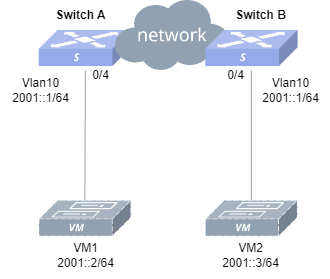
Section titled “Typical Configuration Example”- Networking Requirements Two users on the same subnet are isolated into two different physical networks by different physical routers. Now, it is necessary for these users in the same subnet, but in different physical networks, to communicate with each other.
Configure ND Proxy
Section titled “Configure ND Proxy”- Topology
- Procedure
In this example, to simplify the networking, Layer 3 reachability between hosts is achieved by deploying a directly connected link (ethernet 0/0) and static routes on Device A and B.
Device A
#Configure an interconnect link and a static route between Device A and B.
sonic(config)# interface ethernet 0/0sonic(config-if-0/0)# ip address 2000::1/64sonic(config-if-0/0)# exitsonic(config)# ipv6 route 2001::3/128 2000::2#Configure a VLAN and IP.
sonic(config)# vlan 10sonic(config-vlan-10)# exitsonic(config)# interface vlan 10sonic(config-vlanif-10)# ip address 2001::1/64sonic(config)# interface ethernet 0/4sonic(config-if-0/4)# switchport access vlan 10#Enable ND proxy.
sonic(config-vlanif-10)# interface vlan 10sonic(config-vlanif-10)# nd proxy mode defaultDevice B #Configure an interconnect link and a static route between Device A and B.
sonic(config)# interface ethernet 0/0sonic(config-if-0/0)# ip address 2000::2/64sonic(config-if-0/0)# exitsonic(config)# ipv6 route 2001::2/128 2000::1#Configure a VLAN and IP.
sonic(config)# vlan 10sonic(config-vlan-10)# exitsonic(config)# interface vlan 10sonic(config-vlanif-10)# ip address 2001::1/64sonic(config)# interface ethernet 0/4sonic(config-if-0/4)# switchport access vlan 10#Enable ND proxy.
sonic(config-vlanif-10)# interface vlan 10sonic(config-vlanif-10)# nd proxy mode defaultHosts
#Configure VM1’s IPv6 address as 2001::2/64 and VM2’s IPv6 address as 2001::3/64.
- Verification
Let VM1 send NS messages to VM2 and check the IPv6 neighbor table on VM1. It is shown that the VM2 MAC is the MAC of VLAN 10. VM1 and VM2 can ping each other.