
VxLAN Configuration Guide
此内容尚不支持你的语言。
Introduction
Section titled “Introduction”VXLAN as a network virtualization technology helps us to achieve scenarios such as multi-tenant expansion and VM migration. However, traditional VXLANs are established through manual configuration, which is complex to deploy and has no control surface, and address learning is done through multicast-based flooding, which generates a large number of flood packets and is not suitable for large-scale network. EVPN (Ethernet Virtual Private Network), using a mechanism similar to BGP/MPLS IP VPN, automatically establishes VXLAN tunnels and automatically synchronizes MAC and IP addresses through MP-BGP (Multi-protocol Extensions for Border Gateway Protocol), which is a good solution to these problems.. EVPN, as a Layer 2 VPN technology, the control plane uses MP-BGP to announce EVPN routing information, and the data plane supports VXLAN encapsulation for forwarding packets.
Basic Concepts
Section titled “Basic Concepts”BGP Neighbors
BGP neighbors are divided into IBGP and EBGP.
- IBGP neighbor IBGP means that the neighbor is located in the same AS as the local router. When IBGP is deployed, Route Reflector (RR) can be introduced to simplify full-connection configuration. The RR discovers and receives BGP connections initiated by VTEPs and forms a Client list, reflecting the routes received from a VTEP to all other VTEPs. The RR can be deployed in a Spine, a Leaf or a standalone device.
- EBGP neighbor EBGP means that the neighbor and local router are located in different AS. When EBGP is deployed, RR is not required and BGP automatically sends EVPN packets received from EBGP neighbors to other EBGP and IBGP neighbors, and Spine is equivalent to the RR function. In general, the asn differs from device to device, so EBGP is mostly used in SONiC. If redundant Leaf is used, the asn is the same for the pair of Leafs.
Symmetric IRB
In EVPN networks, VTEP can do both Layer 2 Bridge forwarding and Layer 3 Router routing functions, hence called Integrated Bridging and Routing (IRB). In a distributed gateway, IRB forwarding can be divided into two types: symmetric IRB and asymmetric IRB.
- Symmetric IRB refers to the fact that at the Ingress gateway and the Egress gateway, both do only the L3 routing function (or only the bridging function if they are on the same network segment). In this mode, each distributed gateway only needs to configure the VNI where the virtual machine hanging below it is located, and it does not need to maintain ARPs for all hosts or virtual machines within this tenant, but only a small number of ARPs corresponding to other distributed gateways.
- Asymmetric IRB refers to the fact that at the Ingress gateway do both the L2 Bridge and L3 routing function, and at the Egress gateway do only the L2 Bridge functions. The following 2 concepts, L3VNI and RouterMAC, are introduced in symmetric IRB.
- L3VNI means that when traffic is forwarded between distributed gateways via VXLAN tunnels, traffic belonging to the same tenant (VRF) is identified by L3VNI, which is uniquely associated with a VRF (VPN instance) and ensures service isolation between different tenants.
- The RouterMAC address of a gateway is a unique local MAC address owned by each distributed gateway that is used to identify the local machine. This MAC is used to forward Layer 3 traffic between gateways through VXLAN tunnels. When packets are forwarded between gateways, the inner MAC address of the packet is the RouterMAC address of the egress gateway. The symmetric IRB optimizes the ARP and MAC address tables in each VTEP to provide better scalability based on the overall number of VNIs that can be supported in a VXLAN Overlay network. the SONiC implements a symmetric IRB forwarding model.
VRF
VRF, Virtual Routing Forwarding. VRF is used to resolve local routing conflicts. Each VRF can be seen as a virtual router, consisting of the following elements: an independent routing table/forwarding table, a set of interfaces belonging to this VRF, and a set of routing protocols exclusively used for this VRF.
Packet Type
Section titled “Packet Type”Legacy BGP-4 can only manage IPv4 unicast routing information, which is limited for applications using other network layer protocols (e.g. IPv6, multicast, etc.) when propagating across AS. MP-BGP is an extension of BGP-4 to provide support for multiple network layer protocols, and the update packet carries three pieces of information related to IPv4 in the packets used by BGP: the NLRI (Network Layer Reachability Information) field, the Next_Hop attribute, and the Aggregator attribute. MP-BGP reflects the network layer protocol information in the NLRI and Next_Hop fields, and introduces two new optional non-transition path attributes, as shown in the following table.
Table 1 Optional Non-Transition Path Attributes
| Properties | Description |
|---|---|
| MP_REACH_NLRI | Multiprotocol Reachable NLRI, used to publish reachable routes and next-hop information |
| MP_UNREACH_NLRI | Multiprotocol Unreachable NLRI, used to undo unreachable routes |
EVPN defines the following types of BGP EVPN route types in MP_REACH_NLRI and MP_UNREACH_NLRI by extending the NLRI of the BGP protocol for learning and publishing host information between different sites in a Layer 2 network.
MAC/IP Advertisement Route (Type-2 route)
Section titled “MAC/IP Advertisement Route (Type-2 route)”As mentioned earlier, in the absence of a control plane, MAC learning for hosts in VXLAN network is done by flooding. To solve this problem, EVPN has defined Type-2 route, i.e. MAC/IP route, with the packet format shown below.
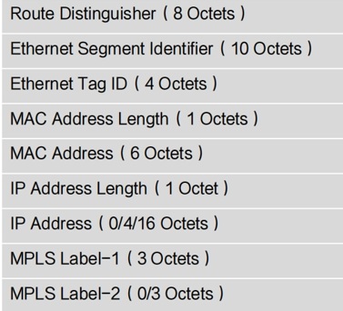
Type-2 route achieves the following main things.
- Host MAC address advertise It can carry host MAC information and is used to inform each other of the MAC information of local downstream hosts between EVPN peers, enabling Layer 2 intercommunication with hosts on the same subnet.
- Host ARP advertise Can carry both host MAC+IP, i.e. host ARP, for passing ARP table entries of local downstream hosts between EVPN peers, for ARP broadcast suppression and VM migration.
- Host IP route advertise The IP Address Length and IP Address fields are the destination address of the host IP route, while the MPLS Label-2 field must carry a Layer 3 VNI, at which point the MAC/IP route, also known as an IRB-type route, can mutually notify each other of the local downstream host IP route that has been obtained, realizing Layer 3 intercommunication with hosts across subnets in a distributed gateway.
Inclusive Multicast Ethernet Tag Route (Type-3 route)
Section titled “Inclusive Multicast Ethernet Tag Route (Type-3 route)”EVPN defines Type-3 route, i.e. Inclusive multicast routes, which are mainly used in the VXLAN control plane for VTEP auto-discovery and dynamic establishment of VXLAN tunnels. The packet format is shown in the figure below.
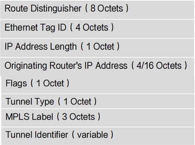
As a VTEP in a BGP EVPN peer relationship, it exchanges Layer 2 VNI and VTEP IP address information with peers via Type-3 routes. Where the Originating Router’s IP Address field is the local VTEP IP address and the MPLS Label field is the Layer 2 VNI. If the peer VTEP IP address is reachable by a Layer 3 route and the peer’s VNI is the same as the local one, a VXLAN tunnel to the peer is established and a mapping is created and a header replication table is created that for subsequent BUM packet forwarding.
IP Prefix Advertisement Route (Type-5 route)
Section titled “IP Prefix Advertisement Route (Type-5 route)”In addition, EVPN defines Type-5 route, i.e. ip-prefix routes, declaring their routing packet format as shown in the following figure.
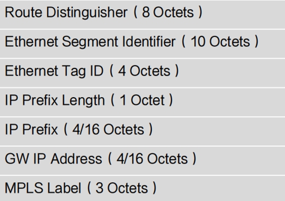
The IP Prefix Length and IP Prefix fields can carry either the host IP address or the network segment address. When carrying the host IP address, it is the same as the host IP route announcement function of Type-2 route; when carrying the network segment address, it is mainly used to implement hosts in VXLAN networks to access external networks. Type-5 route is used to structure Tunnel Route and implement ARP proxy, which are not currently used in EVPN scenarios, but are used in PICFA scenarios.
Working Principle
Section titled “Working Principle”VXLAN Tunnel Establishment
Section titled “VXLAN Tunnel Establishment”Enable EVPN on Leaf, configure local VTEP, after configuring the mapping, it will announce EVPN Type-3 route, carrying the main information of local vtep + vni; the remote Leaf receives the announcement to see if the same vni is configured locally, if so, then establish L2VXLAN tunnel; similarly, the remote Leaf announces it, and after the local receives it, then establish the L2VXLAN tunnel locally. After the VM comes online, it sends a free ARP, which Leaf learns and updates its own FDB, ARP table and at the same time announces an EVPN Type-2 route carrying L3vni. The remote Leaf receives the announcement and first establishes the L3VXLAN tunnel, then establishes the ARP cache for the remote VM (remote VM real ip + real mac) and the next hop information for the tunnel (remote vtep ip + corresponding RouterMAC).
MAC/IP Route Announcements and Learning
Section titled “MAC/IP Route Announcements and Learning”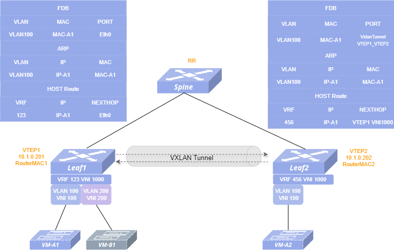
As shown above, VM-A1 comes online, VTEP-1 synchronizes the learned MAC and host route of VM-A1 to RR via type-2 route; RR receives it and synchronizes the route to all neighbors. VTEP-2 receives it and sends down the MAC of VM-A1 to the FDB table, and the IP of VM-A1 forms a 32-bit host route to the routing table of its VRF.
Traffic Forward
Section titled “Traffic Forward”Interworking between VMs on the same Leaf is the most basic Layer 2 and 3 forwarding, and is not related to VXLAN tunnels, so it will not be described here. Cross-device VM interworking is carried out through VXLAN tunnels. The following will describe in detail the flow of cross-device Layer 2 forwarding and cross-device Layer 3 forwarding in EVPN scenarios, using VM-A1 to VM-A2 communication and VM-B1 to VM-A2 communication as examples. Background: VM-A2 is online, EVPN interaction learning on each Leaf has been completed, tunnels have been established and each forwarding table has been generated.
Layer 2 Forward
VM-A1 communicates with VM-A2.
- VM-A1 first sends ARP requests for the MAC address of VM-A2. Upon receipt of this request, Leaf1 looks up the table based on the Layer 3 port (Vlan100) and destination IP (IP-A2) of the received packet and replies to the result (MAC-A2) to VM-A1.
- VM-A1 sends an ICMP packet to VM-A2, where dip is IP-A2 and dmac is MAC-A2. Leaf1 receives it, queries the FDB table based on the packet vlan and dmac, the query hits, and encapsulates it to go through the tunnel. The outer dmac of the encapsulated packet is the corresponding RouterMAC (MAC-Spine), and the outer dip is the opposite end VTEP IP, vni is 100.
- The encapsulated packet is forwarded to Leaf2 via Spine. Leaf2 parses the packet and finds that the outer dmac is the local mac, the outer dip is the local VTEP IP, and the VXLAN mapping (VNI100-VLAN100) exists, so it is unencapsulated and then forwards it to VM-A2 by querying the FDB table based on the inner dmac (MAC-A2).
Layer 3 Forward
VM-B1 communicates with VM-A2.
- VM-B1 first sends an ARP request for the gateway MAC, and Leaf1 receives the request and replies with the gateway MAC to VM-B1.
- VM-B1 sends an ICMP packet to VM-A2, where dip is IP-A2 and dmac is the gateway MAC (MAC-Leaf1). dmac is found to be the local MAC upon receipt by Leaf1, so Layer 3 forwarding is performed, the routing table is queried based on the VRF (Vrf123) and dip where the packet vlan is located, the query hits, the next hop is the peer VTEP IP, encapsulated go through the tunnel, the outer dmac of the encapsulated packet is the corresponding RouterMAC (MAC-Spine), the outer dip is the VTEP IP of the opposite end, vni is 1000, and the inner dmac is the MAC of the VTEP of the opposite end.
- The encapsulated packet is forwarded by Spine to Leaf2, which parses the packet and finds that the outer dmac is the local mac, the outer dip is the local VTEP IP, and the VXLAN mapping (VNI1000-Vrf456) exists, so it is unencapsulated; in turn, the inner dmac is also the local MAC, which is forwarded at Layer 3, based on Vrf456 and dip query routing table, query hits, modify dmac to MAC-A2, and then forward to VM-A2.
Enhancements
Section titled “Enhancements”In addition to the basic functions, the SONiC also offers several enhancements.
ARP Suppression
Section titled “ARP Suppression”When the scale of virtual machines in the network expands, ARP broadcast will consume the network bandwidth and there will be the hidden danger of broadcast storms. To reduce the impact caused by ARP broadcast, we can suppress ARP flooding by means of ARP proxy. Turn off ARP flooding and enable ARP proxy on the Leaf device. When Leaf receives an ARP request from the local host, it will query the database and reply with the real MAC to the local host.
VM Migration
Section titled “VM Migration”In an EVPN scenario, when a host migrates from one Leaf node to another, the host sends free ARP packets, and the migrated Leaf refreshes the local host route/host ARP information based on the free ARP packet and advertises an EVPN type-2 route to the remote Leaf, directing traffic to the migrated Leaf. The difference between this route and the MAC/IP route advertised before the migration is that the BGP update packet carries a new extension group: MAC mobility, where the SeqNum field is incremented by 1 each time the migration takes place. When the remote Leaf receives packets with SeqNum larger than the local ARP, it updates its own MAC/IP routing information with the next hop pointing to the VTEP or gateway that advertised this route after the migration. The original VTEP, upon receiving this route update, revokes the previously advertised route.
Border
Section titled “Border”Border refers to a network edge device that is used for hosts in the overlay network to access the external network. Configuring routes in the VRF on a device configured as Border will synchronize these routes to the VXLAN network via EVPN type-5 route; different routes are configured in different VRFs, thus controlling access to the external network by hosts of different users in the VXLAN network.
EVPN Configuration
Section titled “EVPN Configuration”Table 2 Overview of EVPN Configuration Tasks
| Configuration Tasks | Description | Refer to | |
|---|---|---|---|
| Pre-configuration | Configure VLAN | Required | Configure VLAN |
| Configure VRF | Required | Configure VRF | |
| EVPN Related Configuration | Configure VTEP IP | Required | Configure VTEP IP |
| Configure Underlay BGP | Required | Configure Underlay BGP | |
| Configure Overlay BGP | Required | Configure Overlay BGP | |
| Configure VXLAN map | Required | Configure VXLAN map | |
| Configure ARP proxy | Optional | Configure ARP proxy |
Configure VLAN
It is required that the gateways (VLAN) of the VMs under the same L2 VNI must be the same, i.e., the IPs and MACs of the VLANs are the same, and the VLAN IDs can be different (because the VLAN IDs only work locally).
Table 3 Configure VLAN
| Purpose | Commands | Description |
|---|---|---|
| Enter global configuration view | configure terminal | - |
| Enter VLAN configuration view and create VLAN | vlan vlan-id | VLAN ID range: 1-4094 |
| Exit VLAN configuration view | exit | - |
| Enter VLANIF configuration view | interface vlan vlan-id | - |
| Set the IP for VLANIF | ip address A.B.C.D/M | - |
| Configure MAC for VLANIF | mac-address HH:HH:HH:HH:HH:HH | MAC address is not case sensitive |
| Exit VLANIF configuration view | exit | - |
| Enter interface configuration view. | interface {ethernet interface-name |link-aggregation lag-id } | - |
| Add VLAN member ports | switchport {trunk|access} vlan vlan-id | - |
Configure VRF
Section titled “Configure VRF”In the EVPN-MC-LAG scenario, it is required that the MAC of VRFs corresponding to the same L3 VNIs are the same on the master and standby devices deploying MC-LAG.
Table 4 Configure VRF
| Purpose | Commands | Description |
|---|---|---|
| Enter global configuration view | configure terminal | - |
| Enter the VRF configuration view and create VRF | vrf vrf-name | - |
| Set the MAC of VRF. (optional) | mac HH:HH:HH:HH:HH:HH | - |
| Exit VRF configuration view | exit | - |
| Enter VLANIF configuration view | interface vlan vlan-id | - |
| Bind the VLAN to the VRF | vrf vrf-name | - |
Configure VTEP IP
Section titled “Configure VTEP IP”It is recommended to configure a Loopback1 IP as the local VTEP IP.
Table 5 Configure VTEP IP
| Purpose | Commands | Description |
|---|---|---|
| Enter global configuration view | configure terminal | - |
| Enter Loopback 0 interface view | interface loopback 0 | - |
| Configure the IP address of Loopback 0 | ip address A.B.C.D/M | Since the IP address of Loopback0 will be used as the router-id when BGP neighbors are established, the IP address of Loopback0 is required to be unique. |
| Exit Loopback 0 interface view | exit | - |
| Enter Loopback 1 interface view | interface loopback 1 | - |
| Configure the IP address of Loopback 1 | ip address A.B.C.D/M | The IP address of Loopback1 will be used as the VTEP IP for VXLAN. |
| Exit Loopback 1 interface view | exit | - |
| Enter VXLAN view | interface vxlan vxlan-id | vxlan-id: VXLAN ID, range 0-9.CX308P-48Y-N-V2 and CX532P-N-V2 devices support this configurations in the range of 0-9, other devices can only be configured as 0 |
| Configure the local address of VTEP | source ip-address | Loopback1 IP is normally configured as VTEP IP |
Configure Underlay BGP
Section titled “Configure Underlay BGP”Create BGP neighbors and proactively advertise routes for VTEP IPs to be reachable by VTEP IPs.
Table 6 Configure Underlay BGP
| Purpose | Commands | Description |
|---|---|---|
| Enter global configuration view | configure terminal | - |
| Enter BGP view | router bgp asn | asn: local AS number |
| (Optional) Configure router identifier | bgp router-id A.B.C.D | - |
| Disable the ebgp-requires-policy | no bgp ebgp-requires-policy | - |
| Add BGP neighbors | neighbor neighbor_ip remote-as asn | - |
| Enter address-family view for ipv4 unicast | address-family ipv4 unicast | - |
| Advertise Loopback0 and Loopback1 IP route | network {A.B.C.D/M|A.B.C.D} | - |
Configure Overlay BGP
Section titled “Configure Overlay BGP”Configure Overlay BGP and advertise all VNIs.
Table 7 Configure Overlay BGP
| Purpose | Commands | Description |
|---|---|---|
| Enter global configuration view | configure terminal | - |
| Enter BGP view | router bgp asn | asn: local AS number |
| Add BGP neighbors | neighbor neighbor_ip remote-as asn | neighbor_ip: Neighbor’s Loopback0 IP, same below. |
| Configure ebgp-multihop | neighbor neighbor_ip ebgp-multihop max_hop | max_hop: Maximum hop count for BGP messages, its range is [1,255] |
| Configure source ip for BGP messages | neighbor neighbor_ip update-source loopback0_ip | loopback0_ip: Local Loopback0 IP |
| Enter address-family view of ipv4 unicast | address-family ipv4 unicast | - |
| Disable IPv4 for the BGP neighbor | no neighbor neighbor_ip activate | - |
| Exit address-family view | exit-address-family | - |
| Enter address-family view of l2vpn EVPN | address-family l2vpn evpn | - |
| Enable EVPN | neighbor neighbor_ip activate | - |
| Advertise all vni | advertise-all-vni | - |
Configure VXLAN Map
Section titled “Configure VXLAN Map”Configure Layer 2 and Layer 3 VXLAN map.
Table 8 Configure VXLAN Map
| Purpose | Commands | Description |
|---|---|---|
| Enter global configuration view. | configure terminal | - |
| Enter VLAN configuration view. | vlan vlan-id | - |
| Configure Layer 2 VXLAN Mappings. | vni vni-id | - |
| Exit current view. | exit | - |
| Enter VRF configuration view. | vrf vrf-name | - |
| Configure Layer 3 VXLAN mapping. | vni vni-id vxlan vxlan-id | - |
(Optional) Configure ARP Proxy
Section titled “(Optional) Configure ARP Proxy”Table 9 Configure the ARP Proxy
| Purpose | Commands | Description |
|---|---|---|
| Enter global configuration view | configure terminal | - |
| Disable arp broadcast | arp broadcast disable | - |
| Enter VLANIF configuration view. | interface vlan vlan-id | - |
| Configure the ARP proxy | arp proxy mode evpn | - |
Display and Maintenance
Section titled “Display and Maintenance”Table 10 EVPN Display and Maintenance
| Purpose | Commands | Description |
|---|---|---|
| Show VXLAN mapping table | show vxlan map | - |
| Check established VXLAN tunnels | show vxlan tunnel | - |
| Display the remote MAC entries synchronized via VXLAN | show vxlan remotemac {all|A.B.C.D} | - |
Typical Configuration Example
Section titled “Typical Configuration Example”Distributed Gateway Symmetric IRB
- Networking Requirements A large number of VMs are deployed in the data center of an enterprise, currently there are two subnets with a total of four VMs distributed on two Leaf switches, VM-A1, VM-A2 and VM-B1 on Leaf1 and VM-A3 on Leaf2. It is assumed that Layer 3 interworking has been implemented between each Leaf switch. It is now required to interwork between the VMs by means of BGP-EVPN. The ASN of each device is given in the topology
- Topology
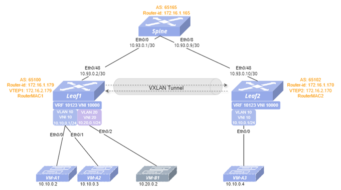
| Equipment | Interface | IP address |
|---|---|---|
| Spine | Eth 0/0 | 10.93.0.1/30 |
| Eth 0/8 | 10.93.0.9/30 | |
| Loopback0 | 172.16.1.165/32 | |
| Leaf1 | Eth 0/48 | 10.93.0.2/30 |
| Vlan10 | 10.10.0.1/24 | |
| Vlan20 | 10.20.0.1/24 | |
| Loopback0 | 172.16.1.179/32 | |
| Loopback1 | 172.16.2.179/32 | |
| Leaf2 | Eth 0/48 | 10.93.0.10/30 |
| Vlan10 | 10.10.0.1/24 | |
| Loopback0 | 172.16.1.170/32 | |
| Loopback1 | 172.16.2.170/32 |
- Configuration Roadmap (1)Check that the link status of the ports used on the switch is normal, and that all ports are stable in the UP state. (2)Configure the switch interface IP addresses and the Loopback0 IP address. (3)Configure the VTEP IP address on the Leaf devices. (4)Configure the Underlay BGP. (5)Configure the Overlay BGP. (6)Configure VLANs and add VLAN member ports, create VRF instances, and configure VLANIF interfaces. (7)Configure VXLAN VNI mapping.
4 Procedure
Spine
#Configure the switch interface IP addresses
interface ethernet 0/0 ip address 10.93.0.1/30 exit!interface ethernet 0/8 ip address 10.93.0.9/30 exit!interface loopback 0 ip address 172.16.1.165/32 exit#Configure underlay BGP
router bgp 65165 bgp router-id 172.16.1.165 no bgp ebgp-requires-policy bgp bestpath as-path multipath-relax neighbor PEER_to_Leaf peer-group neighbor PEER_to_Leaf remote-as external neighbor 10.93.0.2 peer-group PEER_to_Leaf neighbor 10.93.0.10 peer-group PEER_to_Leaf address-family ipv4 unicast network 172.16.1.165/32#Configure overlay BGP
router bgp 65165 neighbor PEER_to_Leaf_EVPN peer-group neighbor PEER_to_Leaf_EVPN remote-as external neighbor PEER_to_Leaf_EVPN ebgp-multihop 5 neighbor PEER_to_Leaf_EVPN update-source 172.16.1.165 neighbor 172.16.1.179 peer-group PEER_to_Leaf_EVPN neighbor 172.16.1.170 peer-group PEER_to_Leaf_EVPN address-family ipv4 unicast no neighbor PEER_to_Leaf_EVPN activate exit-address-family ! address-family l2vpn evpn neighbor PEER_to_Leaf_EVPN activate advertise-all-vni exit-address-familyexitLeaf1
#Configure the switch interface IP addresses
interface ethernet 0/48 ip address 10.93.0.2/30 exit!interface loopback 0 ip address 172.16.1.179/32 exit!interface loopback 1 ip address 172.16.2.179/32 exit#Configure VTEP IP
interface vxlan 0 source 172.16.2.179exit#Configure underlay BGP
router bgp 65100 bgp router-id 172.16.1.179 no bgp ebgp-requires-policy bgp bestpath as-path multipath-relax neighbor 10.93.0.1 remote-as 65165 address-family ipv4 unicast network 172.16.1.179/32 network 172.16.2.179/32#Configure overlay BGP
router bgp 65100 neighbor 172.16.1.165 remote-as 65165 neighbor 172.16.1.165 ebgp-multihop 5 neighbor 172.16.1.165 update-source 172.16.1.179 address-family ipv4 unicast no neighbor 172.16.1.165 activate address-family l2vpn evpn neighbor 172.16.1.165 activate advertise-all-vni exit-address-familyexit#Configure VLANs and add VLAN member ports, create VRF instances.
vlan 10 exit!vlan 20 exit!interface ethernet 0/0 switchport access vlan 10 exit!interface ethernet 0/1 switchport access vlan 10 exit!interface ethernet 0/2 switchport access vlan 20 exit!vrf 10123 mac 00:00:00:01:23:00 exit!arp broadcast disable!interface vlan 10 mac-address 00:00:00:10:00:00 vrf 10123 ip address 10.10.0.1/24 arp proxy mode evpn!interface vlan 20 mac-address 00:00:00:20:00:00 vrf 10123 ip address 10.20.0.1/24 arp proxy mode evpn#Configure VXLAN VNI mapping
vlan 10 vni 10!vlan 20 vni 20!vrf 10123 vni 10000exit-vrf!Leaf2
#Configure the switch interface IP addresses
interface ethernet 0/48 ip address 10.93.0.10/30 exit!interface loopback 0 ip address 172.16.1.170/32 exit!interface loopback 1 ip address 172.16.2.170/32 exit#Configure VTEP IP
interface vxlan 0 source 172.16.2.170exit#Configure underlay BGP
router bgp 65102 bgp router-id 172.16.1.170 no bgp ebgp-requires-policy bgp bestpath as-path multipath-relax neighbor 10.93.0.9 remote-as 65165 address-family ipv4 unicast network 172.16.1.170/32 network 172.16.2.170/32#Configure overlay BGP
router bgp 65102 neighbor 172.16.1.165 remote-as 65165 neighbor 172.16.1.165 ebgp-multihop 5 neighbor 172.16.1.165 update-source 172.16.1.170 address-family ipv4 unicast no neighbor 172.16.1.165 activate address-family l2vpn evpn neighbor 172.16.1.165 activate advertise-all-vni exit-address-familyexit#Configure VLANs and add VLAN member ports, create VRF instances.
vlan 10 exit!interface ethernet 0/0 switchport access vlan 10 exitvrf 10123 mac 00:00:00:01:23:01 exit!arp broadcast disable!interface vlan 10 mac-address 00:00:00:10:00:00 vrf 10123 ip address 10.10.0.1/24 arp proxy mode evpn#Configure VXLAN VNI mapping
vlan 10 vni 10!vrf 10123 vni 10000exit-vrf!- Configuration verification
Spine
#Display underlay BGP neighbors
sonic# show ip bgp summaryIPv4 Unicast Summary (VRF default):BGP router identifier 172.16.1.165, local AS number 65165 vrf-id 0BGP table version 9RIB entries 13, using 2392 bytes of memoryPeers 2, using 1447 KiB of memoryPeer groups 1, using 64 bytes of memoryNeighbor V AS MsgRcvd MsgSent TblVer InQ OutQ Up/Down State/PfxRcd PfxSnt Desc10.93.0.2 4 65100 1334 1334 0 0 0 01:58:22 7 7 N/A10.93.0.10 4 65102 133 133 0 0 0 01:58:22 7 7 N/ATotal number of neighbors 2#Display overlay BGP neighbors
sonic# show bgp l2vpn evpn summaryBGP router identifier 172.16.1.165, local AS number 65165 vrf-id 0BGP table version 0RIB entries 31, using 5704 bytes of memoryPeers 2, using 1447 KiB of memoryPeer groups 1, using 64 bytes of memoryNeighbor V AS MsgRcvd MsgSent TblVer InQ OutQ Up/Down State/PfxRcd PfxSnt Desc172.16.1.179 4 65100 196 328 0 0 0 00:05:52 4 10 N/A172.16.1.170 4 65102 1037 1081 0 0 0 02:42:12 4 10 N/ATotal number of neighbors 2Leaf1
#Display underlay BGP neighbors
sonic# show ip bgp summaryIPv4 Unicast Summary (VRF default):BGP router identifier 172.16.1.179, local AS number 65100 vrf-id 0BGP table version 9RIB entries 13, using 2392 bytes of memoryPeers 1, using 724 KiB of memoryPeer groups 0, using 0 bytes of memoryNeighbor V AS MsgRcvd MsgSent TblVer InQ OutQ Up/Down State/PfxRcd PfxSnt Desc10.93.0.1 4 65165 133 133 0 0 0 01:58:22 4 7 N/ATotal number of neighbors 1#Display overlay BGP neighbors
sonic# show bgp l2vpn evpn summaryBGP router identifier 172.16.1.179, local AS number 65100 vrf-id 0BGP table version 0RIB entries 151, using 27 KiB of memoryPeers 1, using 1447 KiB of memoryPeer groups 0, using 0 bytes of memoryNeighbor V AS MsgRcvd MsgSent TblVer InQ OutQ Up/Down State/PfxRcd PfxSnt Desc172.16.1.165 4 65165 196 328 0 0 0 00:05:52 6 10 N/ATotal number of neighbors 1#Display VXLAN Tunnels
sonic # show vxlan tunnel+--------------+-------+--------+-------+| RemoteVTEP | VNI | VLAN | VRF |+==============+=======+========+=======+| 172.16.2.170 | 10 | 10 | |+--------------+-------+--------+-------+| 172.16.2.170 | 10000 | | 10123 |+--------------+-------+--------+-------+Leaf2
#Display underlay BGP neighbors
sonic# show ip bgp summaryIPv4 Unicast Summary (VRF default):BGP router identifier 172.16.1.170, local AS number 65102 vrf-id 0BGP table version 4RIB entries 15, using 2392 bytes of memoryPeers 1, using 724 KiB of memoryPeer groups 0, using 0 bytes of memoryNeighbor V AS MsgRcvd MsgSent TblVer InQ OutQ Up/Down State/PfxRcd PfxSnt Desc10.93.0.9 4 65165 1231 1250 0 0 0 01:15:12 4 7 N/ATotal number of neighbors 1#Display overlay BGP neighbors
sonic# show bgp l2vpn evpn summaryBGP router identifier 172.16.1.179, local AS number 65100 vrf-id 0BGP table version 0RIB entries 151, using 27 KiB of memoryPeers 1, using 1447 KiB of memoryPeer groups 0, using 0 bytes of memoryNeighbor V AS MsgRcvd MsgSent TblVer InQ OutQ Up/Down State/PfxRcd PfxSnt Desc172.16.1.165 4 65165 32 28 0 0 0 00:08:44 6 10 N/ATotal number of neighbors 1#Display VXLAN Tunnels
sonic # show vxlan tunnel+--------------+-------+--------+-------+| RemoteVTEP | VNI | VLAN | VRF |+==============+=======+========+=======+| 172.16.2.179 | 10 | 10 | |+--------------+-------+--------+-------+| 172.16.2.179 | 10000 | | 10123 |+--------------+-------+--------+-------+The VMs under each Leaf ping each other and can ping through.
Static VXLAN
Section titled “Static VXLAN”Example of Layer 2 VXLAN Scenario Configuration
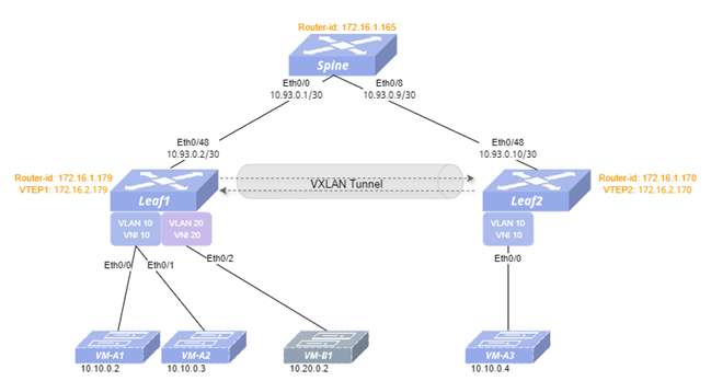
Section titled “Example of Layer 2 VXLAN Scenario Configuration”- Networking Requirements A company needs to implement Layer 2 interconnection between VMs under different Leaf devices through Layer 2 VXLAN.
- Topology
- Configuration Roadmap (1)Check that the link status of the ports used on the switch is normal, and that all ports are stable in the UP state. (2)Configure the switch interface IP addresses and the Loopback0 IP address. (3)Configure static routes to ensure reachability between Loopback IP addresses. (4)Configure the VTEP IP address on the Leaf devices. (5)Configure VLANs and add VLAN member ports. (6)Configure VXLAN VNI mapping and static MAC entries for the host.
- Procedure
Spine
Configure the switch interface IP addresses and the Loopback0 IP address.
interface ethernet 0/0 ip address 10.93.0.1/30 exit!interface ethernet 0/8 ip address 10.93.0.9/30 exit!interface loopback 0 ip address 172.16.1.165/32 exitConfigure static routes to ensure reachability between Loopback IP addresses.
!ip route 172.16.1.179/32 10.93.0.2!ip route 172.16.2.179/32 10.93.0.2!ip route 172.16.1.170/32 10.93.0.10!ip route 172.16.2.170/32 10.93.0.10Leaf1
Configure the switch interface IP addresses and the Loopback0 IP address.
interface ethernet 0/48 ip address 10.93.0.2/30 exit!interface loopback 0 ip address 172.16.1.179/32 exit!interface loopback 1 ip address 172.16.2.179/32 exitConfigure static routes to ensure reachability between Loopback IP addresses.
!ip route 172.16.1.170/32 10.93.0.1!ip route 172.16.2.170/32 10.93.0.1Configure the VTEP IP address on the Leaf devices.
interface vxlan 0 source 172.16.2.179exitConfigure VLANs and add VLAN member ports.
vlan 10 exit!vlan 20 exit!interface ethernet 0/0 switchport access vlan 10 exit!interface ethernet 0/1 switchport access vlan 10 exit!interface ethernet 0/2 switchport access vlan 20 exit!Configure VXLAN VNI mapping and static MAC entries for the hosts. There are MACs of VM.
VM-A1 MAC: 00:10:94:05:00:01 VM-A2 MAC: 00:10:94:05:00:02 VM-A3 MAC: 00:10:94:05:00:03 VM-B1 MAC: 00:20:94:05:00:01
!vlan 10 vni 10 exit!vlan 20 vni 20 exit!interface vxlan 0 vni 10 peer 172.16.2.170 vni 20 peer 172.16.2.170 exit!mac-address static 00:10:94:05:00:03 vlan 10 vxlan vni 10 peer 172.16.2.170Leaf2
Configure the switch interface IP addresses and the Loopback0 IP address.
interface ethernet 0/48 ip address 10.93.0.10/30 exit!interface loopback 0 ip address 172.16.1.170/32 exit!interface loopback 1 ip address 172.16.2.170/32 exitConfigure static routes to ensure reachability between Loopback IP addresses.
!ip route 172.16.1.179/32 10.93.0.9!ip route 172.16.2.179/32 10.93.0.9Configure the VTEP IP address on the Leaf devices.
interface vxlan 0 source 172.16.2.170exitConfigure VLANs and add VLAN member ports.
vlan 10 exit!vlan 20 exit!interface ethernet 0/0 switchport access vlan 10 exitConfigure VXLAN VNI mapping and static MAC entries for the hosts. There are MACs of VM.
VM-A1 MAC: 00:10:94:05:00:01VM-A2 MAC: 00:10:94:05:00:02VM-A3 MAC: 00:10:94:05:00:03VM-B1 MAC: 00:20:94:05:00:01!vlan 10 vni 10 exit!vlan 20 vni 20 exit!interface vxlan 0 vni 10 peer 172.16.2.179 vni 20 peer 172.16.2.179 exit!mac-address static 00:10:94:05:00:01 vlan 10 vxlan vni 10 peer 172.16.2.179mac-address static 00:10:94:05:00:02 vlan 10 vxlan vni 10 peer 172.16.2.179mac-address static 00:20:94:05:00:01 vlan 20 vxlan vni 20 peer 172.16.2.179Example of Layer 3 VXLAN Scenario Configuration
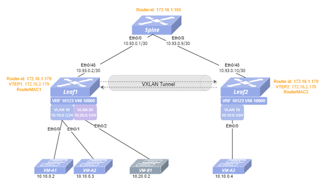
Section titled “Example of Layer 3 VXLAN Scenario Configuration”- Networking Requirements A company has a large number of VMs deployed on two servers, where VM-B1 and VM-A2 have different services and need to achieve Layer 3 interoperability. It is assumed that Layer 3 interworking is already in place between the Leaf switches (in this example, two Leafs are directly connected).
- Topology
- Configuration Roadmap (1)Check that the link status of the ports used on the switch is normal, and that all ports are stable in the UP state. (2)Configure the switch interface IP addresses and the Loopback0 IP address. (3)Configure static routes to ensure reachability between Loopback IP addresses. (4)Configure the VTEP IP address on the Leaf devices. (5)Configure VLAN and add VLAN member ports, create a VLAN Layer 3 interface, and create a VRF instance. (6)Configure VXLAN VNI mapping and static route entries for the host.
- Procedure
Spine
Configure the switch interface IP addresses and the Loopback0 IP address.
interface ethernet 0/0 ip address 10.93.0.1/30 exit!interface ethernet 0/8 ip address 10.93.0.9/30 exit!interface loopback 0 ip address 172.16.1.165/32 exitConfigure static routes to ensure reachability between Loopback IP addresses.
!ip route 172.16.1.179/32 10.93.0.2!ip route 172.16.2.179/32 10.93.0.2!ip route 172.16.1.170/32 10.93.0.10!ip route 172.16.2.170/32 10.93.0.10Leaf1
Configure the switch interface IP addresses and the Loopback0 IP address.
interface ethernet 0/48 ip address 10.93.0.2/30 exit!interface loopback 0 ip address 172.16.1.179/32 exit!interface loopback 1 ip address 172.16.2.179/32 exitConfigure static routes to ensure reachability between Loopback IP addresses.
!ip route 172.16.1.170/32 10.93.0.1!ip route 172.16.2.170/32 10.93.0.1Configure the VTEP IP address on the Leaf devices.
interface vxlan 0 source 172.16.2.179exitConfigure VLAN and add VLAN member ports, create a VLAN Layer 3 interface, and create a VRF instance.
!arp broadcast disable!vlan 10 exit!vlan 20 exit!interface ethernet 0/0 switchport access vlan 10 exit!interface ethernet 0/1 switchport access vlan 10 exit!interface ethernet 0/2 switchport access vlan 20 exit!vrf 10123 mac 00:00:00:01:23:00 exit!interface vlan 10 mac-address 00:00:00:10:00:00 vrf 10123 ip address 10.10.0.1/24 arp proxy mode default!interface vlan 20 mac-address 00:00:00:20:00:00 vrf 10123 ip address 10.20.0.1/24 arp proxy mode default!Configure VXLAN VNI mapping and static route entries for the host. There are IP addresses for hosts
VM-A1 10.10.0.2VM-A2 10.10.0.3VM-A3 10.10.0.4VM-B1 10.20.0.2vrf 10123 vni 10000exit-vrf!interface vxlan 0 vni 10000 peer 172.16.2.170 rmac 00:00:00:01:23:01!vrf 10123 ip route 10.10.0.4/32 172.16.2.170 vxlan-vni 10000 onlinkLeaf2
Configure the switch interface IP addresses and the Loopback0 IP address.
interface ethernet 0/48 ip address 10.93.0.10/30 exit!interface loopback 0 ip address 172.16.1.170/32 exit!interface loopback 1 ip address 172.16.2.170/32 exitConfigure static routes to ensure reachability between Loopback IP addresses
!ip route 172.16.1.179/32 10.93.0.9!ip route 172.16.2.179/32 10.93.0.9Configure the VTEP IP address on the Leaf devices
interface vxlan 0 source 172.16.2.170exitConfigure VLAN and add VLAN member ports, create a VLAN Layer 3 interface, and create a VRF instance.
!arp broadcast disable!vlan 10 exit!vlan 20 exit!interface ethernet 0/0 switchport access vlan 10 exit!vrf 10123 mac 00:00:00:01:23:01 exit!interface vlan 10 mac-address 00:00:00:10:00:00 vrf 10123 ip address 10.10.0.1/24 arp proxy mode default!interface vlan 20 mac-address 00:00:00:20:00:00 vrf 10123 ip address 10.20.0.1/24 arp proxy mode default!Configure VXLAN VNI mapping and static route entries for the host. There are IP addresses for hosts.
VM-A1 10.10.0.2VM-A2 10.10.0.3VM-A3 10.10.0.4VM-B1 10.20.0.2vrf 10123 vni 10000exit-vrf!interface vxlan 0 vni 10000 peer 172.16.2.179 rmac 00:00:00:01:23:00!vrf 10123 ip route 10.10.0.2/32 172.16.2.179 vxlan-vni 10000 onlink ip route 10.10.0.3/32 172.16.2.179 vxlan-vni 10000 onlink ip route 10.20.0.2/32 172.16.2.179 vxlan-vni 10000 onlink