
L2PT Configuration
Introduction
Section titled “Introduction”L2PT (Layer 2 Protocol Transparent Transmission) is a technology used to extend Local Area Network (LAN) connections across Wide Area Networks (WAN). Simply put, it allows Layer 2 protocol packets from user networks in different geographical locations (such as corporate headquarters and branch offices) to be transparently transmitted through the carrier network (or large enterprise backbone network) as if passing through a “dedicated tunnel.
Explanation of Principles
Section titled “Explanation of Principles”- On the user access side of the backbone network, the multicast destination MAC address of the original Layer 2 protocol packet is replaced with a specific multicast MAC address.
- After the MAC address is modified, the packet traverses the backbone network. Depending on the configured transparent transmission mode, the network decides whether to process the packet or not.
- When the Layer 2 protocol packet reaches the egress node, the device matches the packet against the configured mapping relationship between the special multicast destination MAC addresses and the Layer 2 protocols. It then restores the packet’s multicast destination MAC address to the standard one defined for that specific Layer 2 protocol. Finally, based on the configured transparent transmission mode, it decides whether to process the packet.
L2PT Configuration
Section titled “L2PT Configuration”| Configure Tasks | Instructions |
|---|---|
| Enter the interface configuration view | interface ethernet id |
| Configure the protocol packet to be discarded | l2protocol-packet {stp|lacp} disable |
| Enable L2PT | l2protocol-tunnel {stp|lacp|cdp|pvstp} enable |
Configuration Example
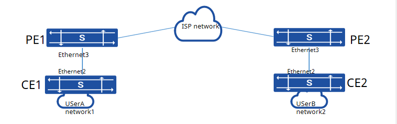
Section titled “Configuration Example”The CE devices are the edge devices of the enterprise located in different geographical networks, while PE1 and PE2 are the edge devices of the carrier network. The two enterprise networks are Layer 2 networks and are interconnected through the carrier network. To prevent loops in the Layer 2 network, the Spanning Tree Protocol (STP) is enabled, and the enterprise requires STP to run only within its own networks to form a correct spanning tree.
Procedure
- The configuration of CE1 and CE2 is the same, here is the example of CE1
- Create VLAN 100, 200 and add the corresponding physical interfaces to the VLAN
sonic(config)# vlan 100sonic(config)# interface ethernet 2sonic(config-if-2)# switchport trunk vlan 100sonic(config-if-2)# exitsonic(config)# stp mode stpsonic(config)# mstp enable- Add Ethernet3 interfaces of PE1 and PE2 to VLAN 100, and enable Layer 2 protocol tunneling on the PE devices
sonic(config)# interface ethernet 3sonic(config-if-3)# l2protocol-packet stp disablesonic(config-if-3)# l2protocol-tunnel stp enable- Verify configuration
sonic# show stp statusSpanning-tree Mode: stpvlan mst instance port_role_state------ -------------- --------------------------------------------Vlan100 0 Ethernet2(Root)(forw)