
Ethernet Link Aggregation Configuration
Introduction
Section titled “Introduction”Link Aggregation combines multiple physical links into one logical link to increase bandwidth, achieve traffic load balancing, and improve link reliability. Link aggregation has two modes: static aggregation and dynamic aggregation. Users can choose one of these modes based on their characteristics and the specific network setup.
- Static aggregation: After configuration, the selected/non-selected status of the ports is not affected by the network environment, making it relatively stable. However, it cannot adjust the selected/non-selected status of member ports based on the state of the peer device.
- Dynamic aggregation: It can adjust the selected/non-selected status of ports based on information from both ends, making it more flexible. However, the selected/non-selected status of member ports is more easily influenced by the network environment.
Explanation of Principles
Section titled “Explanation of Principles”Ethernet Link Aggregation bundles multiple physical interfaces into one logical interface, allowing bandwidth to be increased without hardware upgrades. A link aggregation interface can be used like a regular Ethernet interface to support various routing protocols and other services.
- Link Aggregation, Link Aggregation Group, and Link Aggregation Interface
Link aggregation is a technology that bundles several physical interfaces into a single logical interface to increase bandwidth and reliability.
A link aggregation group refers to the logical link formed by bundling several Ethernet links together.
Each aggregation group uniquely corresponds to a logical interface, which is referred to as the aggregation interface.
- Member Interfaces and Member Links
The physical interfaces that make up the aggregation interface are called member interfaces. The links corresponding to these member interfaces are known as member links.
- Dynamic Link Aggregation Working Mechanism
- Selecting a Reference Port: The reference port is chosen from the member ports on both ends of the aggregation link that are in the UP state.
- First, the device with the higher priority is selected from both ends of the aggregation link. If device priorities are the same, the system ID is compared; the lower the ID value, the higher the priority.
- Next, on the higher priority device, the port with the higher priority is chosen. The smaller the port priority number, the higher the priority. If port priorities are the same, the port with the smaller port number is prioritized and selected as the reference port.
- Determining the State of Member Ports: On the higher priority device, the state of the member ports is determined.
- If the local port is in the UP state and its peer port’s system ID matches the system ID of the reference port’s peer, the member port state is set to “selected.”
- If the local port is in the DOWN state, the member port state is “deselected.”
At the same time, the device with the lower priority will adjust the state of its member ports according to changes on the peer device, ensuring the consistency of member port states on both ends of the aggregation link.
Member Interface States within an Aggregation Group:
- S (selected): In this state, the member port can participate in data forwarding and is referred to as a “selected port.”
- D (deselected): In this state, the member port cannot participate in data forwarding and is referred to as a “deselected port.”
Ethernet Link Aggregation Configuration
Section titled “Ethernet Link Aggregation Configuration”| Configure Tasks | Instructions |
|---|---|
| Create a link aggregation group | Required |
| Add member interface to the aggregation group | Required |
| Configure the working mode of the aggregation group | Optional |
| Configure the system’s LACP priority | Optional |
| Configure the LACP system-id attribute | Optional |
| Configure the LACP fast rate attribute | Optional |
| Configure the LACP fallback attribute | Optional |
Creating a Link Aggregation Group
Section titled “Creating a Link Aggregation Group”| Operation | Command | Description |
|---|---|---|
| Enter the system configuration view | configure terminal | |
| Create a link aggregation group | interface link-aggregation |
Adding Member Interfaces to the Aggregation Group
Section titled “Adding Member Interfaces to the Aggregation Group”When configuring member ports for the aggregation group, the recommended process is as follows:
In system view, use the show running-config command to check if the ports have any attribute-related configurations (such as port isolation, VLAN configurations, etc.).
If such configurations exist, use the corresponding no commands to remove these configurations, ensuring the ports are in their default attribute state.
Once the ports are in the default state, add them to the created aggregation group.
| Operation | Command | Description |
|---|---|---|
| Enter the interface configuration view | interface ethernet interface-id | |
| Add member interface to the aggregation group | link-aggregation-group |
Configuring the Working Mode of the Aggregation Group
Section titled “Configuring the Working Mode of the Aggregation Group”| Operation | Command | Description |
|---|---|---|
| Enter the link aggregation group view | interface link-aggregation | |
| Configure the working mode of the aggregation group | mode {dynamic|static} |
Configuring the System’s LACP Priority
Section titled “Configuring the System’s LACP Priority”Configuring the system’s priority is important to distinguish the priority between the local device and the peer device in LACP mode. For a link aggregation group (LAG) to be established, both devices at either end must select the same active interfaces. When one device has a higher priority, the other device will select its active ports based on the higher-priority device, ensuring consistency of selected ports on both ends.
The lower the system’s LACP priority value, the higher the priority. By default, the system LACP priority is set to 65535.
If the priority is not configured, the devices will choose the active side based on the system ID, with the device having the smaller system ID becoming the active device. The system ID is typically based on the system MAC address. For example:
Switch A’s system MAC address: 60:eb:5a:00:ee:a7
Switch B’s system MAC address: 60:eb:5a:01:10:d3
The first three bytes of both MAC addresses are identical. When comparing the fourth byte, 00 (hex) is smaller than 01 (hex), so Switch A has a smaller MAC address and becomes the active device.
| Operation | Command | Description |
|---|---|---|
| Enter the link aggregation group view | interface link-aggregation | |
| Configure the system’s LACP priority | lacp system-priority |
Configuring the LACP System-ID Attribute
Section titled “Configuring the LACP System-ID Attribute”The system ID is used to identify a device in the LACP protocol. By default, the system ID is the MAC address of the system.
When system priority is not explicitly configured, the system ID is used to determine the priority between devices, with the device having the smaller system ID being given higher priority.
| Operation | Command | Description |
|---|---|---|
| Enter the link aggregation group view | interface link-aggregation | |
| Configure the LACP system-id attribute | lacp system-id <mac_address> |
Configuring the LACP Fast-Rate Attribute
Section titled “Configuring the LACP Fast-Rate Attribute”The fast-rate attribute enables the local device’s fast detection mechanism, reducing the LACP packet transmission interval from 30 seconds to 1 second per packet.
This configuration is particularly useful for networks that require high availability, where faster link failure detection and switchover to backup links are critical to minimize network downtime.
| Operation | Command | Description |
|---|---|---|
| Enter the link aggregation group view | interface link-aggregation | |
| Configure the LACP fast rate attribute | lacp fast-rate |
Configuring the LACP Fallback Attribute
Section titled “Configuring the LACP Fallback Attribute”The fallback attribute configures the LACP protocol for fast negotiation mode, enabling quick re-negotiation of the link aggregation group during a link failure.
Normally, LACP requires some time to re-establish the aggregation group if a link fails, which could cause network disruptions or delays, impacting reliability and performance. By enabling the fallback attribute, the system will bring the link aggregation group back up even if LACP negotiation fails, ensuring continuous network availability.
| Operation | Command | Description |
|---|---|---|
| Enter the link aggregation group view | interface link-aggregation | |
| Configure the LACP fallback attribute | lacp fallback |
Configuration Example
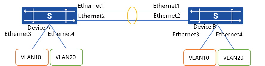
Section titled “Configuration Example”Network requirements
- Device A and Device B are connected to each other via their respective Ethernet0, 1.
- Configure Layer 2 static link aggregation groups on Device A and Device B, and implement VM interworking in VLAN 10 and VLAN 20, respectively.
Procedure
- Configuration Device A
# Create VLAN10 and add Ethernet3 to this VLAN.
sonic(config)# vlan 10sonic(config)# interface ethernet 3sonic(config-if-3)# switchport access vlan 10# Create VLAN 20 and add Ethernet4 to this VLAN.
sonic(config)# vlan 20sonic(config)# interface ethernet 4sonic(config-if-4)# switchport access vlan 20# Create dynamic aggregation port PortChannel0001, and add Ethernet0, 1 to this aggregation group.
sonic(config)# interface link-aggregation 1sonic(config-lagif-1)# exitsonic(config)# interface ethernet 1sonic(config-if-1)# link-aggregation-group 1sonic(config-if-1)# exitsonic(config)# interface ethernet 2sonic(config-if-2)# link-aggregation-group 1sonic(config-if-2)# exit- Configure Device B Similar to Device A, the configuration process is omitted.
Verify configuration View configuration information by show interfaces portchannel.
sonic# show link-aggregation summaryFlags: A - active, I - inactive, Up - up, Dw - Down, N/A - not available, S - selected, D - deselected, * - not synced No. Team Dev Protocol Ports----- --------------- ----------- ------------- 0001 PortChannel0001 LACP(A)(Dw) Ethernet1(D) 0002 PortChannel0001 LACP(A)(Dw) Ethernet2(D)