
VRRP Configuration
VRRP Configuration
Section titled “VRRP Configuration”Introduction
Section titled “Introduction”With the rapid popularization of networks and the deepening of related applications, various value-added services (such as IPTV, video conferencing, etc.) have begun to be widely deployed. The reliability of the underlying network has become an increasing concern for users, and ensuring uninterrupted network transmission is crucial for end-users. Typically, on all hosts within the same subnet, a default route is set, which is the same and points to the gateway as the next hop. Packets from hosts to other subnets will be forwarded to the gateway via the default route, and then forwarded by the gateway to achieve communication between hosts and external networks. When the gateway fails, all hosts in the subnet that use the gateway as the default route will be unable to communicate with external networks.
The emergence of VRRP effectively solves this problem. VRRP combines several router devices to form a virtual router device, and the IP address of the virtual router device is used as the default gateway for users to communicate with external networks. When a gateway device fails, the VRRP mechanism can elect a new gateway device to handle data traffic, thus ensuring reliable network communication.
Explanation of Principles
Section titled “Explanation of Principles”The VRRP protocol defines three state machines: Initialize, Master, and Backup. Only devices in the Master state can forward packets sent to the virtual IP address.
Initialize
This state is the initialization state and is not available. In this state, the device does not process any VRRP advertisement messages. Typically, devices enter the Initialize state when they are just starting up or when they detect a fault.
Master
When a VRRP device is in the Master state, it assumes all forwarding work of the virtual router device and periodically sends VRRP advertisement messages to the entire virtual network.
Backup
When a VRRP device is in the Backup state, it does not assume the forwarding work of the virtual router device and periodically receives VRRP advertisement messages from the Master device to determine if the Master is working properly.
After the VRRP backup group is established, each device will elect the Master device based on the configured priority.
Detailed Operation Process of VRRP:
- Devices in the VRRP backup group elect a Master based on priority. The Master device notifies other devices or hosts connected to it of the virtual MAC address by sending gratuitous ARP packets, thereby assuming the task of packet forwarding.
- The Master device periodically sends VRRP advertisement messages to all Backup devices in the backup group to announce its configuration information (such as priority) and operational status.
- If the Master device fails, the Backup devices in the VRRP backup group will re-elect a new Master based on priority.
- When the VRRP backup group state changes, the Master device switches from one device to another. The new Master device immediately sends gratuitous ARP packets carrying the virtual router’s virtual MAC address and virtual IP address information to refresh the MAC table entries in hosts or devices connected to it, redirecting user traffic to the new Master device. The entire process is completely transparent to users.
- When the priority of a Backup device is higher than that of the Master device, whether to re-elect the Master is determined by the operating mode of the Backup device (preemptive mode or non-preemptive mode).
VRRP Configuration
Section titled “VRRP Configuration”| Operation | Command | Description |
|---|---|---|
| Enter the interface configuration view | interface vlan id | |
| Create VRRP | vrrp id | |
| Configure VRRP priority | vrrp id priority value | Value: Interface priority, default is 100. Range is 1-254. |
| Configure VRRP advertisement message interval | vrrp id advertisement-interval | advertisement-interval: Range is 10-40950ms, default is 1000ms. |
| Configure VRRP virtual IP address | vrrp id ip A.B.C.D | Note: VRRP virtual IP address must be in the same subnet as the actual IP address. |
Display and Maintenance
Section titled “Display and Maintenance”| Operation | Command |
|---|---|
| View Basic VRRP Information | show vrrp summary |
| View Detailed VRRP Information | show vrrp interface vlan id |
Configuration Example
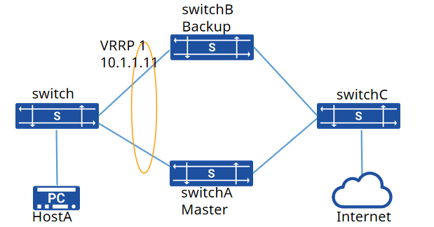
Section titled “Configuration Example”Network Requirements
Host A is dual-homed to Switch A and Switch B. To ensure uninterrupted network transmission for various user services, VRRP master/backup functionality needs to be configured on Switch A and Switch B. Under normal circumstances, hosts access the Internet using Switch A as the default gateway. When Switch A fails, Switch B takes over as the gateway to continue working, providing gateway backup.
Procedure
- Assign each interface of the devices to VLANs and configure IP addresses # switchA
sonic(config)# vlan 10sonic(config)# interface ethernet 49sonic(config-if-49)# switchport access vlan 10sonic(config)# interface ethernet 50sonic(config-if-50)# switchport access vlan 10#switch B
sonic(config)# vlan 10sonic(config)# vlan 20sonic(config)# interface ethernet 1sonic(config-if-1)# switchport access vlan 20sonic(config)# interface ethernet 14sonic(config-if-14)# switchport access vlan 10sonic(config)# interface vlan 10sonic(config-vlanif-10)# ip address 10.1.1.1/24sonic(config)# interface vlan 20sonic(config-vlanif-20)# ip address 192.168.1.1/24sonic(config)# ip route 172.16.1.0/24 192.168.1.2# switchA
sonic(config)# vlan 10sonic(config)# vlan 30sonic(config)# interface ethernet 3sonic(config-if-3)# switchport access vlan 10sonic(config)# interface ethernet 2sonic(config-if-2)# switchport access vlan 30sonic(config)# interface vlan 10sonic(config-vlanif-10)# ip address 10.1.1.2/24sonic(config)# interface vlan 30sonic(config-vlanif-30)# ip address 192.168.2.1/24sonic(config)# ip route 172.16.1.0/24 192.168.2.2# switch C
sonic(config)# vlan 20sonic(config)# vlan 30sonic(config)# vlan 40sonic(config)# interface ethernet 3sonic(config-if-3)# switchport access vlan 30sonic(config)# interface ethernet 2sonic(config-if-2)# switchport access vlan 20sonic(config)# interface ethernet 5sonic(config-if-2)# switchport access vlan 40sonic(config)# interface vlan 20sonic(config-vlanif-20)# ip address 192.168.1.2/24sonic(config)# interface vlan 30sonic(config-vlanif-30)# ip address 192.168.2.2/24sonic(config)# interface vlan 40sonic(config-vlanif-40)# ip address 172.16.1.1/24sonic(config)# ip route 10.1.1.0/24 192.168.1.1sonic(config)# ip route 10.1.1.0/24 192.168.2.1- Configuring VRRP # switchA
sonic(config)# interface vlan 10sonic(config-vlanif-10)# vrrp 1sonic(config-vlanif-10)# vrrp 1 priority 150sonic(config-vlanif-10)# vrrp 1 advertisement-interval 1500sonic(config-vlanif-10)# vrrp 1 ip 10.1.1.11# switch B
sonic(config)# interface vlan 10sonic(config-vlanif-10)# vrrp 1sonic(config-vlanif-10)# vrrp 1 advertisement-interval 1500sonic(config-vlanif-10)# vrrp 1 ip 10.1.1.11Verify configuration
- Ensure that the VRRP status shows Switch A as the master device and Switch B as the backup device.
switchA(config)# show vrrp summaryInterface VRID Priority IPv4 IPv6 State (v4) State (v6)---------------------------------------------------------------------- Vlan10 1 150 1 0 Master Backup- To simulate Switch A failure, you can administratively shut down its interfaces or power off the switch. After Switch A is down, verify the VRRP status on Switch B to ensure it becomes the master device:
switchB(config)# show vrrp summaryInterface VRID Priority IPv4 IPv6 State (v4) State (v6)---------------------------------------------------------------------- Vlan10 1 100 1 0 Master BackupEnsure that Switch B is now the master device. Also, monitor the traffic flow from Host A to the Internet to ensure it continues uninterrupted. If the VRRP failover is successful, Host A should seamlessly communicate with the Internet via Switch B acting as the new master device.