
PTP Configuration
PTP Configuration
Section titled “PTP Configuration”Introduction
Section titled “Introduction”The Precision Time Protocol (PTP) is a protocol used to achieve high-precision clock synchronization in computer networks. It was originally designed to meet the high-precision time requirements of applications in industrial automation, communications, finance, and other fields.
The main goal of PTP is to provide microsecond-level or even sub-microsecond-level clock synchronization accuracy in computer networks. This high level of precision is crucial for many fields, such as high-frequency trading systems, power system synchronization, and the time calibration of scientific research equipment.
Explanation of Principles
Section titled “Explanation of Principles”Basic Concepts of PTP
Section titled “Basic Concepts of PTP”PTP Domain: A PTP domain refers to a logical set of one or more PTP clock nodes that work in the same PTP network and share the same clock synchronization standards and configurations. Within a PTP domain, there is typically one master clock and multiple slave clocks.
Clock Node Types: Nodes in the PTP domain are called clock nodes and the following three types of basic clock nodes are defined in the IEEE 1588 v2 standard:
OC (Ordinary Clock): In the same PTP domain, there is only a single physical port involved in PTP time synchronization. The device uses this port to synchronize time from upstream nodes or to publish time to downstream nodes.
BC (Boundary Clock): In the same PTP domain, at least two or more physical ports can participate in PTP time synchronization. One port synchronizes time from upstream devices, while the remaining ports publish time to downstream devices.
TC (Transparent Clock): The main difference between a TC and BC/OC is that BC and OC need to maintain time synchronization with other devices, while a TC does not. A TC has multiple PTP ports and only forwards PTP messages between these ports, correcting the forwarding delay without synchronizing time from any port.
The following four types of basic clock nodes are defined in the ITU-T G.8275.1 standard:
T-GM (Telecom Grandmaster): This clock node has one or more physical ports involved in time synchronization within the same PTP domain and can only act as a Master, publishing time to downstream clock nodes.
T-BC (Telecom Boundary Clock): This clock node has multiple physical ports involved in time synchronization within the same PTP domain. it synchronizes the time from the upstream clock node through one of the interfaces and publishes the time to the downstream clock nodes through the remaining ports.
T-TSC (Telecom Time Slave Clock): This clock node has only a physical port in the same PTP domain to participate in time synchronization, and can only be used as a Slave to synchronize time from the upstream clock node.
T-TC (Telecom Transparent Clock): This clock node is an End-to-End Transparent Clock (E2E-TC) as defined in [IEEE 1588] and forwards all PTP protocol messages.
The following three types of basic clock nodes are defined in the ITU-T G.8275.2 standard:
T-GM (Telecom Grandmaster): This clock node has one or more physical ports involved in time synchronization within the same PTP domain, and can only act as a Master, publishing time to downstream clock nodes.
T-BC-P (Partial-Support Telecom Boundary Clock): This clock node has multiple physical ports involved in time synchronization within the same PTP domain, and it synchronizes the time from the upstream clock node through one of the interfaces and publishes the time to the downstream clock node through the remaining ports.
T-TSC-P (Partial-Support Telecom Time Slave Clock): This clock node can enable multiple physical ports in the same PTP domain, but it can only act as Slave to synchronize the time from the upstream clock node through one port, while the other ports act as Passive and do not participate in time synchronization.
PTP Ports: Ports on a device running the PTP protocol are known as PTP ports. These ports can be categorized based on their roles:
Master port: A port that publishes synchronized time.
Slave port: A port that receives synchronized time.
Passive port: A port that neither receive nor publish synchronized time.
Establishing Master-Slave Relationships
Section titled “Establishing Master-Slave Relationships”In a PTP domain, node devices synchronize clocks according to a master-slave relationship. The master-slave relationship is relative: the node device that synchronizes time is called a slave node, and the node device that publishes the time is called a master node. A single device might synchronize time from an upstream node while also publishing time to downstream nodes.
For a pair of clock nodes that synchronize with each other, the following master-slave relationships apply:
Master Node: The node that publishes the synchronized time.
Slave Node: The node that receives the synchronized time.
Master Clock: The clock on the master node.
Slave Clock: The clock on the slave node.
Master Port: The port that publishes the synchronized time.
Slave Port: The port that receives the synchronized time.
Grandmaster Clock Selection
Section titled “Grandmaster Clock Selection”Grandmaster clock selection for 1588v2, smpte and aes67
According to the IEEE 1588 v2 protocol standard, each clock node in the PTP domain elects the grandmaster clock through the BMC algorithm, and each clock node sends Announce messages to each other, and finally elects the optimal clock in the domain according to the clock priority, class, accuracy and other information carried in the message. The specific comparison rules are as follows:
- priority1: The smaller the priority1 value, the higher the priority.
- class: If priority1 values are the same, the smaller the class value, the higher the priority.
- accuracy: If the class value is also the same, the smaller the accuracy value, the higher the priority.
- priority2: If the accuracy value is also the same, the smaller the priority2 value, the higher the priority.
Grandmaster clock selection priority: priority1 > class > accuracy > priority2.
According to the ITU-T G.8275.x protocol standard, each clock node in the PTP domain elects the grandmaster clock through the ABMC algorithm, which will compare the clocks in the order of the class, accuracy, priority2 and priority carried by the Announce message, and the winner will be the optimal clock. In this algorithm, multiple GM clocks are allowed to be the grandmaster clock at the same time, when each non-GM clock is synchronized by one of the GMs in the PTP domain, and the comparison rules are as follows:
- class: The smaller the class value, the higher the priority.
- accuracy: If the class values are the same, the smaller the accuracy value, the higher the priority.
- priority2: If the accuracy value is also the same, the smaller the priority2 value, the higher the priority.
- priority: If the priority2 value is also the same, the lower the priority value, the higher the priority.
- If the local priority is still the same, determine if the class is less than or equal to 127.
If the class is less than or equal to 127, in the absence of a better clock node, two or more grandmaster clocks are elected in the PTP domain, and the slave node selects a grandmaster clock as the master node, and forms two spanning trees, and the two spanning trees do not interact with each other in terms of PTP messages.
If the class is greater than 127, the smaller clockID (which consists of the clock number and interface number together) wins.
Grandmaster clock selection priority: class > accuracy> priority2> priority.
When the grandmaster clock in the PTP domain is selected and the master-slave relationship is determined, in the subsequent time synchronization process, if the slave clock does not receive the Announce message sent by the master clock for a certain period of time, the election of the grandmaster clock will be restarted.
Time Synchronization Method
Section titled “Time Synchronization Method”After determining the master-slave relationship between clocks, the master and slave clocks exchange synchronization messages and record the time. By calculating the round-trip time of the messages, the total round-trip delay between the master and slave clocks is computed. If the transmission delays in both directions are the same, half of the total round-trip delay is the one-way delay, which is the clock offset between the master and slave clocks. The slave clock adjusts its local time based on this offset to synchronize with the master clock.
PTP protocol defines two transmission delay measurement mechanisms: Request-Response (E2E) and Peer Delay (P2P) mechanisms. Both mechanisms assume network symmetry.
Request-Response Mechanism (E2E)
Based on whether a Follow_Up message needs to be sent, the request-response mechanism is divided into two modes: two-step mode and one-step mode:
Two-step mode: The transmission timestamp t1 of the Sync message is carried by the Follow_Up message.
One-step mode: The transmission timestamp t1 of the Sync message is carried by the Sync message itself, and no Follow_Up message is sent.
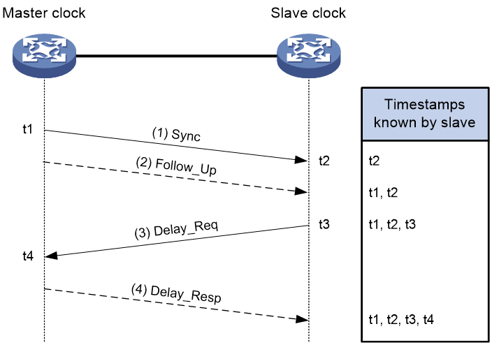
The implementation of the request-response mechanism in two-step mode is as follows:
The master clock sends a Sync message and records the transmission time t1. The slave clock receives this message and records the reception time t2.
After sending the Sync message, the master clock immediately sends a Follow_Up message containing t1.
The slave clock sends a Delay_Req message to the master clock to initiate the calculation of the reverse transmission delay and records the transmission time t3. The master clock receives this message and records the reception time t4.
Upon receiving the Delay_Req message, the master clock responds with a Delay_Resp message containing t4.
Now the slave clock has four timestamps: t1, t2, t3, and t4. The calculations are as follows:
Total Round-Trip Delay = (t2 – t1) + (t4 – t3)
One-Way Delay = [(t2 – t1) + (t4 – t3)] / 2
Clock Offset (Slave relative to Master) Offset = (t2 – t1) – [(t2 – t1) + (t4 – t3)] / 2 = [(t2 – t1) – (t4 – t3) ] / 2
Peer Delay Mechanism (P2P)
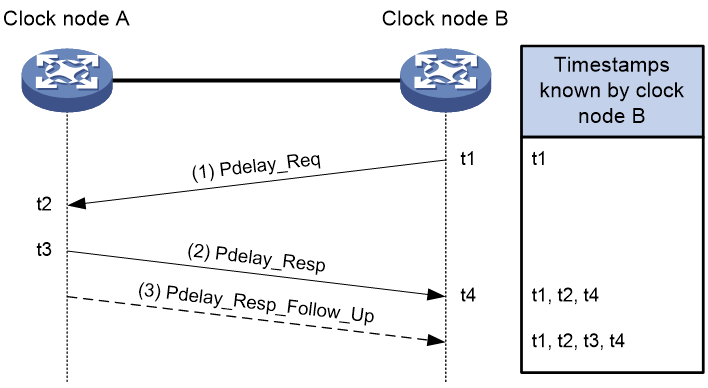
The Peer Delay (P2P) mechanism in PTP is used to calculate the average path delay between two clock nodes. It involves each clock node sending Pdelay messages to each other and calculating the one-way delay for the path between them. If there are Transparent Clocks (TC) between the master and slave clocks, they segment the synchronization path into multiple segments and participate in calculating the delay for each segment. Here’s how the two-step Peer Delay mechanism (P2P) works:
- Pdelay_Req Message Transmission:
Clock node B sends a Pdelay_Req message to Clock node A to initiate the calculation of the reverse transmission delay and records the transmission time t1.
Clock node A receives the Pdelay_Req message and records the reception time t2.
- Pdelay_Resp Message Transmission:
Upon receiving the Pdelay_Req message, Clock node A responds with a Pdelay_Resp message containing t2 and records the transmission time t3.
Clock node B receives the Pdelay_Resp message and records the reception time t4.
- Pdelay_Resp_Follow_Up Message Transmission:
After sending the Pdelay_Resp message, Clock node A immediately sends a Pdelay_Resp_Follow_Up message containing t3.
- Delay Calculation:
Clock node B now has timestamps t1, t2, t3, and t4. Using these timestamps, it calculates:
Round-trip delay between Clock node A and Clock node B: (t2−t1)+(t4−t3)
One-way delay for the link between Clock node A and Clock node B (assuming symmetric network): [(t2−t1)+(t4−t3)]/2=[(t3−t2)+(t4−t1)]/2
Clock node B’s offset relative to Clock node A’s time: Received time of Sync message by Clock node B −Sent time of Sync message by Clock node A – Cumulative one-way delay for each segment of the link – Sum of all TC residence times
PTP Configuration
Section titled “PTP Configuration”Configuring PTP Instance
Section titled “Configuring PTP Instance”Multiple mutually isolated PTP domains can be run on the same physical device, and one instance corresponds to one PTP domain, which ensures that different instances do not interfere with each other, so that different services can be carried out in different PTP domains. Currently, the 102S series devices support the configuration of four PTP domains, and other device types support two PTP domains.
| Operation | Command | Description |
|---|---|---|
| Enter the system configuration view | configure terminal | |
| Configure PTP instance | ptp instance domain-id |
Configuring PTP Profile
Section titled “Configuring PTP Profile”After configuring the switching proflie, the PTP-related configuration of the instance will be deleted, and the PTP configuration will not be deleted if the same profile is configured repeatedly.
| Operation | Command | Description |
|---|---|---|
| Enter the PTP configuration view | ptp instance domain-id | |
| Configure PTP profile | ptp profile {smpte-2059-2|g8275.1|g8275.2|1588v2|aes67} |
Configuring Clock Type
Section titled “Configuring Clock Type”When using the SMPTE-2059-2, 1588v2, and AES67 profiles, the clock types are: OC/BC/TC;
When using the G8275.1 profile, the clock types are: T-GM/T-BC/T-TSC/T-TC;
When using the G8275.2 profile, the clock types are: T-GM/T-BC-P/T-TSC-P.
| Operation | Command | Description |
|---|---|---|
| Enter the PTP configuration view | ptp instance domain-id | |
| Configure PTP clock type | ptp clock-type {oc|bc|tc|t-gm|t-bc|t-tsc|t-tc|t-bc-p|t-tsc-p} | oc: Ordinary Clock bc: Boundary Clock tc: Transparent Clock t-gm: Telecom Grandmaster t-bc: Telecom Boundary Clock t-tc: Telecom Transparent Clock t-tsc: Telecom Time Slave Clock t-bc-p: Partial-Support Telecom Boundary Clock t-tsc-p: Partial-Support Telecom Time Slave Clock |
Configuring clock-source Parameters
Section titled “Configuring clock-source Parameters”The master-slave relationship between clock nodes is determined by configuring the clock source parameters for each node.
priority1 can only be configured when the profile is set to smpte-2059-2, 1588v2, or aes67.
priority can only be configured in the interface view when the profile is set to g8275.1 or g8275.2.
priority2/class/accuracy can be configured under all profiles.
When the clock source is configured as GNSS, class/accuracy cannot be manually configured and will be dynamically adjusted based on the GNSS status; the device’s default clock source is local.
Only the CX308P-48S device supports configuring the clock source as GNSS.
| Operation | Command | Description |
|---|---|---|
| Enter the PTP configuration view | ptp instance domain-id | |
| Configuring Clock Source Parameters | ptpclock-source {accuracy| class|priority1|priority2|gnss|local} | accuracy: Configurable range 0-255, default value 254 class: Configurable range 0-255, default value 248 priority1: Configurable range 0-255, default value 128 priority2: Configurable range 0-255, default value 128 gnss: Set the device clock source to “GNSS” local: Set the device clock source to “local” |
| Enter the interface configuration view | interface ethernet interface-id | |
| Enter the PTP interface configuration view | ptpinstance instance-id | Required |
| Configure the interface clock source parameters | ptp local priority | priority: Configurable range 1-255, default value 128 |
Configuring PTP Interface Mode
Section titled “Configuring PTP Interface Mode”When the mode of the PTP interface is not configured, the interface mode will be elected as master, slave, or passive during clock election.
when the PTP interface mode is manually specified, if the current device interface is master, the priority of the device’s clock-source local parameter must be greater than that of the peer; if the current device interface is slave, the priority of the device’s clock-source local parameter must be less than that of the peer.
When a slave device has multiple PTP interfaces all elected as slave mode, only one PTP interface of this device will be in slave mode, and the remaining interfaces will all be in passive mode.
| Operation | Command | Description |
|---|---|---|
| Enter the PTP interface configuration view | ptp instance domain-id | |
| interface ethernet interface_num | ||
| Configure PTP interface mode | ptp mode {master|slave} |
Configuring Delay Measurement Mechanism
Section titled “Configuring Delay Measurement Mechanism”The E2E delay measurement mechanism is used by default.
The P2P delay measurement mechanism is only supported to be configured when the PTP profile is smpte-2059-2, 1588v2 or aes67.
The P2P+one_step configuration scenario is not supported.
| Operation | Command | Description |
|---|---|---|
| Enter the PTP configuration view | ptp instance domain-id | |
| Configure delay measurement mechanism | ptp delay-mode {E2E|P2P} |
Configuring Timestamp Carrying Mode
Section titled “Configuring Timestamp Carrying Mode”PTP records the timestamps generated by the event message interaction between the master and slave clocks, calculates the path delay and time deviation between the master and slave clocks, and achieves time and frequency synchronization. The timestamp carrying mode is divided into the following two types:
Single-step mode (one_step): The master clock sends out the packets that need to be timestamped directly. For example, when the master clock sends a Sync message, the hardware chip marks t1 and puts it in the timestamp field of the Sync message and sends it directly. There is no need to send a FollowUp message subsequently.
Two-step mode (two_step): Marking the timestamp and sending the message are completed by two-step messages. For example, the timestamp t1 generated by the master clock sending the Sync synchronization message is marked and stored by the hardware chip. When the FollowUp message is sent, it is carried and sent to the slave clock.
| Operation | Command | Description |
|---|---|---|
| Enter the PTP configuration view | ptp instance domain-id | |
| Configure timestamp carrying mode | ptp clock-step {two_step|one_step} | When profile is 1588v2, two_step is used by default, and one_step is used by default when using other profiles |
Configuring Transport Mode
Section titled “Configuring Transport Mode”If unicast communication is used between clock nodes, configure the destination IP address of the unicast PTP message to be the IP address of the peer PTP interface.
If multicast or mixed communication is used between clock nodes, configure the interface address as the source IP address of the PTP message.
When the profile is smpte-2059-2, UDPv4/UDPv6 unicast, multicast, and mixed transport modes are supported.
When the profile is 1588v2, UDPv4/UDPv6 unicast, multicast, and Ethernet transport modes are supported. Additionally, when switching from UDPv4/UDPv6 unicast to Ethernet, the interface’s unicast master address A.B.C.D/A::B must be deleted.
When the profile is G8275.1, only Ethernet transport mode is supported.
When the profile is G8275.2/SMPTE/AES67, Ethernet transport mode is not supported.
When the profile is AES67, Ethernet and UDPv6 transport modes are not supported.
| Operation | Command | Description |
|---|---|---|
| Enter the PTP configuration view | ptp instance domain-id | |
| Configure transport mode | ptp transport-mode {udpv4|udpv6|ethernet} [unicast|multicast|mixed] |
Configuring the PTP Message Sending Interval
Section titled “Configuring the PTP Message Sending Interval”Currently, it can support modifying the Sync, Announce, Delay_Req, and Pdelay_Req message sending interval, and the actual effective value is the logarithm of the time interval in seconds with 2 as the base. For example, if the parameter value is -2, the time interval is 0.25 seconds; if the parameter value is -1, the time interval is 0.5 seconds. For fast synchronization, it is recommended to use the default value or a shorter interval than the default value.
| Operation | Command | Description |
|---|---|---|
| Enter the PTP interface configuration view | interface ethernet interface_num ptp instance domain-id | |
| Configure the Sync message sending interval | ptp sync-interval interval | When the ptp profile is smpte-2059-2, the interval setting of this parameter ranges from -7 to 1, and the default value is -3 When the ptp profile is g8275.2, the parameter interval setting ranges from -7 to 0, and the default value is -4 When the ptp profile is g8275.1, the default value of this parameter interval is -4, and does not support modification When the ptp profile is 1588v2, the interval of this parameter is set from -7 to 1, and the default value is 0 When the ptp profile is aes67, the interval of this parameter is set from -4 to 1, and the default value is -3 |
| Configure the Announce message sending interval | ptp announce-interval interval | When the ptp profile is smpte-2059-2, the interval setting of this parameter ranges from -3 to 1, and the default value is 0 When the ptp profile is g8275.2, the parameter interval setting ranges from -3 to 0, and the default value is -3 When the ptp profile is g8275.1, the default value of this parameter interval is -3, and does not support modification When the ptp profile is 1588v2, the interval of this parameter is set from 0 to 4, and the default value is 1 When the ptp profile is aes67, the interval of this parameter is set from 0 to 4, and the default value is 1 |
| Configure the Delay_Req message sending interval | ptp delay-req-interval interval | When the ptp profile is smpte-2059-2, the interval setting of this parameter ranges from -3 to 5, and the default value is -3 When the ptp profile is g8275.2, the parameter interval setting ranges from -7 to 0, and the default value is -4 When the ptp profile is g8275.1, the default value of this parameter interval is -4, and does not support modification When the ptp profile is 1588v2, the interval of this parameter is set from -7 to 5, and the default value is 0 When the ptp profile is aes67, the interval of this parameter is set from -4 to 5, and the default value is 0 |
| Configure the Pdelay_Req message sending interval | ptp pdelay-req-interval interval | When the ptp profile is smpte-2059-2, the interval setting of this parameter ranges from -3 to 5, and the default value is -3. When the ptp profile is 1588v2, the interval setting of this parameter ranges from -7 to 5, and the default value is 0. When the ptp profile is aes67, the interval setting of this parameter ranges from -4 to 5, and the default value is 0. |
SM-TLV Configuration
Section titled “SM-TLV Configuration”In the SMPTE 2059-2 standard, SM-TLV (Stream Mapping Type-Length-Value) is a format for transmitting timecode and synchronization information to convey and manage time synchronization information in multi-device and multi-system environments to ensure accurate synchronization between devices. Therefore this function can only be used when the ptp profile is smpte.
Enable SM-TLV
Section titled “Enable SM-TLV”When sm-tlv is enabled, Daylight Saving Time events are supported on the device. The BC clock receives the Daylight Saving Time message, records the jump time, prepares for the jump in advance, processes the jump when the seconds arrive, and forwards the message to the OC Clock. so that the system clock jumps forward or backward by one hour at the beginning and end of Daylight Saving Time, which prevents the inconsistency in time synchronization caused by such time jumps. (Daylight Saving Time (DST) is a system that artificially defines the local time in order to save energy,and the uniform time used during the implementation of this system is called “Daylight Saving Time”.)
| Operation | Command | Description |
|---|---|---|
| Enter the system configuration view | configure terminal | |
| Enable sm-tlv | ptp sm-tlv enable |
Configuring default-frame-rates
Section titled “Configuring default-frame-rates”This configuration is used on the master clock, which affects the synchronization of all devices through the time base it provides; the BC, as a relay device, will be responsible for forwarding sm-tlv information to ensure the smooth flow of data throughout the PTP domain; the OC receives the sm-tlv data and applies the timecode and synchronization information in it to maintain synchronization with the PTP domain.
| Operation | Command | Description |
|---|---|---|
| Enter the system configuration view | configure terminal | |
| Configure default frame rate | ptp sm-tlv default-frame-rates numerator denominator | The numerator/denominator is the effective frame rate. |
Display and Maintenance
Section titled “Display and Maintenance”| Operation | Command |
|---|---|
| Display PTP synchronization status | show ptp clock |
| Display PTP interface status | show ptp interface interface_num |
| Display sm-tlv status | show ptp clock sm-tlv domain-id |
| Display PTP message statistics | show ptp counter [interface id ] [instance domain_id ] |
PTP Configuration Example
Section titled “PTP Configuration Example”Using Smpte for IPv4 UDP Encapsulated and Multicast Communication
Section titled “Using Smpte for IPv4 UDP Encapsulated and Multicast Communication”Network requirements
In this networking, Device A and Device B are in the same PTP domain, using the smpte-2059-2 protocol standard and IPv4 UDP encapsulated multicast communication. Device A is used as the grandmaster clock. PTP synchronization from Device B to Device A is achieved using the P2P delay measurement mechanism and two_step timestamp carrying mode.

Procedur
# Device A
sonic(config)# ptp enablesonic(config)# ptp instance 0sonic(config-ptp-0)# ptp profile smpte-2059-2sonic(config-ptp-0)# ptp clock-id 000217.0000.000023sonic(config-ptp-0)# ptp enablesonic(config-ptp-0)# ptp clock-type ocsonic(config-ptp-0)# ptp delay-mode P2Psonic(config-ptp-0)# ptp clock-source local priority1 64sonic(config-ptp-0)# ptp clock-step two_stepsonic(config-ptp-0)# ptp transport-mode udpv4 multicastsonic(config)# interface ethernet 1sonic(config-if-1)# ip address 10.1.1.1/24sonic(config-if-1)# ptp instance 0sonic(config-if-ptp-0)# ptp enablesonic(config-if-ptp-0)# ptp source ip 10.1.1.1# Device B
sonic(config)# ptp enablesonic(config)# ptp instance 0sonic(config-ptp-0)# ptp profile smpte-2059-2sonic(config-ptp-0)# ptp clock-id 000224.0000.000023sonic(config-ptp-0)# ptp clock-type ocsonic(config-ptp-0)# ptp delay-mode P2Psonic(config-ptp-0)# ptp clock-source local priority1 128sonic(config-ptp-0)# ptp clock-step two_stepsonic(config-ptp-0)# ptp transport-mode udpv4 multicastsonic(config)# interface ethernet 1sonic(config-if-1)# ptp instance 0sonic(config-if-ptp-0)# ptp enablesonic(config-if-ptp-0)# ptp source ip 10.1.1.2Verify configuration
# Display PTP synchronization status on Device B
Domain: 0Profile: smpte-2059-2Clock Type: OCClock Step: two_stepDelay Mode: P2PTransport Mode: udpv4Dscp: 56Source IP Address: 0.0.0.0Local Clock Identity: 000224.0000.000023Local Clock Accuracy: 0xFELocal Clock Class: 248Local Clock Priority1: 128Local Clock Priority2: 128ports: Ethernet23Grandmaster Clock Identity: 000217.0000.000023Grandmaster Clock Accuracy: 0xfeGrandmaster Clock Class: 248Grandmaster Clock Priority1: 64Grandmaster Clock Priority2: 128Parent Port Identity: 0Servo State: lockedOffset To Master: -12Path Delay: 239Max Steps Removed: 255Local Time: 432962822290957# Display PTP interface 1 status on Device B
sonic# show ptp interface 1Ethernet: Ethernet1Enable: trueDomain: 0Index: 1Source IP Address: 10.1.1.2Announce Interval: 0Announce Receipt Timeout: 3Delay Req Interval: -3Pdelay Req Interval: -3Sync Interval: -3Mode: slaveDelay Mode: P2PUsing Smpte for IPv4 UDP Encapsulated and Unicast Communication
Section titled “Using Smpte for IPv4 UDP Encapsulated and Unicast Communication”Network requirements
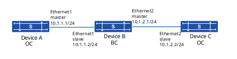
In this networking, Device A, Device B and Device C are in the same PTP domain, using the smpte-2059-2 protocol standard and IPv4 UDP encapsulated unicast communication. Using Device A as the grandmaster clock, the PTP synchronization of Device B and Device C to Device A is achieved using the E2E delay measurement mechanism and the timestamp carrying mode of two_step.
Procedur
# Device A
sonic(config)# ptp enablesonic(config)# ptp instance 0sonic(config-ptp-0)# ptp profile smpte-2059-2sonic(config-ptp-0)# ptp clock-type ocsonic(config-ptp-0)# ptp clock-source local priority1 64sonic(config-ptp-0)# ptp clock-step two_stepsonic(config-ptp-0)# ptp transport-mode udpv4 unicastsonic(config)# interface ethernet 1sonic(config-if-1)# ip address 10.1.1.1/24sonic(config-if-1)# ptp instance 0sonic(config-if-ptp-0)# ptp enablesonic(config-if-ptp-0)# ptp source ip 10.1.1.1# Device B
sonic(config)# ptp enablesonic(config)# ptp instance 0sonic(config-ptp-0)# ptp profile smpte-2059-2sonic(config-ptp-0)# ptp clock-type bcsonic(config-ptp-0)# ptp clock-source local priority1 127sonic(config-ptp-0)# ptp clock-step two_stepsonic(config-ptp-0)# ptp transport-mode udpv4 unicastsonic(config)# interface ethernet 1sonic(config-if-1)# ip address 10.1.1.2/24sonic(config-if-1)# ptp instance 0sonic(config-if-ptp-0)# ptp enablesonic(config-if-ptp-0)# ptp unicast master address 10.1.1.1sonic(config-if-ptp-0)# ptp source ip 10.1.1.2sonic(config)# interface ethernet 2sonic(config-if-2)# ip address 10.1.2.1/24sonic(config-if-2)# ptp instance 0sonic(config-if-ptp-0)# ptp enablesonic(config-if-ptp-0)# ptp source ip 10.1.2.1# Device C
sonic(config)# ptp enablesonic(config)# ptp instance 0sonic(config-ptp-0)# ptp profile smpte-2059-2sonic(config-ptp-0)# ptp clock-type ocsonic(config-ptp-0)# ptp clock-source local priority1 255sonic(config-ptp-0)# ptp clock-step two_stepsonic(config-ptp-0)# ptp transport-mode udpv4 unicastsonic(config)# interface ethernet 2sonic(config-if-2)# ip address 10.1.2.2/24sonic(config-if-2)# ptp instance 0sonic(config-if-ptp-0)# ptp enablesonic(config-if-ptp-0)# ptp source ip 10.1.2.2sonic(config-if-ptp-0)# ptp unicast master address 10.1.2.1Verify configuration
# Display PTP synchronization status on Device B
sonic# show ptp clockDomain: 127Profile: smpte-2059-2Clock Type: BCClock step: two_stepDelay Mode: E2ETransport Mode: udpv4Dscp: 56Source IP Address: 0.0.0.0Local Clock Identity: 000FE2.FFFE.FF0000Local Clock Accuracy: 0xFELocal Clock Class: 248Local Clock Priority1: 127Local Clock Priority2: 128ports: Ethernet1,Ethernet2Grandmaster Clock Identity: 60eb5a.fffe.010299Grandmaster Clock Accuracy: 0xFEGrandmaster Clock Class: 248Grandmaster Priority1: 64Grandmaster Priority2: 128Parent Port Identity: 1Servo_state: lockedOffset_to_master: 10Path delay: 268Max Steps Removed: 255Local Time: 86235188577296# Display PTP interface 1 status on Device B
sonic# show ptp interface 1Ethernet: Ethernet1Enable: trueDomain: 0Index: 1Dscp: 56Source IP Address: 10.1.1.2Announce Interval: 0Announce Receipt Timeout: 3Delay Req Interval: -3Pdelay Req Interval: -3Sync Interval: -3Mode: slaveDelay Mode: E2EUnicat Master Address: ['10.1.1.1']# Display PTP interface 2 status on Device B
sonic# show ptp interface 2Ethernet: Ethernet2Enable: trueDomain: 0Index: 2Dscp: 56Source IP Address: 10.1.2.1Announce Interval: 0Announce Receipt Timeout: 3Delay Req Interval: -3Pdelay Req Interval: -3Sync Interval: -3Mode: masterDelay Mode: E2E# Display PTP synchronization status on Device C
sonic# show ptp clockDomain: 127Profile: smpte-2059-2Clock Type: OCClock step: two_stepDelay Mode: E2ETransport Mode: udpv4Dscp: 56Source IP Address: 0.0.0.0Local Clock Identity: 100520.2542.551384Local Clock Accuracy: 0xFELocal Clock Class: 248Local Clock Priority1: 255Local Clock Priority2: 128ports: Ethernet2Grandmaster Clock Identity: 60eb5a.fffe.010299Grandmaster Clock Accuracy: 0xFEGrandmaster Clock Class: 248Grandmaster Priority1: 64Grandmaster Priority2: 128Parent Port Identity: 2Servo_state: lockedOffset_to_master: 17Path delay: 566Max Steps Removed: 255Local Time: 86235462577461Using smpte for IPv4 UDP Encapsulated and Mixed Communication
Section titled “Using smpte for IPv4 UDP Encapsulated and Mixed Communication”Network requirements
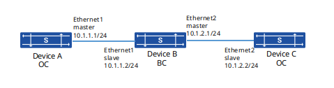
In this networking, Device A, Device B and Device C are in the same PTP domain and use the smpte-2059-2 protocol standard as well as IPv4 UDP encapsulation mixed communication. Device A is used as the grandmaster, and the E2E delay measurement mechanism and one_step timestamp carrying mode are used to realize the PTP synchronization from Device B and Device C to Device A.
Procedure
# Device A
sonic(config)# ptp enablesonic(config)# ptp instance 0sonic(config-ptp-0)# ptp profile smpte-2059-2sonic(config-ptp-0)# ptp clock-type ocsonic(config-ptp-0)# ptp clock-source local priority1 64sonic(config-ptp-0)# ptp transport-mode udpv4 mixedsonic(config)# interface ethernet 1sonic(config-if-1)# ip address 10.1.1.1/24sonic(config-if-1)# ptp instance 0sonic(config-if-ptp-0)# ptp enablesonic(config-if-ptp-0)# ptp source ip 10.1.1.1# Device B
sonic(config)# ptp enablesonic(config)# ptp instance 0sonic(config-ptp-0)# ptp profile smpte-2059-2sonic(config-ptp-0)# ptp clock-type bcsonic(config-ptp-0)# ptp clock-source local priority1 127sonic(config-ptp-0)# ptp transport-mode udpv4 mixedsonic(config)# interface ethernet 1sonic(config-if-1)# ip address 10.1.1.2/24sonic(config-if-1)# ptp instance 0sonic(config-if-ptp-0)# ptp enablesonic(config-if-ptp-0)# ptp source ip 10.1.1.2sonic(config)# interface ethernet 2sonic(config-if-2)# ip address 10.1.2.1/24sonic(config-if-2)# ptp instance 0sonic(config-if-ptp-0)# ptp enablesonic(config-if-ptp-0)# ptp source ip 10.1.2.1# Device C
sonic(config)# ptp enablesonic(config)# ptp instance 0sonic(config-ptp-0)# ptp profile smpte-2059-2sonic(config-ptp-0)# ptp clock-type ocsonic(config-ptp-0)# ptp clock-source local priority1 255sonic(config-ptp-0)# ptp transport-mode udpv4 mixedsonic(config)# interface ethernet 2sonic(config-if-2)# ip address 10.1.2.2/24sonic(config-if-2)# ptp instance 0sonic(config-if-ptp-0)# ptp enablesonic(config-if-ptp-0)# ptp source ip 10.1.2.2Verify configuration
# Display PTP synchronization status on Device B
sonic# show ptp clockDomain: 127Profile: smpte-2059-2Clock Type: BCClock step: one_stepDelay Mode: E2ETransport Mode: udpv4Dscp: 56Source IP Address: 0.0.0.0Local Clock Identity: 000FE2.FFFE.FF0000Local Clock Accuracy: 0xFELocal Clock Class: 128Local Clock Priority1: 127Local Clock Priority2: 128ports: Ethernet1,Ethernet2Grandmaster Clock Identity: 60eb5a.fffe.010299Grandmaster Clock Accuracy: 0xFEGrandmaster Clock Class: 128Grandmaster Priority1: 64Grandmaster Priority2: 128Parent Port Identity: 1Servo_state: lockedOffset_to_master: 10Path delay: 268Max Steps Removed: 255Local Time: 86235188577296# Display PTP interface 1 status on Device B
sonic# show ptp interface 1Ethernet: Ethernet1Enable: trueDomain: 0Index: 1Source IP Address: 10.1.1.2Announce Interval: 0Announce Receipt Timeout: 3Delay Req Interval: -3Pdelay Req Interval: -3Sync Interval: -3Mode: slaveDelay Mode: E2EUnicat Master Address: ['10.1.1.1']# Display PTP interface 2 status on Device B
sonic# show ptp interface 2Ethernet: Ethernet2Enable: trueDomain: 0Index: 2Source IP Address: 10.1.2.1Announce Interval: 0Announce Receipt Timeout: 3Delay Req Interval: -3Pdelay Req Interval: -3Sync Interval: -3Mode: masterDelay Mode: E2E# Display PTP synchronization status on Device C
sonic# show ptp clockDomain: 127Profile: smpte-2059-2Clock Type: OCClock step: one_stepDelay Mode: E2ETransport Mode: udpv4Dscp: 56Source IP Address: 0.0.0.0Local Clock Identity: 100520.2542.551384Local Clock Accuracy: 0xFELocal Clock Class: 128Local Clock Priority1: 255Local Clock Priority2: 128ports: Ethernet2Grandmaster Clock Identity: 60eb5a.fffe.010299Grandmaster Clock Accuracy: 0xFEGrandmaster Clock Class: 128Grandmaster Priority1: 64Grandmaster Priority2: 128Parent Port Identity: 2Servo_state: lockedOffset_to_master: 17Path delay: 539Max Steps Removed: 255Local Time: 86235462577461PTP Multi-Domain Synchronization Example
Section titled “PTP Multi-Domain Synchronization Example”Network requirements
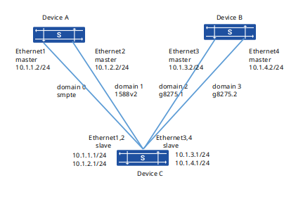
In this network, both Device A and Device B support two PTP domains, and the domain 0 and domain 1 of Device A use the smpte and 1588v2 protocol standards as the master, and the domain 2 and domain 3 of Device B use the g8275.1 and g8275.2 protocol standards as the master. Device C supports four PTP domains and uses domain 0, domain 1, domain 2 and domain 4 to synchronize PTP time to the two domains of Device A and Device B respectively.
Procedure
# Device A
sonic(config)# ptp enable# Configuring PTP domain 0
sonic(config)# ptp instance 0sonic(config-ptp-0)# ptp profile smpte-2059-2sonic(config-ptp-0)# ptp clock-id 000145.0000.440046sonic(config-ptp-0)# ptp clock-type ocsonic(config-ptp-0)# ptp clock-step one_stepsonic(config-ptp-0)# ptp delay-mode E2Esonic(config-ptp-0)# ptp clock-source local priority1 64sonic(config-ptp-0)# ptp transport-mode udpv4 unicast# Configuring PTP domain 1
sonic(config)# ptp instance 1sonic(config-ptp-0)# ptp profile 1588v2sonic(config-ptp-0)# ptp clock-id 000145.0000.450047sonic(config-ptp-0)# ptp clock-type ocsonic(config-ptp-0)# ptp clock-step one_stepsonic(config-ptp-0)# ptp delay-mode E2Esonic(config-ptp-0)# ptp clock-source local priority1 64# Configuring PTP interface
sonic(config)# interface ethernet 1sonic(config-if-1)# ip address 10.1.1.2/24sonic(config-if-1)# ptp instance 0sonic(config-if-ptp-0)# ptp enablesonic(config-if-ptp-0)# ptp source ip 10.1.1.2sonic(config)# interface ethernet 2sonic(config-if-2)# ip address 10.1.2.2/24sonic(config-if-2)# ptp instance 1sonic(config-if-ptp-1)# ptp enablesonic(config-if-ptp-0)# ptp source ip 10.1.2.2# Device B
sonic(config)# ptp enable# Configuring PTP domain 2
sonic(config)# ptp instance 2sonic(config-ptp-0)# ptp profile g8275.1sonic(config-ptp-0)# ptp clock-id 000016.0000.000018sonic(config-ptp-0)# ptp clock-type t-gmsonic(config-ptp-0)# ptp clock-step one_stepsonic(config-ptp-0)# ptp delay-mode E2Esonic(config-ptp-0)# ptp clock-source local priority1 64# Configuring PTP domain 3
sonic(config)# ptp instance 3sonic(config-ptp-0)# ptp profile g8275.2sonic(config-ptp-0)# ptp clock-id 000016.0000.000017sonic(config-ptp-0)# ptp clock-type t-gmsonic(config-ptp-0)# ptp clock-step one_stepsonic(config-ptp-0)# ptp delay-mode E2Esonic(config-ptp-0)# ptp clock-source local priority1 64sonic(config-ptp-0)# ptp transport-mode udpv4 unicast# Configuring PTP interface
sonic(config)# interface ethernet 3sonic(config-if-1)# ip address 10.1.3.2/24sonic(config-if-1)# ptp instance 2sonic(config-if-ptp-2)# ptp enablesonic(config-if-ptp-2)# ptp source ip 10.1.3.2sonic(config)# interface ethernet 4sonic(config-if-2)# ip address 10.1.4.2/24sonic(config-if-2)# ptp instance 3sonic(config-if-ptp-3)# ptp enablesonic(config-if-ptp-3)# ptp source ip 10.1.4.2# Device B
sonic(config)# ptp enable# Configuring PTP domain 0
sonic(config)# ptp instance 0sonic(config-ptp-0)# ptp profile smpte-2059-2sonic(config-ptp-0)# ptp clock-id 000150.0000.000017sonic(config-ptp-0)# ptp clock-type ocsonic(config-ptp-0)# ptp clock-step one_stepsonic(config-ptp-0)# ptp delay-mode E2Esonic(config-ptp-0)# ptp clock-source local priority1 128sonic(config-ptp-0)# ptp transport-mode udpv4 unicast# Configuring PTP domain 1
sonic(config)# ptp instance 1sonic(config-ptp-0)# ptp profile 1588v2sonic(config-ptp-0)# ptp clock-id 000150.0000.000018sonic(config-ptp-0)# ptp clock-type ocsonic(config-ptp-0)# ptp clock-step one_stepsonic(config-ptp-0)# ptp delay-mode E2Esonic(config-ptp-0)# ptp clock-source local priority1 128# Configuring PTP domain 2
sonic(config)# ptp instance 2sonic(config-ptp-0)# ptp profile g8275.1sonic(config-ptp-0)# ptp clock-id 000150.0000.000008sonic(config-ptp-0)# ptp clock-type t-tscsonic(config-ptp-0)# ptp clock-step one_stepsonic(config-ptp-0)# ptp delay-mode E2Esonic(config-ptp-0)# ptp clock-source local priority1 128# Configuring PTP domain 3
sonic(config)# ptp instance 3sonic(config-ptp-0)# ptp profile g8275.2sonic(config-ptp-0)# ptp clock-id 000150.0000.000007sonic(config-ptp-0)# ptp clock-type t-tsc-psonic(config-ptp-0)# ptp clock-step one_stepsonic(config-ptp-0)# ptp delay-mode E2Esonic(config-ptp-0)# ptp clock-source local priority1 128sonic(config-ptp-0)# ptp transport-mode udpv4 unicast# Configuring PTP interface
sonic(config)# interface ethernet 1sonic(config-if-1)# ip address 10.1.1.1/24sonic(config-if-1)# ptp instance 0sonic(config-if-ptp-0)# ptp enablesonic(config-if-ptp-0)# ptp source ip 10.1.1.1sonic(config-if-ptp-0)# ptp unicast master address 10.1.1.2sonic(config)# interface ethernet 2sonic(config-if-2)# ip address 10.1.2.1/24sonic(config-if-2)# ptp instance 1sonic(config-if-ptp-1)# ptp enablesonic(config-if-ptp-1)# ptp source ip 10.1.2.1
sonic(config)# interface ethernet 3sonic(config-if-3)# ip address 10.1.3.1/24sonic(config-if-3)# ptp instance 2sonic(config-if-ptp-2)# ptp enablesonic(config-if-ptp-2)# ptp source ip 10.1.3.1sonic(config)# interface ethernet 4sonic(config-if-4)# ip address 10.1.4.1/24sonic(config-if-4)# ptp instance 3sonic(config-if-ptp-3)# ptp enablesonic(config-if-ptp-3)# ptp source ip 10.1.4.1sonic(config-if-ptp-3)# ptp unicast master address 10.1.4.2
Verify configuration
# Display PTP synchronization status on Device C
sonic# show ptp clockDomain: 1Profile: 1588v2Clock Type: OCClock Step: one_stepDelay Mode: E2ETransport Mode: udpv4Dscp: 56Source IP Address: 0.0.0.0Local Clock Identity: 000150.0000.000018Local Clock Accuracy: 0xFELocal Clock Class: 128Local Clock Priority1: 128Local Clock Priority2: 128ports: Ethernet2Grandmaster Clock Identity: 000145.0000.450047Grandmaster Clock Accuracy: 0xfeGrandmaster Clock Class: 64Grandmaster Clock Priority1: 128Grandmaster Clock Priority2: 128Parent Port Identity: 3Servo State: lockedOffset To Master: 14Path Delay: 328Max Steps Removed: 255Local Time: 12235450387301...Using GNSS smpte for IPv4 UDP Encapsulated and Multicast Communication
Section titled “Using GNSS smpte for IPv4 UDP Encapsulated and Multicast Communication”Network requirements
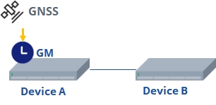
In this networking, Device A and Device B are in the same PTP domain, using the smpte-2059-2 protocol standard and IPv4 UDP encapsulated multicast communication. Device A uses GNSS satellite signals as the clock source. PTP synchronization from Device A to Device B is achieved using the P2P delay measurement mechanism and two_step timestamp carrying mode. Note: Currently, only the CX306P‑48Y device supports GNSS satellite source synchronization.
Procedure
# Device A
sonic(config)# ptp enablesonic(config)# ptp instance 0sonic(config-ptp-0)# ptp profile smpte-2059-2sonic(config-ptp-0)# ptp clock-id 000217.0000.000023sonic(config-ptp-0)# ptp enablesonic(config-ptp-0)# ptp clock-type ocsonic(config-ptp-0)# ptp delay-mode P2Psonic(config-ptp-0)# ptp clock-source priority1 64sonic(config-ptp-0)# ptp clock-step two_stepsonic(config-ptp-0)# ptp transport-mode udpv4 multicastsonic(config-ptp-0)# ptp clock-source gnsssonic(config)# interface ethernet 1sonic(config-if-1)# ip address 10.1.1.1/24sonic(config-if-1)# ptp instance 0sonic(config-if-ptp-0)# ptp enablesonic(config-if-ptp-0)# ptp source ip 10.1.1.1# Device B
sonic(config)# ptp enablesonic(config)# ptp instance 0sonic(config-ptp-0)# ptp profile smpte-2059-2sonic(config-ptp-0)# ptp clock-id 000224.0000.000023sonic(config-ptp-0)# ptp clock-type ocsonic(config-ptp-0)# ptp delay-mode P2Psonic(config-ptp-0)# ptp clock-source priority1 128sonic(config-ptp-0)# ptp clock-step two_stepsonic(config-ptp-0)# ptp transport-mode udpv4 multicastsonic(config)# interface ethernet 1sonic(config-if-1)# ptp instance 0sonic(config-if-ptp-0)# ptp enablesonic(config-if-ptp-0)# ptp source ip 10.1.1.2Verify configuration
# Display PTP synchronization status on Device B
Domain: 0Profile: smpte-2059-2Clock Type: OCClock Step: two_stepDelay Mode: P2PTransport Mode: udpv4Dscp: 56Source IP Address: 0.0.0.0Local Clock Identity: 000224.0000.000023Local Clock Accuracy: 0xFELocal Clock Class: 248Local Clock Priority1: 128Local Clock Priority2: 128ports: Ethernet23Grandmaster Clock Identity: 000217.0000.000023Grandmaster Clock Accuracy: 0xfeGrandmaster Clock Class: 248Grandmaster Clock Priority1: 64Grandmaster Clock Priority2: 128Parent Port Identity: 0Servo State: lockedOffset To Master: -12Path Delay: 239Max Steps Removed: 255Local Time: 432962822290957