
DHCP Server Configuration
Introduction
Section titled “Introduction”The Dynamic Host Configuration Protocol (DHCP) is a technology used for centralized management and configuration of user IP addresses. Following the RFC 2131 standard, DHCP operates in a client/server communication model, where DHCP clients send requests to DHCP servers. These servers allocate IP addresses to clients with a designated usage period known as the lease time.
This allocation mechanism is suitable for scenarios involving hosts that require temporary network access or cases where the total number of network hosts is substantial, and the available addresses are limited. It is especially useful when hosts do not need a permanent network connection.
Explanation of Principles
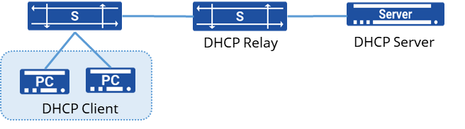
Section titled “Explanation of Principles”A typical DHCP network setup involves three primary roles:
- DHCP Server
The DHCP server is responsible for selecting an IP address from an available address pool and assigning it to a DHCP client. Additionally, it can provide other network parameters such as the default gateway address, DNS server addresses, and WINS server addresses. The DHCP server can handle DHCP request packets within its local subnet as well as DHCP request packets forwarded across subnets through DHCP relays.
- DHCP Client
The DHCP client actively sends DHCP request packets using the BOOTP or DHCP protocol to obtain an IP address and other network parameters. Typical DHCP clients include devices like IP phones, personal computers, mobile phones, diskless workstations, and more.
- DHCP Relay
When a DHCP client broadcasts a request packet, DHCP servers within the same subnet can receive and process these requests. However, if the DHCP client and the DHCP server are not within the same subnet, the DHCP server will not directly receive the client’s request. In such cases, a DHCP relay is used to forward the DHCP packets. Unlike traditional IP packet forwarding, the DHCP relay receives DHCP request or response packets, reconstructs new DHCP unicast packets, and forwards them through the Layer 3 network.
IP Address Acquisition Process
Section titled “IP Address Acquisition Process”The DHCP process involves the following fundamental stages:
- Discovery and Request Stage:
When a device (DHCP client) joins a network or requires reconfiguration of network information, it broadcasts a DHCP Discover message to all devices in the local network. This message is sent to locate available DHCP servers.
- Offer and Selection Stage:
After one or more DHCP servers within the network receive the DHCP Discover message, they respond with a DHCP Offer broadcast message. This message contains available IP addresses, lease durations, subnet masks, default gateways, and other configuration details.
- Request and Acknowledgment Stage:
Upon receiving multiple DHCP Offer messages, the DHCP client typically chooses one of them and sends a DHCP Request broadcast message to the chosen server. This indicates the client’s acceptance of the offered configuration from that specific server.
- Acknowledgment and Lease Stage:
Upon receiving the DHCP Request message from the client, the DHCP server sends a DHCP Acknowledgment broadcast message to confirm the allocation of the IP address and other configuration details. This confirms that the client has successfully acquired the network configuration.
- Renewal and Release:
Before the lease expires, the client attempts to renew the lease by contacting the DHCP server halfway through the lease duration. If the client no longer requires the configuration or leaves the network, it can send a DHCP Release message to relinquish the allocated IP address and configuration settings.
DHCP Failover Working Principle
Section titled “DHCP Failover Working Principle”The DHCP Failover mechanism ensures high availability and redundancy for DHCP servers, which are critical parts of the network infrastructure. By running multiple DHCP servers simultaneously, the network can continue to function even if one server fails.
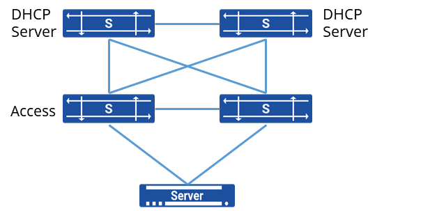
The device supports dual DHCP server hot standby, as shown in the diagram. Two core switches each deploy a DHCP server, and when servers are connected to the network via dual network cards, the two DHCP servers can achieve load balancing and failover.
The servers compute a hash value from the client_identifier field in the DHCP request packet, generating a value between 1 and 255.
Based on a configured weight distribution percentage, these 255 values are divided between the two DHCP servers. For instance, if DHCP Server A has a weight of 80 and DHCP Server B has a weight of 20, then 80% of the values (204 values) will be assigned to Server A, and the remaining 20% (51 values) to Server B.
When a DHCP request is received from a client, the two DHCP servers will check if the hash value of the client falls within their respective assigned range.
- The server with the assigned range will allocate an IP address to the client.
- The server that did not allocate the IP will synchronize the lease information to avoid conflicts.
DHCP failover uses a specific protocol to manage communication and synchronization between the primary and secondary servers. This protocol handles:
- State Updates: Ensuring both servers are aware of the client’s current lease status.
- Heartbeat Mechanism: To detect when the primary or secondary server becomes unreachable.
- Failover Procedures: Automatically triggering a failover if the primary server is detected to be down.
Handling of Failover Events
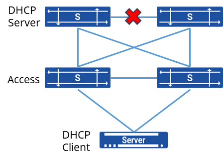
The two DHCP servers periodically send heartbeat messages to ensure normal communication between them. If no response is received after three consecutive attempts, the servers consider the communication as interrupted and enter the “communications_interrupted” state. In this state, each server manages its own address pool independently.
When the servers are in the communications_interrupted state and receive a DHCP request from a client, both servers will assign different IP addresses to the client. The client will select the IP address from the first received DHCP reply and confirm it.
Once communication between the servers is restored, they will synchronize the address allocation information that occurred during the communication failure to ensure consistency.
If communication is not restored after a certain period, the remaining active DHCP server will assume that the other server has failed and gone offline. After the lease time for the address pool expires, the active server will take control of the entire address pool and will have the authority to assign addresses to clients from the full range of available IP addresses.
Configuring the Device as a DHCP Server
Section titled “Configuring the Device as a DHCP Server”DHCP Server Configuration
Section titled “DHCP Server Configuration”| Operation | Command | Description |
|---|---|---|
| Enter the system configuration view | configure terminal | |
| Create a DHCP address pool and enter the DHCP configuration view | dhcp pool name | |
| Configure the dynamic allocation subnet for the DHCP address pool | network ip-address mask | |
| Specify the IP address range for dynamic IP allocation | address-pool ip-address ip-address | |
| Configure the gateway for DHCP clients | routers ip-address | |
| Configure DNS addresses for DHCP clients | dns ip-address | |
| Set the lease duration for dynamically allocated IP addresses | lease-time default-time max-time | |
| Configure the TFTP server address for DHCP clients | tftp-server server-name | |
| Specify the boot file name for DHCP clients | bootfile-name bootfile | |
| Set the next server IP address for DHCP clients | next-server ip-address | |
| Bind the DHCP server to the interfac | interface ethernet id | interface vlan vlan-id dhcp select server |
Configuring DHCP Option
Section titled “Configuring DHCP Option”The DHCP server can use the DHCP Option feature to recognize specific vendor information from the DHCP client’s request packets. This allows the server to allocate customized network parameters based on the client’s vendor or specific needs.
- Create a DHCP Client Classification Group Define a group that will classify DHCP clients based on specific criteria, such as option 93
dhcp class <name>if-match rule <ID> option 93 hex <value>- Create an Option Group Define an option group that will hold the custom DHCP options for the classified clients.Set the required DHCP options within this option group. Example to configure Option 43 for custom vendor information:
dhcp option-group <ID>option 43 hex <hex-value>Example to configure a tftp server:
tftp-server <ip-address>- Apply the Option Group to the DHCP Client Classification Group Bind the option group to the DHCP client classification group, so that clients matching the classification receive the custom options.
dhcp pool <name>class <name> option-group <ID>DHCP Failover Configuration
Section titled “DHCP Failover Configuration”| Operation | Command | Description |
|---|---|---|
| Configure DHCP failover | dhcp failover name | |
| Specify the local address for DHCP server peer communication | address { A.B.C.D | Loopback0} | Define the local IP address used for communication between the DHCP servers. |
| Specify the peer address of the DHCP server | peer address A.B.C.D | Set the IP address of the peer DHCP server for failover communication. |
| Assign the Primary/Secondary role in DHCP failover | role {primary|secondary} | Specify the role of the DHCP server in the failover configuration, either as primary or secondary. |
| Assign HASH value weight for DHCP client allocation | split value | Configure the hash value weight distribution between the two DHCP servers to manage load balancing. |
| Enable DHCP failover for a specific DHCP address pool | failover name | Activate the DHCP failover function for a particular address pool to allow redundancy and load balancing. |
Configuring the Device as a DHCP Client
Section titled “Configuring the Device as a DHCP Client”Once the device is configured as a DHCP client, it can obtain an IP address and other information from the DHCP server. However, if the IP address assigned by the DHCP server to the interface falls within the same subnet as the IP address of another interface on the device, the interface will not use that IP address.
| Operation | Command | Description |
|---|---|---|
| Enter the system configuration view | configure terminal | |
| Enter the interface configuration view | interface ethernet interface vlan | |
| Enable DHCP on the interface | ip address dhcp-alloc |
DHCP Failover Configuration Example
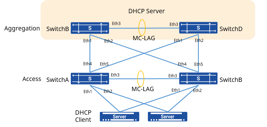
Section titled “DHCP Failover Configuration Example”Network requirements
A company has a cluster of servers, and to ensure the stability of server access, the servers are connected to the network through dual uplinks. The servers obtain their IP addresses dynamically from a DHCP server. To ensure the reliability of the DHCP service, DHCP servers are deployed on two separate aggregation devices. Both the aggregation devices and the access devices run MC-LAG for redundancy and load balancing.
Procedure
- Create an aggregation interface (port-channel) and add the physical interfaces connecting to the server and the aggregation devices. # Access Switch A
sonic(config)# interface link-aggregation 1sonic(config)# interface ethernet 1sonic(config-if-1)# link-aggregation-group 1sonic(config)# interface link-aggregation 2sonic(config)# interface ethernet 2sonic(config-if-2)# link-aggregation-group 2sonic(config)# interface link-aggregation 3sonic(config)# interface ethernet 4sonic(config-if-4)# link-aggregation-group 3sonic(config)# interface ethernet 5sonic(config-if-5)# link-aggregation-group 3# Switch B
sonic(config)# interface link-aggregation 1sonic(config)# interface ethernet 1sonic(config-if-1)# link-aggregation-group 1sonic(config)# interface link-aggregation 2sonic(config)# interface ethernet 2sonic(config-if-2)# link-aggregation-group 2sonic(config)# interface link-aggregation 3sonic(config)# interface ethernet 4sonic(config-if-4)# link-aggregation-group 3sonic(config)# interface ethernet 5sonic(config-if-5)# link-aggregation-group 3- Create a aggregation interface and add the physical interfaces connecting Switch A and Switch B as a peerlink. # Switch A
sonic(config)# interface link-aggregation 4sonic(config)# interface ethernet 3sonic(config-if-3)# link-aggregation-group 4# Switch B
sonic(config)# interface link-aggregation 4sonic(config)# interface ethernet 3sonic(config-if-3)# link-aggregation-group 4- Create VLAN 100 and add aggregation interface # Switch A
sonic(config)# vlan 100sonic(config)# interface link-aggregation 1sonic(config-lagif-1)# switchport access vlan 100sonic(config)# interface link-aggregation 2sonic(config-lagif-2)# switchport access vlan 100sonic(config)# interface link-aggregation 3sonic(config-lagif-3)# switchport access vlan 100# Switch B
sonic(config)# vlan 100sonic(config)# interface link-aggregation 1sonic(config-lagif-1)# switchport access vlan 100sonic(config)# interface link-aggregation 2sonic(config-lagif-2)# switchport access vlan 100sonic(config)# interface link-aggregation 3sonic(config-lagif-3)# switchport access vlan 100- Create VLAN 200 and assign an IP address to it. Add the peerlink aggregation interface to VLAN 200. # Switch A
sonic(config)# vlan 200sonic(config)# interface link-aggregation 4sonic(config-lagif-4)# switchport trunk vlan 200sonic(config-lagif-4)# switchport trunk vlan 100sonic(config)# interface vlan 200sonic(config-vlanif-200)# ip address 10.1.1.24/24# Switch B
sonic(config)# vlan 200sonic(config)# interface link-aggregation 4sonic(config-lagif-4)# switchport trunk vlan 200sonic(config-lagif-4)# switchport trunk vlan 100sonic(config)# interface vlan 200sonic(config-vlanif-200)# ip address 10.1.1.48/24- Configure the MC-LAG, specify the member LAG, peerlink, and peerlink IP address. # Switch A
sonic(config)# mclag domain 1sonic(mclag-domain)# local-address 10.1.1.24sonic(mclag-domain)# peer-address 10.1.1.48sonic(mclag-domain)# peer-link lag 4sonic(mclag-domain)# member lag 1sonic(mclag-domain)# member lag 2sonic(mclag-domain)# member lag 3# Switch B
sonic(config)# mclag domain 1sonic(mclag-domain)# local-address 10.1.1.48sonic(mclag-domain)# peer-address 10.1.1.24sonic(mclag-domain)# peer-link lag 4sonic(mclag-domain)# member lag 1sonic(mclag-domain)# member lag 2sonic(mclag-domain)# member lag 3- Configure MC-LAG and VLAN on aggregation device # Switch C
sonic(config)# interface link-aggregation 1sonic(config)# interface ethernet 1sonic(config-if-1)# link-aggregation-group 1sonic(config)# interface ethernet 2sonic(config-if-2)# link-aggregation-group 1sonic(config)# vlan 100sonic(config)# interface link-aggregation 1sonic(config-lagif-1)# switchport access vlan 100sonic(config)# interface vlan 100sonic(config-vlanif-100)# ip address 192.168.100.1/24# Switch B
sonic(config)# interface link-aggregation 1sonic(config)# interface ethernet 1sonic(config-if-1)# link-aggregation-group 1sonic(config)# interface ethernet 2sonic(config-if-2)# link-aggregation-group 1sonic(config)# vlan 100sonic(config)# interface link-aggregation 1sonic(config-lagif-1)# switchport access vlan 100sonic(config)# interface vlan 100sonic(config-vlanif-100)# ip address 192.168.100.1/24- Create VLAN 200 and add peerlink Interface to the VLAN # Switch C
sonic(config)# vlan 200sonic(config)# interface link-aggregation 2sonic(config-lagif-2)# switchport trunk vlan 200sonic(config-lagif-2)# switchport trunk vlan 100sonic(config)# interface vlan 200sonic(config-vlanif-200)# ip address 10.1.1.24/24# Switch D
sonic(config)# vlan 200sonic(config)# interface link-aggregation 2sonic(config-lagif-2)# switchport trunk vlan 200sonic(config-lagif-2)# switchport trunk vlan 100sonic(config)# interface vlan 200sonic(config-vlanif-200)# ip address 10.1.1.48/24- Configure the MC-LAG, specify the member LAG, peerlink, and peerlink IP address. # Switch C
sonic(config)# mclag domain 1sonic(mclag-domain)# local-address 10.1.1.24sonic(mclag-domain)# peer-address 10.1.1.48sonic(mclag-domain)# peer-link lag 2sonic(mclag-domain)# member lag 1# Switch D
sonic(config)# mclag domain 1sonic(mclag-domain)# local-address 10.1.1.48sonic(mclag-domain)# peer-address 10.1.1.24sonic(mclag-domain)# peer-link lag 2sonic(mclag-domain)# member lag 1- Create DHCP address pool # Switch C
sonic(config)# dhcp failover testsonic(config-dhcp-failover-test)# address 10.1.1.24sonic(config-dhcp-failover-test)# peer 10.1.1.48sonic(config-dhcp-failover-test)# role primarysonic(config-dhcp-failover-test)# split 50sonic(config)# dhcp pool testsonic(config-dhcp-pool-test)# address-pool 192.168.100.2 192.168.100.254sonic(config-dhcp-pool-test)# network 192.168.100.0 255.255.255.0sonic(config-dhcp-pool-test)# routers 192.168.100.1sonic(config-dhcp-pool-test)# failover testsonic(config)# interface vlan 100sonic(cofnig-vlanif-100)# dhcp select server# Switch D
sonic(config)# dhcp failover testsonic(config-dhcp-failover-test)# address 10.1.1.48sonic(config-dhcp-failover-test)# peer 10.1.1.24sonic(config-dhcp-failover-test)# role secondarysonic(config-dhcp-failover-test)# split 50sonic(config)# dhcp pool testsonic(config-dhcp-pool-test)# address-pool 192.168.100.2 192.168.100.254sonic(config-dhcp-pool-test)# network 192.168.100.0 255.255.255.0sonic(config-dhcp-pool-test)# routers 192.168.100.1sonic(config-dhcp-pool-test)# failover testsonic(config)# interface vlan 100sonic(cofnig-vlanif-100)# dhcp select server