
VLAN Configuration
Introduction
Section titled “Introduction”Ethernet is a data network communication technology based on CSMA/CD (Carrier Sense Multiple Access/Collision Detection), which utilizes a shared communication medium. When the number of hosts increases, it can lead to severe issues like collisions, broadcast storms, performance degradation, and even network unavailability.
Although using switches to interconnect Local Area Networks (LANs) can mitigate collision problems, it still fails to isolate broadcast messages and enhance network quality. In response to these challenges, Virtual Local Area Network (VLAN) technology emerged. VLAN logically divides a physical LAN into multiple broadcast domains, allowing direct communication between hosts within the same VLAN while preventing direct communication between different VLANs. This containment of broadcast messages within their respective VLANs improves network isolation and performance.
Explanation of Principles
Section titled “Explanation of Principles”Interface Type
Section titled “Interface Type”Different types of interfaces on a device handle VLAN tagging differently when forwarding packets. Based on their VLAN tagging behavior, interfaces can be categorized into three types: Access, Trunk, and Hybrid interfaces.
Access Interface This interface adds the interface’s Port VLAN ID (PVID) to untagged incoming packets. It only allows tagged packets with VLAN IDs matching the interface’s PVID to pass through. Outgoing packets from this interface are always untagged, making it suitable for connecting user terminals.
Trunk Interface It permits multiple VLAN tags to pass through. Outgoing packets from this interface have no VLAN tag if their VLAN matches the interface’s default VLAN. Other VLANs must have a VLAN tag. Trunk interfaces are often used for interconnecting network transmission equipment.
Hybrid Interface This interface type is not supported by the current device and is not further described.
Interface Default VLAN
Section titled “Interface Default VLAN”In addition to configuring the VLANs allowed to traverse a port, you can also define a default VLAN for the port, known as the Port VLAN ID (PVID). When an untagged packet is received on the port, it is assumed to belong to the default VLAN.
For Access ports, the default VLAN corresponds to the VLAN the interface has been configured to join in access mode.
Packet Transmission and Reception Rules
Section titled “Packet Transmission and Reception Rules”| Interface Type | Ingress | Egress | |
|---|---|---|---|
| Untag | Tag | ||
| Access | Adding Default VLAN ID of the interface | When the VLAN ID of a packet matches the default VLAN ID of the interface, the interface receives the packet. | When the VLAN ID of a packet matches the interface’s default VLAN ID, the interface removes the tag and sends the packet. When the VLAN ID of a packet differs from the interface’s default VLAN ID and the packet’s VLAN ID is one of the VLAN IDs allowed through the interface: the original tag is preserved, and the packet is sent |
| Trunk | Adding Default VLAN ID of the interface | When the VLAN ID of a packet is in the list of VLAN IDs allowed through the interface, the packet is received. When the VLAN ID of a packet is not in the list of VLAN IDs allowed through the interface, the packet is discarded. | The VLAN tag of the packet remains unchanged. |
Configuring Interface VLAN
Section titled “Configuring Interface VLAN”| Operation | Command | Description |
|---|---|---|
| Enter the system configuration view | configure terminal | |
| Create a VLAN | vlan ID | |
| Enter the interface view | interface ethernet ID | |
| Assign an access VLAN | switchport access vlan ID | |
| Assign a trunk VLAN | switchport trunk vlan ID | |
| Remove a VLAN | no switchport vlan ID |
Voice VLAN Configuration
Section titled “Voice VLAN Configuration”The Voice VLAN feature enables switch ports to transmit voice traffic from IP phones with an administrator-defined priority. When multiple devices (such as personal computers and IP phones) are connected to the same port, the port can be configured to use one VLAN for voice traffic and another VLAN for data traffic. IP Voice (VoIP) traffic is inherently time-sensitive: low latency is crucial for a network to provide acceptable service. The switch supports separating voice and data traffic entering the port and can accelerate the forwarding of Voice VLAN traffic, ensuring that the sound quality of IP phones is not disturbed when data traffic on the port is high.
| Operation | Command | Description |
|---|---|---|
| Enter the interface view | interface ethernet interface-id | Enter the specified Ethernet interface view |
| Configure the interface to publish MED TLV | lldp ports med-policy voice[vlan vid ][vlan-type {tagged|untagged}] [priority value ] [dscp value ] | Configure the interface to publish the MED TLV, which is used to automatically configure information such as the VLAN and priority of IP phones connected to the device. vid: Specify the voice VLAN ID to allow the traffic of IP phones to enter an independent VLAN. vlan-type: Define the tagging method for voice traffic: “tagged” is the most common, allowing the separation of voice (tagged) and data (untagged) traffic on the same port. priority: Specify the 802.1p (CoS) priority (0-7), with a higher value indicating a higher forwarding priority. dscp: Specify the DSCP (Differentiated Services Code Point) (0-63), which identifies the service level of voice traffic at the network layer, with a higher value indicating a higher forwarding priority. |
Batch-VLAN Configuration
Section titled “Batch-VLAN Configuration”Batch-VLAN Principle
Section titled “Batch-VLAN Principle”When a device needs to allow a large number of VLANs to pass between interfaces at once, the operations of creating VLANs and adding interfaces to VLANs must be repeated, which can take time to load and apply the configuration. The device offers a more convenient batch method to create VLANs that share the same Layer 2 attributes.
By creating a batch-VLAN group, interfaces can be added to VLANs, simplifying the business logic and accelerating the time it takes for configurations to be applied and take effect.
It is important to note that member VLANs within a batch-VLAN cannot be extracted and used as regular VLANs independently.
Batch- VLAN Configuration
Section titled “Batch- VLAN Configuration”| Operation | Command | Description |
|---|---|---|
| Create a batch-vlan group | batch-vlan-group <ID> | |
| Add the VLAN ID List to be Allowed | vlan-ids <vlan-range> | Specifies the range of VLANs to be included in the batch. You can separate VLAN ranges using - and ,. For example, 10-20,30,40-50. |
| Configure the List of Interfaces to Allow VLAN Traffic | switchport trunk ethernet <port-range> | Specifies the range of interfaces. This range defines the ports on which the VLANs in the batch-VLAN group will be allowed. |
Display and Maintenance
Section titled “Display and Maintenance”| Operation | Command | Description |
|---|---|---|
| Display VLAN summary information | show vlan summary | |
| Display detailed information about a specific VLAN | show vlan vlan-id | |
| Display information for all VLANs | show vlan all |
Configuration Example
Section titled “Configuration Example”Configuring VLAN Assignment Based on Interfaces for Intra-VLAN Communication
Section titled “Configuring VLAN Assignment Based on Interfaces for Intra-VLAN Communication”Network requirements
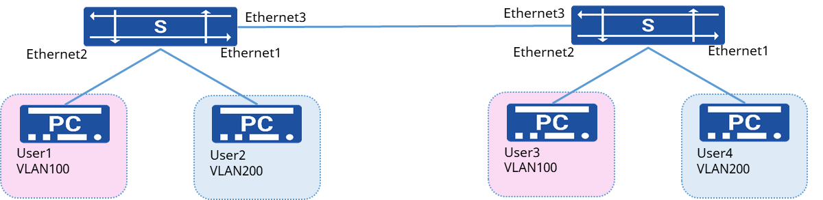
Suppose User 1 and User 3 of a company belong to the same department but access the network through different devices, User 2 and User 4 belong to the same department and access the network through different devices but belong to different VLANs, where Department A uses VLAN 100 and Department B uses VLAN 200.
Procedure
- Configure Device A
# Create VLAN and add the interface to the VLAN
sonic(config)# vlan 100sonic(config)# vlan 200sonic(config)# interface ethernet 1sonic(config-if-1)# switchport access vlan 200sonic(config)# interface ethernet 2sonic(config-if-2)# switchport access vlan 100sonic(config)# interface ethernet 3sonic(config-if-3)# switchport trunk vlan 100sonic(config-if-3)# switchport trunk vlan 200- Device B and DeviceA configuration is the same
Verify configuration
- User 1 and User 3 can ping each other, but neither can ping User 2 and User 4, and User 2 and User 4 can ping each other, but not User 1 and User 3.
- View VLAN configuration information.
sonic# show vlan brief+----------+------------+-----------+--------------+--------------------+| VLAN ID | IP Address | Ports | Port Tagging | DHCP Helper Address|+==========+============+===========+==============+====================+| 100 | | Ethernet2 | untagged | || | | Ethernet3 | tagged | |+----------+------------+-----------+--------------+--------------------+| 200 | | Ethernet1 | untagged | || | | Ethernet3 | tagged | |+----------+------------+-----------+--------------+--------------------+Configuring Batch-VLAN
Section titled “Configuring Batch-VLAN”Network Requirement
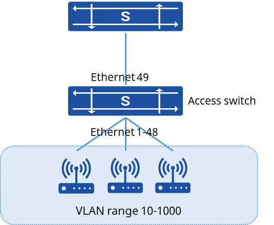
The device is used as an access switch, connected to Access Points (APs). The APs have multiple VLANs configured to differentiate various services or user permissions. The access switch must allow these VLANs to pass through. Additionally, VLAN 1 is used as the in-band management VLAN on the access switch.
Procedure
- Create Batch-VLAN Group
sonic(config)# batch-vlan-group 1sonic(config-batch-vlan-group-1)# vlan-ids 10-1000sonic(config-batch-vlan-group-1)# switchport trunk ethernet 1-48sonic(config-batch-vlan-group-1)# exit- Ensure VLAN 1 is Configured for Management
sonic(config)# vlan 1sonic(config)# interface ethernet 49sonic(config-if-49)# switchport access vlan 1sonic(config-if-49)# exitsonic(config)# interface vlan 1sonic(config-vlanif-1)# ip address 192.168.100.1/24Verify configuration
sonic# show vlan summary+-----------+------------------+---------------+----------------+-----------------------+| VLAN ID | IP Address | Ports | Port Tagging | DHCP Helper Address |+===========+==================+===============+================+=======================+| 1 | 192.168.100.1/24 | Ethernet49 | untagged | |+-----------+------------------+---------------+----------------+-----------------------+| 10-1000 | | Ethernet1-48 | tagged | |+-----------+------------------+---------------+----------------+-----------------------+