
MC-LAG Configuration
Introduction
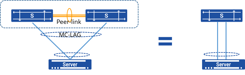
Section titled “Introduction”MC-LAG (Multi Chassis Link Aggregation Group) is a mechanism for achieving link aggregation across devices. It involves aggregating links between one device and two other devices, combining the benefits of regular link aggregation while providing device-level redundancy.
MC-LAG introduces a form of horizontal virtualization, where two physical devices are virtualized as a single logical device. This virtual “single device” is used to perform “one-to-one” link aggregation with the connected upstream or downstream devices.
The following information is synchronized between MC-LAG peers:
- System information
Ensures synchronization of MAC addresses for MC-LAG member ports, enabling the “system ID” field in LACP (Link Aggregation Control Protocol) messages sent to the server to be the same, achieving cross-device link aggregation.
- MC-LAG member port configuration information
Records details like names of local and remote MC-LAG member ports for consistency checks.
- MC-LAG member port status information
Keeps track of the status of local and remote MC-LAG member ports to ensure isolation between the peer-link and MC-LAG member ports in fault-free scenarios, and to release isolation between the peer-link and the same-named port on the remote side in case of a failure in the remote MC-LAG member port.
- ARP (Address Resolution Protocol) information
ARP entries related to MC-LAG member ports are synchronized between MC-LAG peers.
- FDB (Forwarding Database) information
FDB entries associated with MC-LAG member ports are synchronized between MC-LAG peers.
Explanation of Principles
Section titled “Explanation of Principles”As shown in the diagram, on two separate switches, a cross-device link aggregation group is established and connected to ordinary link aggregation ports on the user side. Once the MC-LAG is established, entries can be synchronized between devices. The direct link between Switch1 and Switch2 serves as the peer-link interface, used for protocol messages and forwarding traffic during failures. The links connecting the switches to users, acting as member interfaces of the MC-LAG, handle incoming traffic, distribute loads, and provide backup protection for the links.
In the context of MC-LAG, SONiC employs a lightweight Inter-Chassis Communication Protocol (ICCP) on the control plane, conducting only a limited amount of consistency checks and information synchronization while ensuring the functionality.
ICCP, defined in RFC7275, serves as the standard protocol for inter-chassis communication. In the MC-LAG implementation, the ICCP protocol establishes connections between MC-LAG peer devices using TCP port 8888. This streamlined ICCP protocol primarily focuses on configuring consistency checks and synchronizing ARP and MAC table entries.
Between the two MC-LAG peer devices, the local_ip and peer_ip addresses are used as the source and destination addresses for establishing the TCP connection to form the ICCP neighbor relationship. Once the ICCP connection is successfully established, the system sends heartbeat messages to the peer every 1 second. If no heartbeat messages are received for 15 consecutive intervals, the connection is deemed timed out, leading to the termination of the ICCP connection.
MC-LAG Loop Prevention Mechanism
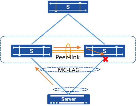
Section titled “MC-LAG Loop Prevention Mechanism”MC-LAG itself comes with a loop prevention mechanism, as shown in the diagram. When a device receives a broadcast packet from the MC-LAG side, this broadcast packet is transmitted through the Peer-link link to the opposite device. Due to the flow isolation between the peer-link link and the MC-LAG member interfaces, any traffic coming in from the peer-link port will not be forwarded out through the MC-LAG member interfaces. This effectively prevents the formation of loops.
MC-LAG Fault Handling
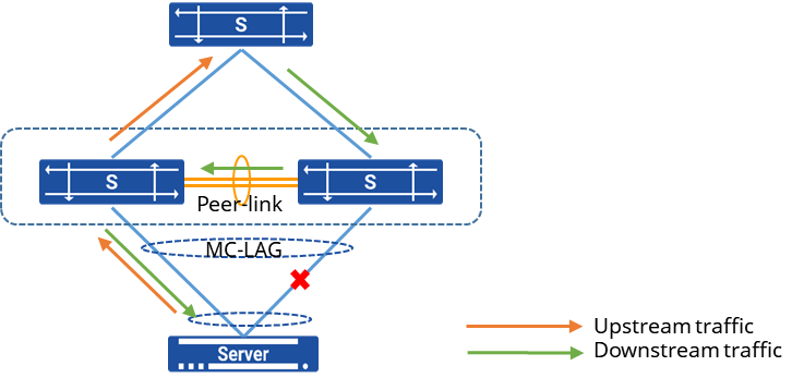
Section titled “MC-LAG Fault Handling”As illustrated in the diagram, in the event of a link failure on the MC-LAG side, the device will proactively update the interface information for the corresponding terminal’s MAC table entries and ARP table entries to reflect the peer-link interface. Consequently, downstream traffic will be forwarded through the peer-link interface to the other device, ensuring seamless fault handling for the user. Once the fault is rectified, and the MC-LAG interface is back up, traffic will resume its normal forwarding behavior.
MC-LAG Configuration
Section titled “MC-LAG Configuration”Basic Configuration
Section titled “Basic Configuration”| Operation | Command | Description |
|---|---|---|
| Enter the system configuration view | configure terminal | |
| Enter the link-aggregation configuration view and create a link-aggregation group | interface link-aggregation lag-id | Only supported single domain the range of 1 to 4095. |
| Create a MC-LAG domain | mclag domain domain-id | |
| Delete a MC-LAG domain | no mclag domain domain-id | |
| Configure peerlink interface | peer-link {ethernet|link-aggregation} name | |
| Configure the peer IP address for the MC-LAG control link | peer-address A.B.C.D | |
| Set the local IP address for the MC-LAG control link | local-address A.B.C.D | |
| Add a member lag port to the MC-LAG group | member lag lag-id | |
| Remove a member lag port from the MC-LAG group | no member lag lag-id | |
| Enable the active-standby mode of MC-LAG member ports | member lag* lag-id* active-backup | Add MC-LAG member ports and configure them in active-standby mode. The device will automatically determine the active and standby interfaces on the device side based on the traffic conditions of the active and standby ports of the server. |
| Disable the active-standby mode of MC-LAG member ports | no member lag* lag-id*active-backup | |
| Enter the configuration view for a VLAN interface | interface vlan vlan-id | |
| Modify the MAC address of a VLAN interface | mac_address HH:HH:HH:HH:HH:HH | To make two MC-LAG switches appear as the same logical gateway to the outside, it is necessary to manually configure the MAC addresses of the service gateways on both ends to be consistent. This avoids ARP conflicts and abnormal traffic forwarding caused by downstream devices learning different MAC addresses. |
In actual deployment, the mode of MC-LAG member ports must correspond to the binding mode of the server’s network card:
- When the server adopts the active-standby mode (bond mode 1), the active-standby mode of the MC-LAG member ports must be enabled.
- When the server adopts the load balancing mode (such as bond mode 0, 2), the member LAG ports should be configured as static aggregation (default).
- When the server adopts dynamic link aggregation (bond mode 4), the member LAG ports need to be configured as dynamic LACP aggregation.
DAD Link Configuration (optional)
Section titled “DAD Link Configuration (optional)”The DAD link (Dual Active Detection link) is a Layer 3 interworking link used for sending dual active detection messages between MC-LAG peers. When a Peer-link failure is detected, the interface status of the standby device negotiated by MC-LAG, except for the management and peer-link interfaces, is set to Error Down. This ensures that only the active device forwards traffic and prevents network conflicts.
It is recommended to first complete the MC-LAG configuration and use the `show mclag state` command to confirm that 【The MCLAG’s keepalive is: OK】 before configuring the DAD link, to prevent the device port from being mistakenly Error Down.
| Operation | Command | Description |
|---|---|---|
| Enter the system configuration view | configure terminal | - |
| Enter the MC-LAG domain | mclagdomain domain-id | Enter the created MC-LAG domain |
| Configure the source IP address of DAD heartbeat packets | dad local-address A.B.C.D | It is recommended to use the management port IP address. |
| Configure the destination IP address for DAD heartbeat packets | dad peer-address A.B.C.D | It is necessary to ensure that the configured local-address and peer-address are reachable at the third layer. |
| Configure the Error down delay time | dad detection-delay time | time: Value range: 0-255 (default 60), unit: second When the Peer-link fails but DAD detection is normal, Error Down will be triggered on the standby device after the configured delay time to prevent session flapping. |
| Configure the error down recovery delay time for MC-LAG member LAGs | dad recovery-delay mlag time | time: Value range: 0-255 (default 60), unit: second When the Peer-link fault is recovered, the Error down state of the MC-LAG member LAG will be restored after the configured delay time to prevent session flapping. |
| Configure the error down recovery delay time for MC-LAG non-member LAG | dad recovery-delay non-mlag time | time: Value range: 0-255 (default 0), unit: second When the Peer-link fault is recovered, the Error down state of the LAG that is not an MC-LAG member will be restored after the configured delay time to prevent session flapping. |
| Specify the VRF to which the DAD message belongs | dad vrf vrf-name | When using the management network port as the source for sending DAD packets and the management network port is designated as MGMT VRF, this command needs to be used to specify the source of DAD as MGMT VRF. |
Display and Maintenance
Section titled “Display and Maintenance”| Operation | Command | Description |
|---|---|---|
| Check the relevant information about MC-LAG | show mclag state | - |
| Check the Error down status of the interface | show interface errdown | Check the interface that was forced to shut down due to DAD disconnection |
| Enable the M-LAG configuration consistency check function and specify the check mode | consistency-check-action {idle|default|graceful} | idle: Only check for consistency without taking any action. default: Check for consistency and shut down the member interfaces that are inconsistent. graceful: Check for consistency, shut down the member ports of devices with the standby role, and keep the active devices in the UP state. |
| The default state is idle. | ||
| Check the results of member consistency checks | show mclag consistency_check_result | pass : Configuration is consistent failed : Configuration is inconsistent |
Configuration Example
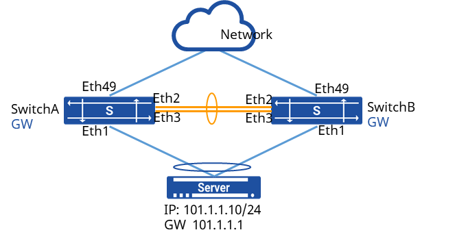
Section titled “Configuration Example”Network requirements
A server is dual-homed to an Ethernet network through M-LAG. The customer requires high service reliability. Link aggregation between the server and devices only achieves link-level reliability, and a fault on a device may cause service interruption. M-LAG can be configured. When devices work properly, links load balance traffic and a fault of any device does not affect services. High service reliability is therefore ensured.
Procedure
- Create an aggregation port and add the physical interfaces connected to Server and Switch C to the aggregation port group
# Switch A
sonic(config)# interface link-aggregation 1sonic(config)# interface ethernet 1sonic(config-if-1)# link-aggregation-group 1# Switch B
sonic(config)# interface link-aggregation 1sonic(config)# interface ethernet 1sonic(config-if-1)# link-aggregation-group 1- Create an aggregation port and add the interconnection port between Switch A and Switch B to the aggregation group as the peerlink interface # Switch A
sonic(config)# interface link-aggregation 2sonic(config)# interface ethernet 2sonic(config-if-2)# link-aggregation-group 2sonic(config)# interface ethernet 3sonic(config-if-3)# link-aggregation-group 2# Switch B
sonic(config)# interface link-aggregation 2sonic(config)# interface ethernet 2sonic(config-if-2)# link-aggregation-group 2sonic(config)# interface ethernet 3sonic(config-if-3)# link-aggregation-group 2- Create VLAN100 to add all aggregation ports to VLAN # Switch A
sonic(config)# vlan 100sonic(config)# interface link-aggregation 1sonic(config-lagif-1)# switchport access vlan 100sonic(config)# interface link-aggregation 2sonic(config-lagif-2)# switchport access vlan 100sonic(config)# interface vlan 100sonic(config-vlanif-100)# ip address 101.1.1.1/24sonic(config-vlanif-100)# mac-address 00:00:00:11:22:10# Switch B
sonic(config)# vlan 100sonic(config)# interface link-aggregation 1sonic(config-lagif-1)# switchport access vlan 100sonic(config)# interface link-aggregation 2sonic(config-lagif-2)# switchport access vlan 100sonic(config)# interface vlan 100sonic(config-vlanif-100)# ip address 101.1.1.1/24sonic(config-vlanif-100)# mac-address 00:00:00:11:22:10- Create VLAN200 and configure the IP address to add the peerlink interface to the VLAN # Switch A
sonic(config)# vlan 200sonic(config)# interface link-aggregation 2sonic(config-lagif-2)# switchport trunk vlan 200sonic(config-lagif-2)# switchport trunk vlan 100sonic(config)# interface vlan 200sonic(config-vlanif-200)# ip address 10.1.1.24/24# Switch B
sonic(config)# vlan 200sonic(config)# interface link-aggregation 2sonic(config-lagif-3)# switchport trunk vlan 200sonic(config-lagif-2)# switchport trunk vlan 100sonic(config)# interface vlan 200sonic(config-vlanif-200)# ip address 10.1.1.48/24- Create an MC-LAG and specify the member interface, peerlink interface and peerlink port IP address # Switch A
sonic(config)# mclag domain 1sonic(mclag-domain)# local-address 10.1.1.24sonic(mclag-domain)# peer-address 10.1.1.48sonic(mclag-domain)# peer-link lag 2sonic(mclag-domain)# member lag 1# Switch B
sonic(config)# mclag domain 1sonic(mclag-domain)# local-address 10.1.1.48sonic(mclag-domain)# peer-address 10.1.1.24sonic(mclag-domain)# peer-link lag 2sonic(mclag-domain)# member lag 1Verify configuration
- Check MC-LAG status
sonic# show mclag stateThe MCLAG's keepalive is: OKMCLAG info sync is: completedDomain id: 1MCLAG session Channel: Primary channelVRF Name: defaultconsistency Check Action: idleLocal Ip: 10.1.1.48Peer Ip: 10.1.1.24Peer Link Interface: PortChannel0003Keepalive time: 1sesssion Timeout : 15Peer Link Mac: 00:11:24:1a:1b:61Admin Role: NoneRole: StandbyMCLAG Interface: PortChannel0001Loglevel: DEBUG- The server can ping the gateway and check the MAC address of the device # Use the Server ping gateway address
Testuser@78:~$ping 101.1.1.1PING 101.1.1.1 (101.1.1.1) 56(84) bytes of data.64 bytes from 101.1.1.1: icmp_seq=1 ttl=64 time=3.38 ms64 bytes from 101.1.1.1: icmp_seq=2 ttl=64 time=1.33 ms64 bytes from 101.1.1.1: icmp_seq=3 ttl=64 time=1.32 ms64 bytes from 101.1.1.1: icmp_seq=4 ttl=64 time=1.29 ms^C--- 101.1.1.1 ping statistics ---4 packets transmitted, 4 received, 0% packet loss, time 3005msrtt min/avg/max/mdev = 1.291/1.835/3.389/0.897 ms # Display the MAC address on Switch B device
sonic# show mac-address No. Vlan MacAddress Port Type----- ------ ----------------- --------------- ------- 1 101 00:51:82:11:0F:78 PortChannel0001 Dynamic- Cut off the link between SwitchB and SwitchC, use the server ping gateway again, and still be able to ping, and check the MAC address of the device at this time # Use the Server ping gateway address
Testuser@78:~$ping 101.1.1.1PING 101.1.1.1 (101.1.1.1) 56(84) bytes of data.64 bytes from 101.1.1.1: icmp_seq=1 ttl=64 time=3.38 ms64 bytes from 101.1.1.1: icmp_seq=2 ttl=64 time=1.33 ms64 bytes from 101.1.1.1: icmp_seq=3 ttl=64 time=1.32 ms64 bytes from 101.1.1.1: icmp_seq=4 ttl=64 time=1.29 ms^C--- 101.1.1.1 ping statistics ---4 packets transmitted, 4 received, 0% packet loss, time 3005msrtt min/avg/max/mdev = 1.291/1.835/3.389/0.897 ms# Display the MAC address on your Switch B device
sonic# show mac-address No. Vlan MacAddress Port Type----- ------ ----------------- --------------- ------- 1 101 00:51:82:11:0F:78 PortChannel0002 DynamicMC-LAG+STP Configuration Example
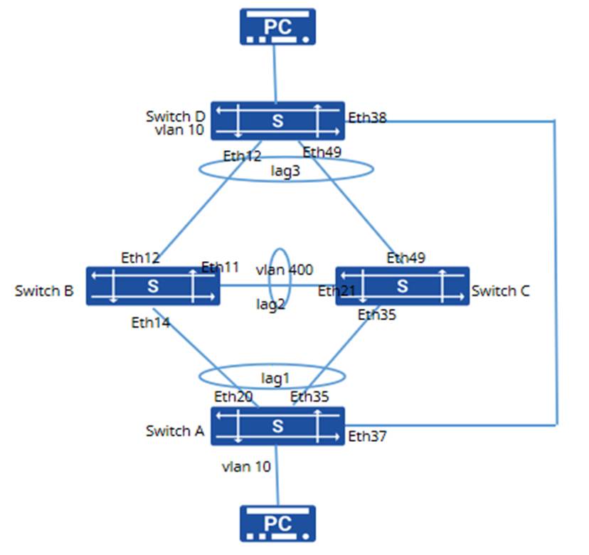
Section titled “MC-LAG+STP Configuration Example”M-LAG itself has a loop avoidance mechanism. Under normal circumstances, no loops will be generated in an M-LAG network. In a multi-level M-LAG network, loops may occur in the network when there are errors in network setup, when initializing M-LAG configurations, or when devices restart with empty configurations. STP can be deployed to avoid loops.
Networking Requirements
The switch adopts cross-device link aggregation technology to ensure high reliability of services at the device level. During normal operation, the links perform load sharing, and when the STP configuration is enabled, the links can successfully break loops, ensuring that data packet forwarding is not affected.
Configuration steps
1. Create an aggregation port and add the physical interfaces connected to the Switch to the aggregation port group respectively.
#Switch A:
sonic(config)# interface link-aggregation 1sonic(config)# interface ethernet 20sonic(config-if-20)# link-aggregation-group 1sonic(config-if-20)# exitsonic(config)# interface ethernet 35sonic(config-if-35)# link-aggregation-group 1sonic(config-if-35)# exit#Switch B
sonic(config)# interface link-aggregation 1sonic(config)# interface link-aggregation 2sonic(config)# interface link-aggregation 3sonic(config)# interface ethernet 14sonic(config-if-14)# link-aggregation-group 1sonic(config-if-14)# exitsonic(config)# interface ethernet 11sonic(config-if-11)# link-aggregation-group 2sonic(config-if-11)# exitsonic(config)# interface ethernet 12sonic(config-if-12)# link-aggregation-group 3sonic(config-if-12)# exit#Switch C
sonic(config)# interface link-aggregation 1sonic(config)# interface link-aggregation 2sonic(config)# interface link-aggregation 3sonic(config)# interface ethernet 35sonic(config-if-35)# link-aggregation-group 1sonic(config-if-35)# exitsonic(config)# interface ethernet 21sonic(config-if-21)# link-aggregation-group 2sonic(config-if-21)# exitsonic(config)# interface ethernet 49sonic(config-if-49)# link-aggregation-group 3sonic(config-if-49)# exit#Switch D
sonic(config)# interface link-aggregation 3sonic(config)# interface ethernet 12sonic(config-if-12)# link-aggregation-group 3sonic(config-if-12)# exitsonic(config)# interface ethernet 49sonic(config-if-49)# link-aggregation-group 3sonic(config-if-49)# exit2. Create a VLAN interface and add physical interfaces and aggregated interface groups to the VLAN.
#Switch A:
sonic(config)# vlan 10sonic(config)# interface link-aggregation 1sonic(config-lagif-1)# switchport trunk vlan 10sonic(config-lagif-1)# exitsonic(config)# interface ethernet 37sonic(config-if-37)# switchport trunk vlan 10sonic(config-if-37)# exitsonic(config)# interface ethernet 10sonic(config-if-10)# switchport trunk vlan 10sonic(config-if-10)# exit#Switch B
sonic(config)# vlan 10sonic(config)# vlan 400sonic(config)# interface link-aggregation 1sonic(config-lagif-1)# switchport trunk vlan 10sonic(config-lagif-1)# exitsonic(config)# interface link-aggregation 2sonic(config-lagif-2)# switchport trunk vlan 400sonic(config-lagif-2)# switchport trunk vlan 10sonic(config-lagif-2)# stp bpdu-filter enablesonic(config-lagif-2)# exitsonic(config)# interface link-aggregation 3sonic(config-lagif-3)# switchport trunk vlan 10sonic(config-lagif-3)# exit#Switch C
sonic(config)# vlan 10sonic(config)# vlan 400sonic(config)# interface link-aggregation 1sonic(config-lagif-1)# switchport trunk vlan 10sonic(config-lagif-1)# exitsonic(config)# interface link-aggregation 2sonic(config-lagif-2)# switchport trunk vlan 400sonic(config-lagif-2)# switchport trunk vlan 10sonic(config-lagif-2)# stp bpdu-filter enablesonic(config-lagif-2)# exitsonic(config)# interface link-aggregation 3sonic(config-lagif-3)# switchport trunk vlan 10sonic(config-lagif-3)# exit#Switch D
sonic(config)# vlan 10sonic(config)# interface link-aggregation 3sonic(config-lagif-3)# switchport trunk vlan 10sonic(config-lagif-3)# exitsonic(config)# interface ethernet 38sonic(config-if-38)# switchport trunk vlan 10sonic(config-if-38)# exitsonic(config)# interface ethernet 3sonic(config-if-3)# switchport trunk vlan 10sonic(config-if-3)# exit3. Create MC-LAG and configure Bridge Mac
#Switch B
sonic(config)# bridge mac 00:00:04:12:05:01sonic(config)# interface vlan 400sonic(config-vlanif-400)# ip address 50.1.1.2/24sonic(config-vlanif-400)# exitsonic(config)# mclag domain 1sonic(mclag-domain)# peer-address 50.1.1.1sonic(mclag-domain)# local-address 50.1.1.2sonic(mclag-domain)# peer-link link-aggregation 2sonic(mclag-domain)# member lag 1sonic(mclag-domain)# member lag 3sonic(mclag-domain)# commitsonic(mclag-domain)# exit#Switch C
sonic(config)# bridge mac 00:00:04:12:05:01sonic(config)# interface vlan 400sonic(config-vlanif-400)# ip address 50.1.1.1/24sonic(config-vlanif-400)# exitsonic(config)# mclag domain 1sonic(mclag-domain)# peer-address 50.1.1.2sonic(mclag-domain)# local-address 50.1.1.1sonic(mclag-domain)# peer-link link-aggregation 2sonic(mclag-domain)# member lag 1sonic(mclag-domain)# member lag 3sonic(mclag-domain)# commitsonic(mclag-domain)# exit4. Enable MSTP on the switch and check the STP loop-breaking status of the entire device.
#Switch A:
sonic(config)# stp enable mstpsonic(config)# stp instance 1sonic(config-stp-1)# exitsonic(config)# stp bind vlan 10 1sonic(config)# stp name test#Switch B
sonic(config)# stp enable mstpsonic(config)# stp instance 1sonic(config-stp-1)# exitsonic(config)# stp bind vlan 10 1sonic(config)# stp name test#Switch C
sonic(config)# stp enable mstpsonic(config)# stp instance 1sonic(config-stp-1)# exitsonic(config)# stp bind vlan 10 1sonic(config)# stp name test#Switch D
sonic(config)# stp enable mstpsonic(config)# stp instance 1sonic(config-stp-1)# exitsonic(config)# stp bind vlan 10 1sonic(config)# stp name testVerification
1. Check the MC-LAG status
sonic# show mclag stateThe MCLAG's keepalive is: OKMCLAG info sync is: completedDomain id: 1MCLAG session Channel: Primary channelVRF Name: defaultconsistency Check Action: idleLocal Ip: 50.1.1.1Peer Ip: 50.1.1.2Peer Link Interface: PortChannel0002Keepalive time: 1sesssion Timeout : 15Peer Link Mac: 00:11:24:1a:1b:61Admin Role: NoneRole: StandbyMCLAG Interface: PortChannel0001, PortChannel0003Loglevel: DEBUG2. Check the STP status on switch D
sonic# show stp statusrole Flags: Root - Root, Desg - Designated, Altn - Alternate, Back - Backup, Mstr - Master, Disa - Disabledstate Flags: disc - Discard/Blocking/Listening, lear - Learning, forw - ForwardingSpanning-tree Mode: mstp mst_instance port port_role stp_state-------------- --------------- ----------- ----------- 1 Ethernet3 Desg forw 1 PortChannel0003 Root forw 1 Ethernet38 Altn disc